EP0220955A2 - Assemblage d'un dispositif porte-balais pour utilisation dans un moteur - Google Patents
Assemblage d'un dispositif porte-balais pour utilisation dans un moteur Download PDFInfo
- Publication number
- EP0220955A2 EP0220955A2 EP86308305A EP86308305A EP0220955A2 EP 0220955 A2 EP0220955 A2 EP 0220955A2 EP 86308305 A EP86308305 A EP 86308305A EP 86308305 A EP86308305 A EP 86308305A EP 0220955 A2 EP0220955 A2 EP 0220955A2
- Authority
- EP
- European Patent Office
- Prior art keywords
- wire
- aperture
- brush
- motor
- fingers
- Prior art date
- Legal status (The legal status is an assumption and is not a legal conclusion. Google has not performed a legal analysis and makes no representation as to the accuracy of the status listed.)
- Withdrawn
Links
Images

Classifications
-
- H—ELECTRICITY
- H01—ELECTRIC ELEMENTS
- H01R—ELECTRICALLY-CONDUCTIVE CONNECTIONS; STRUCTURAL ASSOCIATIONS OF A PLURALITY OF MUTUALLY-INSULATED ELECTRICAL CONNECTING ELEMENTS; COUPLING DEVICES; CURRENT COLLECTORS
- H01R39/00—Rotary current collectors, distributors or interrupters
- H01R39/02—Details for dynamo electric machines
- H01R39/36—Connections of cable or wire to brush
Definitions
- the present invention relates to a a brush gear assembly for use in a motor.
- a brush gear is supplied that terminates at one end in a brush assembly and at its other end in.an electrical contact.
- the electrical contact is in the form of a planar surface and is made from a material such as copper or copper alloy which readily receives a conventional flux solder in order to electrically connect a wire to the motor contact.
- the present invention is directed toward filling that need.
- the invention resides in a brush gear assembly for use in an electric motor and for making an electrical connection with a wire, said assembly comprising an electrically conductive body, including a planar contact area, an aperture defined in said planar contact area, at least one resilient finger arranged within said aperture such that when the wire penetrates said aperture, said at least one finger distorts in the direction of wire penetration, the distortion of said finger(s) preventing withdrawal of said wire from within said aperture; and means for mounting said conductive body to said motor.
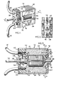
- the motor includes a generally U-shaped motor frame 12 made from steel.
- the motor frame is basically two planar legs 14 and 16 that are generally parallel and spaced from each other. The two legs are joined at one end by a generally planar central portion 18.
- the spaced legs and the central portion define a space within which is mounted a plastic spacer 20 and a pair of opposed permanent magnets 22 and 24 that surround a rotating armature 26.
- One end of the armature terminates in a shaft portion 28 which is received within a bushing 30 that is mounted at the center of the planar central portion 18.
- the other end of the armature terminates in a shaft portion 34.
- a commutator 36 Next to the armature and mounted on the shaft portion 34 is a commutator 36. Shaft portion 34 passes through a bushing 38 that is defined as part of a non-conductive insert 40 which mates with the distal ends of the legs 14 and 16 of the motor frame 12. Also mounted on the non-conductive member 40 are a pair of brush assemblies 42 and 44.
- the brush assemblies are identical and therefore only one will be described in detail. Taking brush assembly 42 as exemplary, the assembly basically consists of a pair of planar, opposed parallel legs 52 and 54. The legs are joined together by a planar portion 56. Near the center of' the planar portion 56 is a circular opening 58 that is made up of a number of symmetrically arranged, resilient fingers 60.
- One of the legs 52 contains an extension in the form of a brush leaf 62 within which is mounted a carbon brush 64.
- a wire W having a greater diameter D than the diameter defined between the fingers 60 is pushed into the opening 58 causing the fingers 60 to yield, allowing the wire to penetrate as shown in Figure 3. Because of their resiliency, the fingers prevent withdrawal of the wire W after it has been inserted into the opening 58. In this way a solderless connection is formed between the brush assembly and a wire W that is connected to a source of voltage for operating the motor.
- FIGS 1-3 show the details of a permanent magnet motor embodying the invention.
- the motor 10 contains a motor frame 12 consisting of a pair of flat, generally parallel and spaced legs 14 and 16 joined at one end by a generally planar portion 18.
- the metallic motor frame 12 essentially defines the overall size of the motor.
- the thin metallic motor frame matches with the radial thickness of the permanent magnets 22 and 24 to establish the optimum energy level in the air gap 27 between each magnet and the armature.
- the geometry of the motor frame allows the magnets 22 and 24 to be as wide as the width 41 of the frame thereby increasing the total area of magnetic flux and also elmininating the short circuiting of flux through the sidewalls.
- an aperture 31 is provided within which is mounted bushing 30.
- the planar central portion 18 contains an interior surface 74 that receives non-conductive insert 20 generally made of a non-conductive material such as plastic.
- the insert 20 has the overall shape of a thin rectangular solid and is defined by a central portion 82 and two side portions 84 and 86. The central portion is joined to each of the side portions through the intermediary of a connecting web 88 and 90.
- an aperture 92 which encircles the periphery of the bearing 30 when the insert is mounted next to the interior surface 74.
- the insert 20 contains two planar surfaces 96 and 98. Defined on surface 98 are a pair of projecting cylindrical bosses 102 and 104. These cylindrical bosses are spaced relative to the aperture 92 so that the cylindrical bosses mate with the apertures 70 and 72 defined on the motor frame 12.
- the other surface 96 of insert 20 contains upwardly projecting guide rails 105 and 107. As will be explained hereinafter, these guide rails are shaped and spaced to facilitate placement and alignment of the magnets 22 and 24 within the motor frame 12.
- insert 40 generally comprises a plastic block that has an interior hollow 122 which is shaped to be larger than the commutator 36 that resides within the hollow.
- the outermost portion of the insert 40 defines a generally planar rectangular member 124.
- a plastic bushing 38 that holds a metallic tubular bushing 39.
- a pair of indented grooves 132 and 134 Positioned on either side of each aperture 126 and 128 are a pair of indented grooves 132 and 134. These grooves each have a longitudinal axis that is generally parallel to the longitudinal axis of the apertures 126 and 128.
- the grooves 132 and 134 also define groove surfaces which are generally parallel to and spaced from each other.
- troughs 138 and 140 At each of the extreme ends of the rectangular member 124 is defined troughs 138 and 140. These troughs extend throughout the full width of the body 40 and define an open area for receiving legs 112 and 114.
- stepped inserts 142 and 144 Positioned about either side of the troughs 138 and 140 are stepped inserts 142 and 144 which mate with the corresponding steps 116 and 118 of the motor frame 12. Also defined at each end of the rectangular member 124 are a pair of slits 146 and 148. These slits receive the legs of one of the electrical contacts 42 and 44 in the manner to be described hereinafter.
- the motor frame 12 and the two plastic inserts 20 and 40 define a space within which is mounted the pair of opposed permanent magnets 22 and 24 and the rotating armature 26.
- Each of the magnets is a generally rectangular solid with the major flat surface 21 of the rectangular solid placed in mating relationship with the interior surface of one of the legs 14 and 16 of the motor frame 12.
- the opposite surface 23 of each of the magnets is curved to conform with the curved surface of the armature 26.
- the radius of the curved surface 23 defined in the magnet is greater than the radius of the armature 26 in order to create an air gap 27 between the magnet and the armature.
- the side surfaces 51 and 53 ( Figure 4) of each magnet are exposed and not covered by the sidewall supports found in prior art motors, thus eliminating the problem of short circuiting of flux through the sidewalls.
- insert 40 contains two edge projections 152 and 154 that contain edges 156 and 158 ( Figure 8) which together define boundaries for positioning the permanent magnets in the manner to be described hereinafter.
- each of the magnets 22 and 24 are mounted within the motor frame so that the major surface area of each magnet is pressed up against the interior surface of one of the legs 14 and 16.
- the extreme ends of each magnet are located by each of the inserts 20 and 40 in order to stabilize the magnet.
- the armature 26 which has one end 28 in bushing 30 and the other end passing through metallic bushing 39.
- the commutator 36 of the motor is positioned within hollow 122 of insert 40. Also positioned within this insert in the manner to be described hereinafter is the leaf assemblies or brush gear 42 and 44.
- brush gear 42 generally comprises a pair of horizontally extending legs 52 and 54 which are joined at their upper ends by transverse planar member 56.
- the planar legs are elongated and generally have a width that is less than the thickness of the planar surface.
- Each of the legs contains an inwardly projecting dimple 162 that rides in one of the grooves 132 and 134 when the brush gear is mounted on the insert 40.
- Each of the legs also contains an inwardly projecting triangular barb 164. Because the barb terminates in a sharp point 166, once the brush gear is mounted on the insert, it .is difficult to remove it because of the resistance provided by the point engaging the surface of either of the grooves 132 and 134.
- an elongated finger 168 emanates from one side of the leg.
- the finger terminates in a brush leaf 62 that contains an aperture 63 for receiving a carbon brush 64.
- the planar surface 56 of the brush gear contains aperture 58 near its central portion.
- the aperture is generally square with fingers 60 emanating inwardly toward each other from each of the corners of the square.
- the fingers occupy the same plane as the planar surface 56 and are directed inwardly towards the center of the square.
- the ends of the fingers define an opening 172 that is approximately 80% of the diameter of a wire W which is to be inserted within the opening.
- the brush gear structure is approximately .11 to .12 millimeter thick with a preferred range of .08 - .15 millimeters.
- the brush gear is made of beryllium cooper.
- Brush gear 44 is of precisely the same construction as brush gear 42. Each brush gear is positioned on the outer surface of insert 40 so that legs 52 and 54 are received within slits 146 and 148. Likewise, the dimples 162 and the barbs 164 are caused to ride within grooves 132 and 134 as the contact is brought into its final resting place against the surface 125 of insert 40.
- the holes 126 and 128 in insert 40 are arranged to coincide with the opening 58 so that when a wire W is inserted into the opening 58 the end of the wire is permitted to occupy up to the full length of the hole 128.
- the fingers 60 are caused to bend inwardly as shown in Figure 3. This inward bending prevents removal of the wire W under normal conditions of use. This construction thus provides the solderless connection.
- the brush leaf 62 and extension 168 are positioned within hollow 122 as defined by insert 40.
- the carbon brush 64 of brush leaf 62 is operatively associated with commutator 26.
- the size of the hollow 122 is made as large as possible in order to maximize the length of brush 64.
Landscapes
- Motor Or Generator Frames (AREA)
Applications Claiming Priority (4)
| Application Number | Priority Date | Filing Date | Title |
|---|---|---|---|
| GB08526254A GB2183106A (en) | 1985-10-24 | 1985-10-24 | A solderless terminal for an electric motor |
| GB8526254 | 1985-10-24 | ||
| US824549 | 1986-01-23 | ||
| US06/824,549 US4705972A (en) | 1985-10-24 | 1986-01-23 | Solderless electrical connection in a motor |
Publications (2)
| Publication Number | Publication Date |
|---|---|
| EP0220955A2 true EP0220955A2 (fr) | 1987-05-06 |
| EP0220955A3 EP0220955A3 (fr) | 1988-10-05 |
Family
ID=26289927
Family Applications (1)
| Application Number | Title | Priority Date | Filing Date |
|---|---|---|---|
| EP86308305A Withdrawn EP0220955A3 (fr) | 1985-10-24 | 1986-10-24 | Assemblage d'un dispositif porte-balais pour utilisation dans un moteur |
Country Status (2)
| Country | Link |
|---|---|
| EP (1) | EP0220955A3 (fr) |
| AU (1) | AU6410286A (fr) |
Cited By (2)
| Publication number | Priority date | Publication date | Assignee | Title |
|---|---|---|---|---|
| WO2012168131A1 (fr) * | 2011-06-08 | 2012-12-13 | Valeo Systèmes d'Essuyage | Assemblage support charbon |
| US9714009B2 (en) | 2011-06-17 | 2017-07-25 | Valeo Systèmes d'Essuyage | Connector support and windscreen washer liquid distribution device for motor vehicle windscreen wipers |
Family Cites Families (2)
| Publication number | Priority date | Publication date | Assignee | Title |
|---|---|---|---|---|
| US3433989A (en) * | 1966-08-10 | 1969-03-18 | Rowe Ind Inc | Brush retaining means for an electric motor |
| CH659918A5 (en) * | 1983-06-09 | 1987-02-27 | Landis & Gyr Ag | Clamping device |
-
1986
- 1986-10-16 AU AU64102/86A patent/AU6410286A/en not_active Abandoned
- 1986-10-24 EP EP86308305A patent/EP0220955A3/fr not_active Withdrawn
Cited By (5)
| Publication number | Priority date | Publication date | Assignee | Title |
|---|---|---|---|---|
| WO2012168131A1 (fr) * | 2011-06-08 | 2012-12-13 | Valeo Systèmes d'Essuyage | Assemblage support charbon |
| FR2976411A1 (fr) * | 2011-06-08 | 2012-12-14 | Valeo Systemes Dessuyage | Assemblage support charbon |
| CN103733444A (zh) * | 2011-06-08 | 2014-04-16 | 法雷奥系统公司 | 电刷保持器组件 |
| CN103733444B (zh) * | 2011-06-08 | 2017-05-24 | 法雷奥系统公司 | 电刷保持器组件 |
| US9714009B2 (en) | 2011-06-17 | 2017-07-25 | Valeo Systèmes d'Essuyage | Connector support and windscreen washer liquid distribution device for motor vehicle windscreen wipers |
Also Published As
| Publication number | Publication date |
|---|---|
| AU6410286A (en) | 1987-04-30 |
| EP0220955A3 (fr) | 1988-10-05 |
Similar Documents
| Publication | Publication Date | Title |
|---|---|---|
| US3967148A (en) | Brush holder assembly | |
| US5159222A (en) | Brush holder assembly having snap-in replaceable commutator brush holder cartridges for electric machines | |
| EP0706727B1 (fr) | Ensemble porte-balai | |
| KR100299429B1 (ko) | 신규한브러시홀더를가지는브러시홀더조립체 | |
| EP0863602B1 (fr) | Rotor pour moteur électrique | |
| US4071793A (en) | Field subassembly for electric motors | |
| CA1165368A (fr) | Appareil de chauffage electrique et isolateur d'appui pour element chauffant connexe | |
| EP0438412A1 (fr) | Bobinage de champ de moteur a prise intermediaire. | |
| CN109314446B (zh) | 接地端子、盖组件及包括其的电机 | |
| US4705972A (en) | Solderless electrical connection in a motor | |
| EP0282670B1 (fr) | Induit pour un moteur électrique | |
| CN1021679C (zh) | 一种电枢 | |
| JPS58170345A (ja) | 車両用3相発電機の製造方法 | |
| EP0790693A2 (fr) | Pince de rétention de balais et connexion électrique | |
| EP0271175B1 (fr) | Collecteur | |
| US4983872A (en) | Brush gear for a permanent magnet motor | |
| EP0220955A2 (fr) | Assemblage d'un dispositif porte-balais pour utilisation dans un moteur | |
| JPH0759301A (ja) | ブラシ保持板及びそれを備えた電動モーター | |
| JPH0717251Y2 (ja) | コレクタ装置 | |
| US4490004A (en) | Connector for connecting insulated wires to a circuit board | |
| EP0350193B1 (fr) | Un induit | |
| EP0570832A1 (fr) | Assemblage de boîtier de connecteur pour des fils discrets | |
| JP2870256B2 (ja) | 電気接触子の製造方法 | |
| JPS63228943A (ja) | 電機子巻線と整流子片とを接続する方法 | |
| KR970006107B1 (ko) | 전기자(Armature) 및 전기자 코일을 전기자 터미네이션에 연결하는 방법 |
Legal Events
| Date | Code | Title | Description |
|---|---|---|---|
| PUAI | Public reference made under article 153(3) epc to a published international application that has entered the european phase |
Free format text: ORIGINAL CODE: 0009012 |
|
| AK | Designated contracting states |
Kind code of ref document: A2 Designated state(s): DE GB IT |
|
| PUAL | Search report despatched |
Free format text: ORIGINAL CODE: 0009013 |
|
| AK | Designated contracting states |
Kind code of ref document: A3 Designated state(s): DE GB IT |
|
| STAA | Information on the status of an ep patent application or granted ep patent |
Free format text: STATUS: THE APPLICATION IS DEEMED TO BE WITHDRAWN |
|
| 18D | Application deemed to be withdrawn |
Effective date: 19890406 |
|
| RIN1 | Information on inventor provided before grant (corrected) |
Inventor name: BAINES, ROGER FREDERICK |