EP0220975A1 - Ausstellverpackung für ein Glas oder dergleichen - Google Patents
Ausstellverpackung für ein Glas oder dergleichen Download PDFInfo
- Publication number
- EP0220975A1 EP0220975A1 EP86402061A EP86402061A EP0220975A1 EP 0220975 A1 EP0220975 A1 EP 0220975A1 EP 86402061 A EP86402061 A EP 86402061A EP 86402061 A EP86402061 A EP 86402061A EP 0220975 A1 EP0220975 A1 EP 0220975A1
- Authority
- EP
- European Patent Office
- Prior art keywords
- flap
- flaps
- tray
- blank
- sides
- Prior art date
- Legal status (The legal status is an assumption and is not a legal conclusion. Google has not performed a legal analysis and makes no representation as to the accuracy of the status listed.)
- Granted
Links
- 239000011521 glass Substances 0.000 title claims abstract description 9
- 238000004806 packaging method and process Methods 0.000 title claims abstract description 7
- 239000000463 material Substances 0.000 claims abstract description 5
- 239000002994 raw material Substances 0.000 description 5
- 238000004026 adhesive bonding Methods 0.000 description 4
- 238000007493 shaping process Methods 0.000 description 4
- 238000004519 manufacturing process Methods 0.000 description 3
- 230000035622 drinking Effects 0.000 description 2
- 238000012986 modification Methods 0.000 description 1
- 230000004048 modification Effects 0.000 description 1
Images
Classifications
-
- B—PERFORMING OPERATIONS; TRANSPORTING
- B65—CONVEYING; PACKING; STORING; HANDLING THIN OR FILAMENTARY MATERIAL
- B65D—CONTAINERS FOR STORAGE OR TRANSPORT OF ARTICLES OR MATERIALS, e.g. BAGS, BARRELS, BOTTLES, BOXES, CANS, CARTONS, CRATES, DRUMS, JARS, TANKS, HOPPERS, FORWARDING CONTAINERS; ACCESSORIES, CLOSURES, OR FITTINGS THEREFOR; PACKAGING ELEMENTS; PACKAGES
- B65D5/00—Rigid or semi-rigid containers of polygonal cross-section, e.g. boxes, cartons or trays, formed by folding or erecting one or more blanks made of paper
- B65D5/42—Details of containers or of foldable or erectable container blanks
- B65D5/44—Integral, inserted or attached portions forming internal or external fittings
- B65D5/50—Internal supporting or protecting elements for contents
- B65D5/5021—Integral elements for containers formed by folding-up portions connected to a central panel from all sides
Definitions
- the present invention relates to a display packaging for glass and the like, produced from a blank of pliable material, which is cut and folded in the form of a tray, said blank comprising a rectangular panel forming a bottom wall of the tray , first and second flaps having roughly a rectangular shape, which are respectively adjoining the long sides of the rectangular panel and which form side walls of the tray, third and fourth flaps having a roughly rectangular shape, which are respectively adjoining short sides of the rectangular panel and which form end walls of the tray, a first pair of fixing lugs which are respectively adjacent to two opposite sides of one of the first and third flaps, a second pair of fixing lugs which are attached respectively to two opposite sides of one of the second and fourth flaps, the two pairs of fixing lugs serving to f ix the first and second flaps to the third and fourth flaps, a retaining tab which is cut in the third flap and which can be folded inwards from the tray to retain one end of an article contained therein, means retaining to retain another end of the article, said retaining
- the present invention therefore aims to provide a tray whose manufacture is simpler, shorter and less expensive, and which requires a quantity of raw material less than the known tray.
- the display package of the present invention is characterized in that said retaining means further comprise two tabs which are respectively adjacent to the short sides of the fifth flap which are perpendicular to said outer side of the fourth flap, and which are intended to be fixed respectively to the first and second flaps.
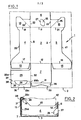
- the blank 1 shown in Figure 1, from which the known tray is formed, is cut from a sheet of cardboard, plasticized cardboard or other suitable material, which must have at least the dimensions of the rectangular frame 2 shown in phantom in Figure 1.
- the blank 1 comprises a rectangular panel 3, which is intended to form the bottom of the tray, two flaps 4 and 5 having roughly a rectangular shape, which are intended to form the side walls of the tray, and two rectangular flaps 6 and 7, which are intended to form end walls of the tray.
- the two flaps 4 and 5 adjoin respectively to the long sides 8 and 9 of the panel 3, while the two flaps 6 and 7 adjoin respectively to the two short sides 11 and 12 of the panel 3.
- the sides 8, 9, 11 and 12 of panel 3 form fold lines for flaps 4, 5, 6 and 7.
- the blank 1 further comprises four fixing lugs 13, 14, 15 and 16, which adjoin the sides 17, 18, 19 and 21 respectively of the flaps 4 and 5.
- the lugs 14 and 16 are also adjoining part of the sides 22 and 23, respectively, of the flap 6, and they are divided into two parts by fold lines 24 and 25, respectively, which extend outward from the ends of the side 11 of the panel 3 and which form a 45 ° angle with respect to the sides 18 and 21 of the flaps 4 and 5.
- the sides 17, 18, 19, 21, 22 and 23 of the flaps 4,5 and 6 also form fold lines for the fixing lugs 13 to 16.
- a retaining tab 26 is cut from the flap 6 and can be folded inwards from the tray around a fold line 27 which extends perpendicular to the short side 11 of the panel 3 in the middle of the flap 6.
- the blank 1 further comprises two other flaps 28 and 29 which are respectively adjacent to the side 31 and to a part of the side 32 of the flap 7, the sides 31 and 32 forming fold lines for the flaps 28 and 29.
- side outside 33 of the flap 28 is curved towards the fold line 31.
- an opening 34 having roughly the shape of a trapezoid whose small base 35 is adjacent to the side 36 of the flap 29 and curved towards the latter with a curvature corresponding to that of the side 33 of the flap 28.
- Two fold lines 37 and 38 are formed in the flap 29 parallel to the side 36 and substantially in correspondence with the large and small bases of the trapezoidal opening 34, respectively.
- the large outer sides 39 and 41 of the two flaps 4 and 5 are largely indented so as to make visible a substantial part of the sides of the article 42 contained in the tray.
- a first phase the flaps 4, 5 and 6 are folded at 90 ° around the fold lines 8, 9 and 11, respectively.
- the two fixing lugs 14 and 16 fold around the fold lines 18, 22, 24 and 21, 23, 25, respectively, by forming bellows which are fixed by gluing to the internal face of the flap 6 .
- the flap 28 is first folded around the fold line 31 so as to make a predetermined angle (approximately 70 °) with the flap 7. Then the flap 29 is folded 180 ° around the fold line 32, and its part 29a is glued to the internal face of the flap 7. Next, the part 29b of the flap 29 is folded up around the fold line 37 and the part 29c of the flap 29 is folded towards the bottom around the fold line 38 and glued to the outer face of the flap 28 as shown in Figure 2. At this time, the small curved base 35 of the trapezoidal opening 34 is coincident with the curved part of the edge 33 flap 28.
- the article 42 is deposited in the container partially formed during the first and second phases.
- the flap 7 is folded 90 ° around the fold line 12, and the fixing lugs 13 and 15 are folded 90 ° respectively around the fold lines 17 and 19 and glued against the outer face of the flap 7.
- the parts 29b and 29c of the flap 29 and the flap 28 form a flange which retains the base of the article 42 to prevent it from coming out of the tray, the base of the article 42 being partially engaged in the opening 34 of the flap 29.
- the retaining tab 26 is knocked inwardly of the tray so as to penetrate into the "drinking" of the glass or the cup 42, and it also contributes to preventing it from leaving the tray.
- the positioning of article 42 in the tray must be carried out before the flap 7 is folded down and the tabs 13 and 15 are fixed to the flap 7 (fourth phase). Otherwise, if the fourth phase was carried out before the third phase, the placing of the article 42 in the tray could not be carried out or could only be carried out with difficulty because of the presence of the rim formed by the parts 29b and 29c of the flap 29. Consequently, the known tray cannot be completely shaped in a single phase and using a single machine, but it must be shaped in several phases, as has been described. above, using several machines.
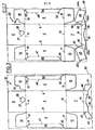
- the tray of the present invention can be obtained from the blank 10 shown in Figure 3.
- the blank 10 is cut from a sheet of semi-rigid and pliable material, such as cardboard, plasticized cardboard or plastic.
- the elements of the blank 10 which are identical or which play the same role as those of the blank 1 of FIG. 1 are designated by the same reference numbers and will therefore not be described again in detail.
- the blank 10 differs essentially from the blank 1 of FIG. 1 in that it does not have a flap 29, but two legs 43 and 44 which are attached respectively to the short sides 45 and 46 of the flap 28, which form fold lines for legs 43 and 44.
- each of the two flaps 4 and 5 has a fold line 47 or 48, respectively, which extends parallel to the long sides 8 and 9 of the panel 3 over a major part of the length of the flaps 4 and 5.
- Two incisions 49 and 51 are formed in the flap 4 and each extend from one of the ends of the line of folding 47 towards one of the ends of the large outer side of the flap 4.
- two other incisions 52 and 53 are formed in the flap 5 and each extend from one of the ends of the folding line 48 towards one of the ends of the large outer side of the flap 5.
- the fixing lugs 14 and 16 of the blank 10 shown in Figure 3 are only adjoining the sides 18 and 21 of the flaps 4 and 5, and the lug of the fixing 16 has a notch 54 which will be seen below.
- the tray of the present invention can be shaped and filled with an article in the following manner.
- the four flaps 4,5,6 and 7 are folded 90 ° around the fold lines 8, 9, 11 and 12, respectively.
- the four fixing lugs 13, 14, 15 and 16 are folded 90 ° around the fold lines 17, 18, 19 and 21, respectively, and are fixed to the flaps 6 and 7.
- the fixing lugs 13 and 15 can be placed against the external face or against the internal face of the flap 7 and the fixing lugs 14 and 16 can be placed against the external face or against the internal face of the flap 6, as desired.
- the fixing of the tabs 13, 14, 15 and 16 to the flaps 6 and 7 can be obtained by gluing or by stapling. All of these operations can be carried out in a single phase by means of a known machine known as a "tray lifter". At the end of this first phase, the tray is almost completely formed.
- the parts 4a and 5a of the flaps 4 and 5 are folded respectively around the fold lines 47 and 48 towards the inside of the tray in order to double and stiffen the side walls of the latter, while forming large notches in said side walls to make the article which will then be deposited in the tray even more visible.
- the operation of folding parts 4a and 5a can be carried out using very simple means, without increasing the duration of the tray shaping and filling cycle. Indeed, this operation can be performed during the transfer of the tray between the "tray" and a filling station, without stopping the movement of the tray.
- a second phase an article such as a goblet or a stemmed glass is placed in the tray.
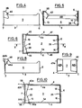
- the flap 28 is folded around the fold line 31 towards the inside of the tray so as to form a predetermined angle (approximately 70 °) with the flap 7 as shown in FIG. 5.
- the two legs 43 and 44 are folded 90 ° around the fold lines 45 and 46 and fixed respectively to the flaps 4 and 5.
- the legs 43 and 4 4 are fixed to the outer face of the flaps 4 and 5 as shown in the " Figures 4 to 6.
- the fixing of the legs 43 and 44 to the flaps 4 and 5 can be obtained for example by gluing or by stapling.
- the flap 28 forms a rim which prevents the base of the goblet or the stemmed glass contained in the tray from coming out of the latter.
- the retaining tab 26 is knocked inwards from the tray as shown in Figures 5 and 6, so to be engaged in the "drinking" of the cup or glass to prevent it from leaving the bar quette.
- the routing of the retaining tab 26 is enabled by the notch 54 which, once the fixing tab 16 has been fixed to the flap 6, is in coincidence with the retaining tab 26.
- the tray of the present invention obtained from the blank of Figure 10, requires for its shaping and filling a smaller number of phases than in the case of the tray obtained from the blank 1 of FIG. 1, since the tray itself can be shaped in a single phase, and this by using a conventional "tray maker".
- the operations for folding down the flap 28 and the two tabs 43 and 44 of the blank 10 are simpler to perform than the operations for folding down the flaps 28 and 29 and the operations for folding the parts 29b and 29c of the flap. 29 of the blank 1 of Figure 1, and therefore require less complicated tools.
- FIG. 7 shows another blank 30 from which the tray of the present invention can be obtained.
- the elements of the blank 30 which are identical or which play the same role as those of the blank 10 of FIG. 3 are designated by the same reference numbers and will not be described again in detail.
- the blank 30 differs from the blank 10 in that each of the two legs 43 and 44 comprises a part 43a or 44a in the form of an isosceles triangle, attached to a part 43b or 44b in the form of a trapezoid.
- the base of the isosceles triangle 43a is formed by the short side 45 of the flap 28, while the base of the isosceles triangle 44a is formed by the other short side 46 of the flap 28.
- the side 55 of the part 43a forms both a fold line and part of the large base of the trapezium-shaped part 43b.
- the side 56 of the part 44a forms both a fold line and part of the large base of the trapezoid-shaped part 44b.
- the tray obtained from the blank 30 of Figure 7 is shaped and filled in a manner similar to what has been described above with respect to the tray obtained from the blank 10 of Figure 3.
- the only difference resides in that, after having folded the flap 28 around the fold line 31 and after having folded the two legs 43 and 44 by 90 ° respectively around the fold lines 45 and 46 to apply the parts 43a and 44a against the face exterior of the flaps 4 and 5, respectively, the fold lines 55 and 56 are then coincident with the vertical edges of the tray located respectively at the angles formed between the flap 7 and each of the two flaps 4 and 5.
- the parts 43b and 44b are then folded 90 ° respectively around the fold lines 55 and 56 towards the external face of the flap 7 as shown in FIGS. 8 to 10, and they are fixed to this flap for example by gluing or stapling.
- the parts 43a and 44a may not be fixed to the flaps 4 and 5, although it is preferable to fix them there.
- the blank 30 of FIG. 7 is inscribed in a rectangular frame 40 whose length is shorter than that of the frame 20 in which the blank 10 is inscribed.
- the blank 30 allows therefore a saving of raw material greater than the blank 10.
- the fixing lugs 13, 14, 15 and 16 could be adjoining the short sides of the flaps 6 and 7.
- the four fixing lugs 13, 14, 15 and 16 could be formed by lugs similar to the lugs 14 and 16 of the blank 1 of FIG. 1.
Landscapes
- Engineering & Computer Science (AREA)
- Mechanical Engineering (AREA)
- Cartons (AREA)
- Glass Compositions (AREA)
Priority Applications (1)
| Application Number | Priority Date | Filing Date | Title |
|---|---|---|---|
| AT86402061T ATE41904T1 (de) | 1985-09-20 | 1986-09-19 | Ausstellverpackung fuer ein glas oder dergleichen. |
Applications Claiming Priority (2)
| Application Number | Priority Date | Filing Date | Title |
|---|---|---|---|
| FR8513965A FR2587686B1 (fr) | 1985-09-20 | 1985-09-20 | Emballage-presentoir pour verre et article similaire |
| FR8513965 | 1985-09-20 |
Publications (2)
| Publication Number | Publication Date |
|---|---|
| EP0220975A1 true EP0220975A1 (de) | 1987-05-06 |
| EP0220975B1 EP0220975B1 (de) | 1989-04-05 |
Family
ID=9323100
Family Applications (1)
| Application Number | Title | Priority Date | Filing Date |
|---|---|---|---|
| EP86402061A Expired EP0220975B1 (de) | 1985-09-20 | 1986-09-19 | Ausstellverpackung für ein Glas oder dergleichen |
Country Status (5)
| Country | Link |
|---|---|
| EP (1) | EP0220975B1 (de) |
| JP (1) | JPS62122941A (de) |
| AT (1) | ATE41904T1 (de) |
| DE (1) | DE3662672D1 (de) |
| FR (1) | FR2587686B1 (de) |
Cited By (2)
| Publication number | Priority date | Publication date | Assignee | Title |
|---|---|---|---|---|
| EP0213262A3 (de) * | 1985-08-29 | 1988-04-20 | Anchor Hocking Corporation | Schaupackungsmodul |
| US5886137A (en) * | 1994-08-27 | 1999-03-23 | Basf Aktiengesellschaft | Preparation of salts of polyaspartic acid and their use in detergents and cleaners |
Families Citing this family (1)
| Publication number | Priority date | Publication date | Assignee | Title |
|---|---|---|---|---|
| JP5244193B2 (ja) * | 2007-11-15 | 2013-07-24 | グラフィック パッケージング インターナショナル インコーポレイテッド | 容器用パッケージ |
Citations (3)
| Publication number | Priority date | Publication date | Assignee | Title |
|---|---|---|---|---|
| GB915434A (en) * | 1960-06-29 | 1963-01-09 | William Teacher And Sons Ltd | Improvements in and relating to collapsible cartons or containers |
| FR1496684A (fr) * | 1966-10-14 | 1967-09-29 | Sprinter Pack Ab | Boîte ou casier d'emballage en carton |
| US3397772A (en) * | 1967-02-09 | 1968-08-20 | Reynolds Metals Co | Display carton for a bottle-like container and blanks for making same |
Family Cites Families (1)
| Publication number | Priority date | Publication date | Assignee | Title |
|---|---|---|---|---|
| FR915434A (fr) * | 1945-05-23 | 1946-11-06 | Csf | Chauffage des matériaux diélectriques par champs électriques à haute fréquence |
-
1985
- 1985-09-20 FR FR8513965A patent/FR2587686B1/fr not_active Expired
-
1986
- 1986-09-19 DE DE8686402061T patent/DE3662672D1/de not_active Expired
- 1986-09-19 EP EP86402061A patent/EP0220975B1/de not_active Expired
- 1986-09-19 AT AT86402061T patent/ATE41904T1/de not_active IP Right Cessation
- 1986-09-20 JP JP61223477A patent/JPS62122941A/ja active Pending
Patent Citations (3)
| Publication number | Priority date | Publication date | Assignee | Title |
|---|---|---|---|---|
| GB915434A (en) * | 1960-06-29 | 1963-01-09 | William Teacher And Sons Ltd | Improvements in and relating to collapsible cartons or containers |
| FR1496684A (fr) * | 1966-10-14 | 1967-09-29 | Sprinter Pack Ab | Boîte ou casier d'emballage en carton |
| US3397772A (en) * | 1967-02-09 | 1968-08-20 | Reynolds Metals Co | Display carton for a bottle-like container and blanks for making same |
Cited By (2)
| Publication number | Priority date | Publication date | Assignee | Title |
|---|---|---|---|---|
| EP0213262A3 (de) * | 1985-08-29 | 1988-04-20 | Anchor Hocking Corporation | Schaupackungsmodul |
| US5886137A (en) * | 1994-08-27 | 1999-03-23 | Basf Aktiengesellschaft | Preparation of salts of polyaspartic acid and their use in detergents and cleaners |
Also Published As
| Publication number | Publication date |
|---|---|
| FR2587686A1 (fr) | 1987-03-27 |
| DE3662672D1 (en) | 1989-05-11 |
| JPS62122941A (ja) | 1987-06-04 |
| EP0220975B1 (de) | 1989-04-05 |
| ATE41904T1 (de) | 1989-04-15 |
| FR2587686B1 (fr) | 1988-02-12 |
Similar Documents
| Publication | Publication Date | Title |
|---|---|---|
| EP1562830B1 (de) | Schutzverpackung für polsterobjekt mit kreisförmiger kontur | |
| EP1135298B1 (de) | Flaschenverpackung | |
| WO1997010137A2 (fr) | Contenant livre a plat, puis mis en volume en deux phases distinctes, et portant de l'adhesif a effet prolonge | |
| EP0160602A1 (de) | Schaupackung für Gläser oder dergleichen | |
| FR2707260A1 (fr) | Emballage fermé pour un groupe ordonné d'objets tels que des contenants de boissons. | |
| EP0461947A1 (de) | Verpackungsvorrichtung für Gruppe von Objekten | |
| EP0220975B1 (de) | Ausstellverpackung für ein Glas oder dergleichen | |
| EP0919481A1 (de) | Verpackungsschachtel mit Festsetzungsanordnung | |
| EP0785138B1 (de) | Zuschnitte für Schachtel in der Form einer Schauverpackung und aus ihnen hergestellte Schachtel | |
| EP0114772B1 (de) | Zuschnitt für eine mit einem Handgriff versehene Verpackung und übereinstimmender Verpackungsentwurf und Verpackung | |
| EP0238384B1 (de) | Schauverpackung für mehrere in Reihe gestellte Trinkgläser oder gleiche Artikel | |
| EP0665167B1 (de) | Schachtel mit Aussenwänden und Innenträgerkörper | |
| EP0223623B1 (de) | Sich kreuzende Bänder, um in einem Behälter Abteilungen herzustellen | |
| CH446177A (fr) | Casier multicellulaire | |
| FR2489788A1 (fr) | Support pour recipients | |
| EP0277859B1 (de) | Schaupackung für Gläser und ähnliche Artikel | |
| FR2559128A1 (fr) | Perfectionnement aux sacs en matiere plastique | |
| FR2628392A1 (fr) | Emballage de presentation pour quatre articles disposes en carre | |
| WO1999059880A1 (fr) | Emballage a compartiments multiples | |
| FR2866630A1 (fr) | Emballage du genre boite en carton ou matiere similaire | |
| FR2605595A1 (fr) | Emballage en carton de conditionnement et de presentation d'un objet tel qu'un produit alimentaire ou un article fragile | |
| FR2550515A1 (fr) | Emballage en carton ou analogue | |
| CA1269078A (fr) | Emballage unitaire pour verre et article similaire | |
| FR2741860A1 (fr) | Flan en carton comportant des moyens permettant son maintien temporaire en volume lors de l'elaboration d'un paquet | |
| FR2718716A1 (fr) | Nouveau conditionnement pour bouteilles, en un matériau semi-rigide tel que le carton ondulé. |
Legal Events
| Date | Code | Title | Description |
|---|---|---|---|
| PUAI | Public reference made under article 153(3) epc to a published international application that has entered the european phase |
Free format text: ORIGINAL CODE: 0009012 |
|
| AK | Designated contracting states |
Kind code of ref document: A1 Designated state(s): AT BE CH DE GB IT LI LU NL SE |
|
| 17P | Request for examination filed |
Effective date: 19870306 |
|
| 17Q | First examination report despatched |
Effective date: 19880912 |
|
| GRAA | (expected) grant |
Free format text: ORIGINAL CODE: 0009210 |
|
| AK | Designated contracting states |
Kind code of ref document: B1 Designated state(s): AT BE CH DE GB IT LI LU NL SE |
|
| PG25 | Lapsed in a contracting state [announced via postgrant information from national office to epo] |
Ref country code: GB Effective date: 19890405 Ref country code: SE Effective date: 19890405 Ref country code: NL Effective date: 19890405 Ref country code: AT Effective date: 19890405 Ref country code: IT Free format text: LAPSE BECAUSE OF FAILURE TO SUBMIT A TRANSLATION OF THE DESCRIPTION OR TO PAY THE FEE WITHIN THE PRE;WARNING: LAPSES OF ITALIAN PATENTS WITH EFFECTIVE DATE BEFORE 2007 MAY HAVE OCCURRED AT ANY TIME BEFORE 2007. THE CORRECT EFFECTIVE DATE MAY BE DIFFERENT FROM THE ONE RECORDED.SCRIBED TIME-LIMIT Effective date: 19890405 |
|
| REF | Corresponds to: |
Ref document number: 41904 Country of ref document: AT Date of ref document: 19890415 Kind code of ref document: T |
|
| REF | Corresponds to: |
Ref document number: 3662672 Country of ref document: DE Date of ref document: 19890511 |
|
| NLV1 | Nl: lapsed or annulled due to failure to fulfill the requirements of art. 29p and 29m of the patents act | ||
| PG25 | Lapsed in a contracting state [announced via postgrant information from national office to epo] |
Ref country code: LU Free format text: LAPSE BECAUSE OF NON-PAYMENT OF DUE FEES Effective date: 19890930 Ref country code: CH Effective date: 19890930 Ref country code: BE Effective date: 19890930 Ref country code: LI Effective date: 19890930 |
|
| GBV | Gb: ep patent (uk) treated as always having been void in accordance with gb section 77(7)/1977 [no translation filed] | ||
| PLBE | No opposition filed within time limit |
Free format text: ORIGINAL CODE: 0009261 |
|
| STAA | Information on the status of an ep patent application or granted ep patent |
Free format text: STATUS: NO OPPOSITION FILED WITHIN TIME LIMIT |
|
| 26N | No opposition filed | ||
| BERE | Be: lapsed |
Owner name: VERRERIE CRISTALLERIE D'ARQUES J.G. DURAND & CIE Effective date: 19890930 |
|
| REG | Reference to a national code |
Ref country code: CH Ref legal event code: PL |
|
| PG25 | Lapsed in a contracting state [announced via postgrant information from national office to epo] |
Ref country code: DE Effective date: 19900601 |