EP0220992A1 - Vorrichtung zum Trennen von konischen Verbindungen in der Glasindustrie - Google Patents
Vorrichtung zum Trennen von konischen Verbindungen in der Glasindustrie Download PDFInfo
- Publication number
- EP0220992A1 EP0220992A1 EP86402386A EP86402386A EP0220992A1 EP 0220992 A1 EP0220992 A1 EP 0220992A1 EP 86402386 A EP86402386 A EP 86402386A EP 86402386 A EP86402386 A EP 86402386A EP 0220992 A1 EP0220992 A1 EP 0220992A1
- Authority
- EP
- European Patent Office
- Prior art keywords
- ring
- crown
- male
- conical
- endpiece
- Prior art date
- Legal status (The legal status is an assumption and is not a legal conclusion. Google has not performed a legal analysis and makes no representation as to the accuracy of the status listed.)
- Granted
Links
Images
Classifications
-
- B—PERFORMING OPERATIONS; TRANSPORTING
- B01—PHYSICAL OR CHEMICAL PROCESSES OR APPARATUS IN GENERAL
- B01L—CHEMICAL OR PHYSICAL LABORATORY APPARATUS FOR GENERAL USE
- B01L3/00—Containers or dishes for laboratory use, e.g. laboratory glassware; Droppers
- B01L3/56—Labware specially adapted for transferring fluids
- B01L3/565—Seals
-
- B—PERFORMING OPERATIONS; TRANSPORTING
- B25—HAND TOOLS; PORTABLE POWER-DRIVEN TOOLS; MANIPULATORS
- B25B—TOOLS OR BENCH DEVICES NOT OTHERWISE PROVIDED FOR, FOR FASTENING, CONNECTING, DISENGAGING, OR HOLDING
- B25B27/00—Hand tools, specially adapted for fitting together or separating parts or objects whether or not involving some deformation, not otherwise provided for
- B25B27/02—Hand tools, specially adapted for fitting together or separating parts or objects whether or not involving some deformation, not otherwise provided for for connecting objects by press fit or detaching same
- B25B27/10—Hand tools, specially adapted for fitting together or separating parts or objects whether or not involving some deformation, not otherwise provided for for connecting objects by press fit or detaching same inserting fittings into hoses
-
- F—MECHANICAL ENGINEERING; LIGHTING; HEATING; WEAPONS; BLASTING
- F16—ENGINEERING ELEMENTS AND UNITS; GENERAL MEASURES FOR PRODUCING AND MAINTAINING EFFECTIVE FUNCTIONING OF MACHINES OR INSTALLATIONS; THERMAL INSULATION IN GENERAL
- F16B—DEVICES FOR FASTENING OR SECURING CONSTRUCTIONAL ELEMENTS OR MACHINE PARTS TOGETHER, e.g. NAILS, BOLTS, CIRCLIPS, CLAMPS, CLIPS OR WEDGES; JOINTS OR JOINTING
- F16B7/00—Connections of rods or tubes, e.g. of non-circular section, mutually, including resilient connections
- F16B7/02—Connections of rods or tubes, e.g. of non-circular section, mutually, including resilient connections with conical parts
-
- F—MECHANICAL ENGINEERING; LIGHTING; HEATING; WEAPONS; BLASTING
- F16—ENGINEERING ELEMENTS AND UNITS; GENERAL MEASURES FOR PRODUCING AND MAINTAINING EFFECTIVE FUNCTIONING OF MACHINES OR INSTALLATIONS; THERMAL INSULATION IN GENERAL
- F16L—PIPES; JOINTS OR FITTINGS FOR PIPES; SUPPORTS FOR PIPES, CABLES OR PROTECTIVE TUBING; MEANS FOR THERMAL INSULATION IN GENERAL
- F16L49/00—Connecting arrangements, e.g. joints, specially adapted for pipes of brittle material, e.g. glass, earthenware
- F16L49/06—Joints in which sealing surfaces are pressed together by means of a member, e.g. swivel nut, screwed on, or into, one of the joint parts
Definitions
- the present invention relates to a device for disassembling conical joints in glassware, assembled by a screwed assembly ring.
- the invention relates to a device similar to that which is described and claimed in patent application FR 84 08 681 of June 1, 1984 in the name of the present applicant.
- disassembly assistance disk constitutes an annex piece which can be lost or lost, which constitutes a drawback when it is needed.
- the metal inevitably has sharp edges which sometimes cause glass breaks and injuries to the operator, not to mention the inconvenience of having to replace the seal in whole or in part.
- the present invention provides a device for disassembling the conical joints in glassware, composed of male and female conical end pieces, assembled by a screwed assembly ring, characterized in that it comprises a removable annular crown in plastic material, formed of a cylindrical part engaged between the assembly ring and the male end piece and of a flat part applied against the assembly ring between the latter and a circular projection formed on the male end piece.
- the invention allows both an economical device, supplied from the outset with each seal, which does not risk breaking the glass elements and which is however removable since it suffices to release the removable annular part from the '' male end piece to be able to slide the assembly ring along the male end piece beyond the circular projection and access the O-ring seal.
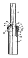
- the seal shown in the figure and designated by the general reference 10 consists of a first glass tip 12 of generally tubular shape, ending in a male conical end 14 defining with respect to the body of the tip a rear shoulder 16, and of a second end piece 18 of glass also of generally tubular shape and ending in a female conical end 20 ending in a front face 22 which, in assembled condition shown in the figure, is located substantially at same level as the posterior shoulder 16 of the male end piece.
- the seal comprises an assembly ring 24, of plastic material of cylindrical shape provided with an internal thread which cooperates with an external thread defined on the external surface of the female end-piece.
- the ring has a radial flange 30, on the side of the male end piece which constitutes a clamping flange for an O-ring 32 applied overlapping both on the rear shoulder 16 of the male end piece and the front face 22 of the 'female end piece, to ensure both positive locking of the two end pieces in assembled condition and additional sealing if the cooperation of the two tapered conical ends is not enough.
- the two end pieces are fixed at their other end to elements of a complete installation, for example laboratory apparatus also made of glass (not shown).
- the invention provides the following device:
- the male end piece is provided with a circular projection 34, integrally formed with the body of the end piece.
- a removable plastic crown 36 is assembled on the assembly ring 24 as follows:
- the crown consists of a generally cylindrical part 38 which is engaged in the space separating the tubular body from the male end piece. and the internal periphery of the assembly ring and of a flat annular part 40 which is applied to the upper face of the collar, therefore between the latter and the projection 34.
- the crown 36 is made removable thanks to a slot 42, which makes it possible to "open” it completely to disengage it from the male end piece, or only partially to allow it to pass optionally upwards over the projection 34 or towards the bottom over the posterior shoulder and the male tapered end 14.
- the ring 24 is unscrewed practically without effort until the crown 36 comes into contact with the projection 34.
- the natural flexibility of the plastic material constituting the crown 36 makes it possible to distribute the force uniformly over the entire periphery of the projection 34, and to avoid the mentioned drawbacks of the prior device in which this force is transmitted by sharp edges of a part. metallic.
- the invention provides to give this cylindrical part a sufficient length so that when the ring is lowered to its clamping position, the crown abuts against the O-ring and its flat part separates from the collar of the ring. . It is then easy to slide a fingernail or any other blade-shaped tool to release them completely.
Landscapes
- Engineering & Computer Science (AREA)
- General Engineering & Computer Science (AREA)
- Mechanical Engineering (AREA)
- Health & Medical Sciences (AREA)
- Clinical Laboratory Science (AREA)
- Chemical & Material Sciences (AREA)
- Chemical Kinetics & Catalysis (AREA)
- Closures For Containers (AREA)
Applications Claiming Priority (2)
| Application Number | Priority Date | Filing Date | Title |
|---|---|---|---|
| FR8515897A FR2589221B1 (fr) | 1985-10-25 | 1985-10-25 | Dispositif pour desassembler les joints coniques en verrerie |
| FR8515897 | 1985-10-25 |
Publications (2)
| Publication Number | Publication Date |
|---|---|
| EP0220992A1 true EP0220992A1 (de) | 1987-05-06 |
| EP0220992B1 EP0220992B1 (de) | 1990-05-09 |
Family
ID=9324213
Family Applications (1)
| Application Number | Title | Priority Date | Filing Date |
|---|---|---|---|
| EP19860402386 Expired - Lifetime EP0220992B1 (de) | 1985-10-25 | 1986-10-24 | Vorrichtung zum Trennen von konischen Verbindungen in der Glasindustrie |
Country Status (3)
| Country | Link |
|---|---|
| EP (1) | EP0220992B1 (de) |
| DE (1) | DE3671094D1 (de) |
| FR (1) | FR2589221B1 (de) |
Cited By (1)
| Publication number | Priority date | Publication date | Assignee | Title |
|---|---|---|---|---|
| US20170328385A1 (en) * | 2016-05-10 | 2017-11-16 | Bauer Deep Drilling Gmbh | Arrangement and method for connecting a hydraulic cylinder |
Families Citing this family (2)
| Publication number | Priority date | Publication date | Assignee | Title |
|---|---|---|---|---|
| DE3832437A1 (de) * | 1987-10-22 | 1989-05-03 | Buechi Lab Tech | Vorrichtung zum zusammenhalten und loesen konischer verbindungen |
| DE8714124U1 (de) * | 1987-10-22 | 1987-12-03 | BÜCHI LABORATORIUMS-TECHNIK AG, Flawil | Vorrichtung zum Zusammenhalten und Lösen konischer Verbindungen |
Citations (4)
| Publication number | Priority date | Publication date | Assignee | Title |
|---|---|---|---|---|
| DE467954C (de) * | 1928-11-03 | Siemens Schuckertwerke Akt Ges | Stangenverbindung | |
| GB1341702A (en) * | 1971-04-19 | 1973-12-25 | Jabling Co Ltd James A | Pipe connections |
| EP0069180A1 (de) * | 1981-07-06 | 1983-01-12 | Robert Joseph Miskinis | Propfen für Laborgeräte aus Glas |
| EP0147924A1 (de) * | 1983-10-31 | 1985-07-10 | Robert Joseph Miskinis | Vorrichtung zum Festsetzen von miteinander verbundenen Elementen für Laboreinrichtungen |
-
1985
- 1985-10-25 FR FR8515897A patent/FR2589221B1/fr not_active Expired
-
1986
- 1986-10-24 DE DE8686402386T patent/DE3671094D1/de not_active Expired - Fee Related
- 1986-10-24 EP EP19860402386 patent/EP0220992B1/de not_active Expired - Lifetime
Patent Citations (4)
| Publication number | Priority date | Publication date | Assignee | Title |
|---|---|---|---|---|
| DE467954C (de) * | 1928-11-03 | Siemens Schuckertwerke Akt Ges | Stangenverbindung | |
| GB1341702A (en) * | 1971-04-19 | 1973-12-25 | Jabling Co Ltd James A | Pipe connections |
| EP0069180A1 (de) * | 1981-07-06 | 1983-01-12 | Robert Joseph Miskinis | Propfen für Laborgeräte aus Glas |
| EP0147924A1 (de) * | 1983-10-31 | 1985-07-10 | Robert Joseph Miskinis | Vorrichtung zum Festsetzen von miteinander verbundenen Elementen für Laboreinrichtungen |
Cited By (2)
| Publication number | Priority date | Publication date | Assignee | Title |
|---|---|---|---|---|
| US20170328385A1 (en) * | 2016-05-10 | 2017-11-16 | Bauer Deep Drilling Gmbh | Arrangement and method for connecting a hydraulic cylinder |
| US10794406B2 (en) * | 2016-05-10 | 2020-10-06 | Bauer Deep Drilling Gmbh | Arrangement and method for connecting a hydraulic cylinder |
Also Published As
| Publication number | Publication date |
|---|---|
| EP0220992B1 (de) | 1990-05-09 |
| DE3671094D1 (de) | 1990-06-13 |
| FR2589221A1 (fr) | 1987-04-30 |
| FR2589221B1 (fr) | 1988-01-15 |
Similar Documents
| Publication | Publication Date | Title |
|---|---|---|
| EP0139712B1 (de) | Verfahren zum verbinden mehrerer teile, insbesondere teilen von rohrverbindungsstücken | |
| EP0511891B1 (de) | Verbindungselement zur Schnellkupplung eines Rohres | |
| FR2558563A1 (fr) | Accouplement emboitable pour relier l'extremite d'un tube a un tuyau flexible ou element analogue | |
| EP0261037A2 (de) | Garantieverschlussvorrichtung für einen mit einer Schraubgewindemündung versehenen Behälter | |
| FR2936782A1 (fr) | Dispositif de bouchage d'un col de recipient, recipient equipe d'un tel dispositif, et procede de bouchage d'un tel recipient | |
| EP2162663B1 (de) | Steckverbinder mit verbesserter aussenreinigung | |
| FR2800357A1 (fr) | Verseur ameliore et capsule a verseur incorpore | |
| FR2484050A1 (fr) | Dispositif de raccord pour tuyaux | |
| EP1089411B1 (de) | Vorrichtung bestimmt zur abgedichten Durchbohrung mit einem zylindrischen Objekt, Dose für ein elektrisches Gerät und Verfahren dafür | |
| FR2533278A1 (fr) | Butee de debrayage, notamment pour vehicule automobile | |
| EP0220992B1 (de) | Vorrichtung zum Trennen von konischen Verbindungen in der Glasindustrie | |
| WO2004035225A1 (fr) | Dispositif de fixation et distributeur comprenant un tel dispositif de fixation | |
| EP3895580A1 (de) | Mechanismus für einen behälter zum auftragen eines kosmetikprodukts und behälter, der einen solchen mechanismus umfasst und verfahren zur herstellung eines solchen mechanismus | |
| FR2721682A1 (fr) | Procédé pour réaliser une liaison entre une pièce tubulaire rigide et l'extrémité d'un tube thermoplastique. | |
| EP3895579B1 (de) | Mechanismus für einen behälter zum auftragen eines kosmetikprodukts und behälter, der einen solchen mechanismus umfasst | |
| FR2900129A1 (fr) | Dispositif de bouchage d'un recipient, recipient equipe d'un tel dispositif et procede de fabrication d'un tel dispositif | |
| FR2835811A1 (fr) | Insert fonctionnel pour goulot de recipient, typiquement une bouteille, et capsule de bouchage comprenant ledit insert | |
| EP2104634B1 (de) | Kappe für den hals eines behälters und verfahren zur herstellung einer solchen kappe | |
| EP2402640A1 (de) | Verschließbare Anschlussvorrichtung für den Transfer eines Fluids, und ihr Verschlussverfahren | |
| EP0958204A1 (de) | Metallbehälter für zu vernichtenden gegenstände | |
| FR2644223A1 (fr) | Raccord rapide et procede de montage | |
| CA1163657A (fr) | Element de tuyauterie constitutif d'un joint, procede et dispositif de fabrication de cet element | |
| EP0783085B1 (de) | In einer Bohrung einsetzbarer flexibler Teil | |
| FR2729206A1 (fr) | Procede pour realiser une liaison entre une piece tubulaire rigide et l'extremite d'un tube souple | |
| FR2680223A1 (fr) | Dispositif d'obturation d'un orifice forme dans la paroi d'une canalisation et ensemble constitue par un tel dispositif et la canalisation. |
Legal Events
| Date | Code | Title | Description |
|---|---|---|---|
| PUAI | Public reference made under article 153(3) epc to a published international application that has entered the european phase |
Free format text: ORIGINAL CODE: 0009012 |
|
| AK | Designated contracting states |
Kind code of ref document: A1 Designated state(s): DE GB IT |
|
| 17P | Request for examination filed |
Effective date: 19871029 |
|
| 17Q | First examination report despatched |
Effective date: 19881223 |
|
| GRAA | (expected) grant |
Free format text: ORIGINAL CODE: 0009210 |
|
| AK | Designated contracting states |
Kind code of ref document: B1 Designated state(s): DE GB IT |
|
| REF | Corresponds to: |
Ref document number: 3671094 Country of ref document: DE Date of ref document: 19900613 |
|
| GBT | Gb: translation of ep patent filed (gb section 77(6)(a)/1977) | ||
| ITF | It: translation for a ep patent filed | ||
| PLBE | No opposition filed within time limit |
Free format text: ORIGINAL CODE: 0009261 |
|
| STAA | Information on the status of an ep patent application or granted ep patent |
Free format text: STATUS: NO OPPOSITION FILED WITHIN TIME LIMIT |
|
| 26N | No opposition filed | ||
| ITTA | It: last paid annual fee | ||
| PGFP | Annual fee paid to national office [announced via postgrant information from national office to epo] |
Ref country code: GB Payment date: 19961018 Year of fee payment: 11 |
|
| PGFP | Annual fee paid to national office [announced via postgrant information from national office to epo] |
Ref country code: DE Payment date: 19961122 Year of fee payment: 11 |
|
| PG25 | Lapsed in a contracting state [announced via postgrant information from national office to epo] |
Ref country code: GB Free format text: LAPSE BECAUSE OF NON-PAYMENT OF DUE FEES Effective date: 19971024 |
|
| GBPC | Gb: european patent ceased through non-payment of renewal fee |
Effective date: 19971024 |
|
| PG25 | Lapsed in a contracting state [announced via postgrant information from national office to epo] |
Ref country code: DE Free format text: LAPSE BECAUSE OF NON-PAYMENT OF DUE FEES Effective date: 19980701 |
|
| PG25 | Lapsed in a contracting state [announced via postgrant information from national office to epo] |
Ref country code: IT Free format text: LAPSE BECAUSE OF NON-PAYMENT OF DUE FEES;WARNING: LAPSES OF ITALIAN PATENTS WITH EFFECTIVE DATE BEFORE 2007 MAY HAVE OCCURRED AT ANY TIME BEFORE 2007. THE CORRECT EFFECTIVE DATE MAY BE DIFFERENT FROM THE ONE RECORDED. Effective date: 20051024 |