EP0221048A2 - Elément de réglage pour une colonne - Google Patents
Elément de réglage pour une colonne Download PDFInfo
- Publication number
- EP0221048A2 EP0221048A2 EP86890292A EP86890292A EP0221048A2 EP 0221048 A2 EP0221048 A2 EP 0221048A2 EP 86890292 A EP86890292 A EP 86890292A EP 86890292 A EP86890292 A EP 86890292A EP 0221048 A2 EP0221048 A2 EP 0221048A2
- Authority
- EP
- European Patent Office
- Prior art keywords
- valve
- valves
- legs
- horizontal
- leg
- Prior art date
- Legal status (The legal status is an assumption and is not a legal conclusion. Google has not performed a legal analysis and makes no representation as to the accuracy of the status listed.)
- Withdrawn
Links
- 239000007789 gas Substances 0.000 claims abstract description 18
- 239000007788 liquid Substances 0.000 claims abstract description 5
- 229910000639 Spring steel Inorganic materials 0.000 claims description 2
- 238000010521 absorption reaction Methods 0.000 claims description 2
- 238000004821 distillation Methods 0.000 claims description 2
- 239000013013 elastic material Substances 0.000 claims description 2
- 238000000605 extraction Methods 0.000 claims description 2
- 238000000746 purification Methods 0.000 claims 1
- 239000012071 phase Substances 0.000 description 9
- 238000005452 bending Methods 0.000 description 3
- 230000000630 rising effect Effects 0.000 description 3
- 239000007792 gaseous phase Substances 0.000 description 2
- 238000004873 anchoring Methods 0.000 description 1
- 230000001174 ascending effect Effects 0.000 description 1
- 230000015572 biosynthetic process Effects 0.000 description 1
- 238000001311 chemical methods and process Methods 0.000 description 1
- 238000006243 chemical reaction Methods 0.000 description 1
- 238000004140 cleaning Methods 0.000 description 1
- 238000010276 construction Methods 0.000 description 1
- 238000011109 contamination Methods 0.000 description 1
- 230000007547 defect Effects 0.000 description 1
- 230000000694 effects Effects 0.000 description 1
- 230000007246 mechanism Effects 0.000 description 1
- 238000002156 mixing Methods 0.000 description 1
Images

Classifications
-
- B—PERFORMING OPERATIONS; TRANSPORTING
- B01—PHYSICAL OR CHEMICAL PROCESSES OR APPARATUS IN GENERAL
- B01D—SEPARATION
- B01D3/00—Distillation or related exchange processes in which liquids are contacted with gaseous media, e.g. stripping
- B01D3/14—Fractional distillation or use of a fractionation or rectification column
- B01D3/16—Fractionating columns in which vapour bubbles through liquid
- B01D3/163—Plates with valves
Definitions
- the invention relates to a valve base for mass transfer tanks for gas and steam flows to achieve intensive phase contact between liquids and gases or vapors for gas cleaning, distillation, absorption, extraction or the like with pivotable valves which have two legs arranged at an angle to one another.
- phase contact devices in a wide variety of designs are used in order to allow liquids and gases to come into direct contact and thereby react the various components.
- the upward flowing gases open the valves against the downward flow of liquid, whereby depending on the design this valve has to overcome a characteristic pressure difference.
- the pressure drop occurring when the valve flows through the valve should be kept as low as possible and the phase contact should be as intensive as possible.
- the construction should be simple to increase operational safety.
- such control elements are also known which are lined up next to one another as tilting elements which can be pivoted about a support element. In the rest position, their free ends rest on the tilting elements mounted on the neighboring support element. Under the influence of the ascending phase, all of the tilting elements around the longitudinal axis of the support element are up to a stop lying in the middle and above two adjacent support elements Rest position swiveling.
- the Ki pp eLemente are lined up in such a way that only a positive or a negative angle rotation can be carried out alternately from the adjacent tilting elements. With their weight, such tilting elements act entirely against the rising phase flow, which leads to a significant loss of pressure. In addition, there is also frictional resistance when twisting the tilting elements in order to overcome their ore axes, which naturally increases with increasing contamination.
- control elements it is also known - according to HU-PS 163 343 - to arrange such control elements in such a way that in the rest position they lie in the plane of the floor surface and thereby cover a corresponding opening.
- the single-sided, alternately on the opposite side, the control element connected to the floor surface is lifted off the floor surface by the rising flow pressure in the area of the free end and thus releases the floor opening.
- the entire weight of the control elements acts against the rising flow pressure.
- the call set of the present invention now lies in the creation of a valve bottom of the above-D services described Rrt which allows avoiding the drawbacks mentioned in the known designs especially a largely druckvertustbuild flow through the gaseous phase.
- valves are made of elastic material and are connected directly to grid-shaped holders via their vertical legs, the legs being horizontal in the rest position of the valves to form the valve bottom.
- the pressure of the inflowing gas acting on the second, approximately horizontal leg into a torque for bending the first, vertical SchenkeLs is reshaped.
- the relatively long distance of the free end of the second leg from the clamping point of the valve and the large lifting effect formed thereby are very advantageous, so that the force required to open the valve and thus the pressure loss of the inflowing gas is reduced to a minimum.
- Another advantage is the relatively large contact area, which largely favors the transfer of components and the reactions that occur between the individual phases.
- the opening cross section is advantageously particularly large due to the design of the valves according to the invention.
- the horizontal leg of the valve can partially overlap with the free end of the adjacent valve in the region of its horizontal leg in its rest position. With such an overlap, a reliable deflection of the inflowing gas phase can be achieved.
- valves there are several valves arranged one behind the other in the plane of the vertical leg for the formation of a plurality of rows of valves lying parallel to one another, the horizontal legs of all valves of the one row of valves in one and the horizontal Legs of all valves in the adjacent row are bent in the other direction. Due to this bending of the second legs of the VentiLe in one or the other direction with respect to the individual valve rows, a particularly high degree of turbulence for an optimal mixing of the individual phases can be achieved.
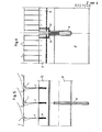
- the valves 1, 7 for gas and steam flows which are shown in FIGS. 1 to 4 and are designed as angle profiles, have two legs 2 and 3 arranged at an angle to one another, of which leg 2 is arranged vertically in the rest position according to FIG. 3 and with its lower, free one End is clamped in a U-profile 4 of a floor surface to be described later.
- the gas flowing in the direction of the arrows 5 exerts a pressure on the underside 6 of the second, horizontally arranged leg 3, which pressure is partially converted into a torque for displacing and bending up the valve.
- a relatively large opening cross section is formed, the gaseous phase being strongly deflected in the upper region, as a result of which great turbulence and intimate contact between the two phases occur.
- valves adjacent in the anchoring direction can be seen in FIG. 2, these adjacent valves being deflected in opposite directions by the gas flow.
- valves shown in Figure 3 in the rest position 1, 7 touch each other in the region of the free end of the second ori h zontal leg 3 and in the angular range.
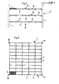
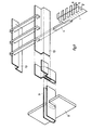
- the mass transfer column 11 has four vertical main supports 12. On this Main supports 12 are anchored several horizontally and at a distance from each other arranged floor surfaces 8.
- the bottom surface 8 is formed from a U-shaped carrier 9 and cross bars 9 '.
- the spars 9 ' are carried by supports 11 which, as can be seen from FIG. 8, extend over the entire width of the mass transfer column 11.
- Angled profiles 10 are inserted into the carrier 9, which have spaced-apart recesses for receiving U-profile elements 4. In these U-profile elements 4, the valves 1, 7 are clamped with the vertical leg 2, the horizontal legs 3 being alternately oriented in opposite directions.
- the VentiLe 1, 7 are made of MetaLL or plastic. They are preferably made of stainless spring steel sheet.
- the thickness of the controls is between 0.05 and 0.25 mm. A preferred range is 0.08 to 0.1 mm.
- the width of the control elements is in the range from 3 to 20 mm, preferably 8 to 12 mm.
Landscapes
- Chemical & Material Sciences (AREA)
- Chemical Kinetics & Catalysis (AREA)
- Vaporization, Distillation, Condensation, Sublimation, And Cold Traps (AREA)
- Physical Or Chemical Processes And Apparatus (AREA)
Applications Claiming Priority (2)
| Application Number | Priority Date | Filing Date | Title |
|---|---|---|---|
| AT0311185A AT389058B (de) | 1985-10-28 | 1985-10-28 | Ventilboden fuer stoffaustauschkolonnen |
| AT3111/85 | 1985-10-28 |
Publications (2)
| Publication Number | Publication Date |
|---|---|
| EP0221048A2 true EP0221048A2 (fr) | 1987-05-06 |
| EP0221048A3 EP0221048A3 (fr) | 1988-07-20 |
Family
ID=3545469
Family Applications (1)
| Application Number | Title | Priority Date | Filing Date |
|---|---|---|---|
| EP86890292A Withdrawn EP0221048A3 (fr) | 1985-10-28 | 1986-10-28 | Elément de réglage pour une colonne |
Country Status (8)
| Country | Link |
|---|---|
| EP (1) | EP0221048A3 (fr) |
| AT (1) | AT389058B (fr) |
| CA (1) | CA1295235C (fr) |
| CS (1) | CS275833B6 (fr) |
| DD (1) | DD250057A5 (fr) |
| HU (1) | HU198132B (fr) |
| PL (1) | PL152536B1 (fr) |
| ZA (1) | ZA867923B (fr) |
Family Cites Families (7)
| Publication number | Priority date | Publication date | Assignee | Title |
|---|---|---|---|---|
| DE67964C (de) * | Firma GEORG HALLER in Altona - Ottensen, I. Bornstr. 31 | Messer - Putzmaschine | ||
| DE1164776B (de) * | 1958-11-21 | 1964-03-05 | Enfo Grundlagen Forschungs Ag | Klappenventil |
| BE622940A (fr) * | 1961-09-29 | 1900-01-01 | ||
| NL284692A (fr) * | 1962-10-19 | |||
| US3940462A (en) * | 1964-06-27 | 1976-02-24 | Chepos Zavody Chemicho A Potravinarskeho Strojirenstvi, Generalni Reditelstvi | Bubble tray and cap assembly for fluid contact apparatus |
| DE1542230A1 (de) * | 1966-05-26 | 1970-05-21 | Ins Tut Fuer Chemieanlagen | Klappenventil fuer Ventilboeden zur Veraenderung des Gas- bzw. Dampfdurchtrittes |
| DE1667347A1 (de) * | 1968-03-15 | 1971-04-08 | Masch Und Appbau Grimma Veb | Klappenboden fuer Stoffaustauschkolonnen |
-
1985
- 1985-10-28 AT AT0311185A patent/AT389058B/de not_active IP Right Cessation
-
1986
- 1986-10-20 ZA ZA867923A patent/ZA867923B/xx unknown
- 1986-10-24 DD DD86295577A patent/DD250057A5/de unknown
- 1986-10-27 PL PL1986262076A patent/PL152536B1/pl unknown
- 1986-10-27 CA CA000521476A patent/CA1295235C/fr not_active Expired - Fee Related
- 1986-10-27 HU HU864504A patent/HU198132B/hu unknown
- 1986-10-28 CS CS867782A patent/CS275833B6/cs unknown
- 1986-10-28 EP EP86890292A patent/EP0221048A3/fr not_active Withdrawn
Also Published As
| Publication number | Publication date |
|---|---|
| ZA867923B (en) | 1987-06-24 |
| DD250057A5 (de) | 1987-09-30 |
| EP0221048A3 (fr) | 1988-07-20 |
| CA1295235C (fr) | 1992-02-04 |
| HUT45909A (en) | 1988-09-28 |
| PL152536B1 (en) | 1991-01-31 |
| HU198132B (en) | 1989-08-28 |
| ATA311185A (de) | 1989-03-15 |
| PL262076A1 (en) | 1987-10-05 |
| AT389058B (de) | 1989-10-10 |
| CS275833B6 (en) | 1992-03-18 |
Similar Documents
| Publication | Publication Date | Title |
|---|---|---|
| DE2060178C3 (de) | Grid-Austauschpackung für Kolonnen | |
| EP0070920B1 (fr) | Colonne pour échange de matière et pour échange directe de chaleur | |
| DE1944420C3 (de) | Geschlossener Reaktor zur Verteilung von abwärtsströmenden Flüssigkeiten | |
| DE69018408T2 (de) | Anordnung zur Stoffverteilung sowie zum Wärme- und Stoffaustausch für eine Kolonne, insbesondere mit Füllkörper und Kolonne mit einer solchen Anordnung. | |
| DE2449383A1 (de) | Gitteranordnung fuer dampf-fluessigkeits-kontaktbehaelter | |
| DE69412578T2 (de) | Hochleistungswanne für gas-flüssigkeitskontaktvorrichtung | |
| DE4006264A1 (de) | Siedewasserkernreaktor und kernreaktorbrennelement fuer diesen siedewasserkernreaktor | |
| DE1544027A1 (de) | Gitter fuer Einrichtungen,in denen Daempfe und Fluessigkeiten miteinander in Beruehrung gebracht werden | |
| EP0151693A2 (fr) | Colonne d'échange de matière | |
| DE68913114T2 (de) | Gas Flüssigkeit-Kontakt. | |
| EP0374443B1 (fr) | Dispositif pour porter des élements de remplissage et pour collecter ou distribuer des liquides dans un récipient échangeur de chaleur ou de masse | |
| EP0221048A2 (fr) | Elément de réglage pour une colonne | |
| EP0517670B1 (fr) | Grille de support pour garnissage dans des colonnes d'échange de matériaux | |
| DE1965230A1 (de) | Gegenstromvorrichtung fuer direkten Kontakt von Fluiden | |
| DE3841642A1 (de) | Duesenrost fuer gaswaescher, absorber und dgl. sowie daraus bestehender kolonneneinbau | |
| DE2901935C2 (de) | Wärme- und Stoffaustauschkolonne | |
| DE3037757A1 (de) | Trennkolonne | |
| DE2554789C3 (de) | Kontaktboden für Kolonnenapparate zur Durchführung von Stoffaustauschprozessen zwischen Gas und Flüssigkeit | |
| DE1519620A1 (de) | Einbauplattenanordnung fuer Rieselkolonnen | |
| DE19622955A1 (de) | Stoffaustauschboden | |
| DE2550023B2 (de) | Entgasungskolonne | |
| CH662515A5 (en) | Built-in element for mass transfer columns | |
| EP0406471B1 (fr) | Elément combustible pour réacteur nucléaire | |
| DE2804680A1 (de) | Rektifikationskolonne mit horizontalen austauschboeden | |
| DE2758902A1 (de) | Mischbehaelter |
Legal Events
| Date | Code | Title | Description |
|---|---|---|---|
| PUAI | Public reference made under article 153(3) epc to a published international application that has entered the european phase |
Free format text: ORIGINAL CODE: 0009012 |
|
| AK | Designated contracting states |
Kind code of ref document: A2 Designated state(s): AT BE CH DE ES FR GB GR IT LI LU NL SE |
|
| PUAL | Search report despatched |
Free format text: ORIGINAL CODE: 0009013 |
|
| AK | Designated contracting states |
Kind code of ref document: A3 Designated state(s): AT BE CH DE ES FR GB GR IT LI LU NL SE |
|
| 17P | Request for examination filed |
Effective date: 19890117 |
|
| 17Q | First examination report despatched |
Effective date: 19900306 |
|
| STAA | Information on the status of an ep patent application or granted ep patent |
Free format text: STATUS: THE APPLICATION IS DEEMED TO BE WITHDRAWN |
|
| 18D | Application deemed to be withdrawn |
Effective date: 19921117 |
|
| RIN1 | Information on inventor provided before grant (corrected) |
Inventor name: KRANEBITTER, FRANZ, DR. Inventor name: PANNING, PETER Inventor name: SCHMID, PETER J. |