EP0221062B1 - Dispositif de regulation pour une pompe volumetrique, en particulier une pompe a palettes - Google Patents
Dispositif de regulation pour une pompe volumetrique, en particulier une pompe a palettes Download PDFInfo
- Publication number
- EP0221062B1 EP0221062B1 EP85903278A EP85903278A EP0221062B1 EP 0221062 B1 EP0221062 B1 EP 0221062B1 EP 85903278 A EP85903278 A EP 85903278A EP 85903278 A EP85903278 A EP 85903278A EP 0221062 B1 EP0221062 B1 EP 0221062B1
- Authority
- EP
- European Patent Office
- Prior art keywords
- throttle
- bore
- regulation device
- flow regulating
- regulating piston
- Prior art date
- Legal status (The legal status is an assumption and is not a legal conclusion. Google has not performed a legal analysis and makes no representation as to the accuracy of the status listed.)
- Expired
Links
- 238000006073 displacement reaction Methods 0.000 title claims abstract description 8
- 230000001105 regulatory effect Effects 0.000 claims 13
- 230000002093 peripheral effect Effects 0.000 description 6
- 210000003734 kidney Anatomy 0.000 description 4
- 238000011161 development Methods 0.000 description 2
- 230000018109 developmental process Effects 0.000 description 2
- 238000013459 approach Methods 0.000 description 1
- 230000007423 decrease Effects 0.000 description 1
- 230000003247 decreasing effect Effects 0.000 description 1
- 230000001419 dependent effect Effects 0.000 description 1
- 238000010586 diagram Methods 0.000 description 1
- 230000000694 effects Effects 0.000 description 1
- 239000012530 fluid Substances 0.000 description 1
- 238000001746 injection moulding Methods 0.000 description 1
- 238000009434 installation Methods 0.000 description 1
- 238000004519 manufacturing process Methods 0.000 description 1
- 239000000463 material Substances 0.000 description 1
- 238000010079 rubber tapping Methods 0.000 description 1
- 239000000243 solution Substances 0.000 description 1
- 230000003068 static effect Effects 0.000 description 1
Images
Classifications
-
- F—MECHANICAL ENGINEERING; LIGHTING; HEATING; WEAPONS; BLASTING
- F04—POSITIVE - DISPLACEMENT MACHINES FOR LIQUIDS; PUMPS FOR LIQUIDS OR ELASTIC FLUIDS
- F04C—ROTARY-PISTON, OR OSCILLATING-PISTON, POSITIVE-DISPLACEMENT MACHINES FOR LIQUIDS; ROTARY-PISTON, OR OSCILLATING-PISTON, POSITIVE-DISPLACEMENT PUMPS
- F04C14/00—Control of, monitoring of, or safety arrangements for, machines, pumps or pumping installations
- F04C14/24—Control of, monitoring of, or safety arrangements for, machines, pumps or pumping installations characterised by using valves controlling pressure or flow rate, e.g. discharge valves or unloading valves
- F04C14/26—Control of, monitoring of, or safety arrangements for, machines, pumps or pumping installations characterised by using valves controlling pressure or flow rate, e.g. discharge valves or unloading valves using bypass channels
Definitions
- the invention relates to a control device according to the kind described in the preamble of claim 1.
- Vane pumps in particular are very often used for supplying pressurized oil to power steering systems.
- To regulate the flow rate for power steering it is known to narrow the pressure channel in the area of the tapping point. This measure results in a higher flow velocity and thus a reduction in the static pressure on the rear side of the flow control piston.
- the differential pressure between the two piston surfaces increases and the flow control piston experiences a speed-dependent opening tendency, so that the inlet opening in the flow return line is released to a corresponding extent.
- a «falling characteristic of the vane pump is thus achieved; d. H. the volume throughput is not increased further according to the performance of the vane pump from a certain cut-off point, but may even be reduced.
- control slide is designed as a bow spring which is attached to the front of the flow control piston.
- the free end of the bow spring correspondingly covers the throttle bore (s).
- the object of the present invention is to create even more possible variations in comparison to this previously known solution with regard to the characteristic curves.
- the inventive arrangement of the throttle bore or throttle bores in cooperation with the throttle plate means that numerous characteristic curve variants can be set without problems. To do this, it is only necessary to provide corresponding control slides. Another advantage is that this configuration is very simple and safe. Since there is a parallel displacement of the throttle plate to the displacement of the flow control piston and no bow spring is necessary, there is no risk of permanent failure. Furthermore, the control slide with the throttle plate can be produced easily and inexpensively.
- the throttle device and the flow control piston are parallel to each other and that the throttle bore is arranged in a peripheral wall of the throttle device.
- control slide no longer has to be firmly attached to the end face, but can, for. B. may be arranged in a transverse bore in the flow control piston. This means that a rigid attachment to the piston is not necessary and the control slide can be easily assembled or disassembled. In this way, changes to the characteristic are still possible without problems, or the control device can be manufactured in series and then adapted to the respective requirements by means of a corresponding control slide.
- the throttle device can have a cylindrical shape at least in the region of the throttle bore.
- the throttle plate will advantageously be at least approximately designed as a segment of a hollow cylindrical shape, the inner diameter of which is at least approximately matched to the outer diameter of the throttle device.
- the throttle plate of the control slide is always free of play on the throttle device and the distance between the throttle device and the flow control piston can also be designed with large tolerances
- the throttle plate can be pressed against the peripheral wall of the throttle device by a spring.
- it can lie behind a pin of the control slide in a transverse bore designed as a blind bore or it is clamped between the underside of the throttle plate and the peripheral wall of the flow control piston.
- the throttle device can also have a collar at the front end facing the pressure chamber. This collar serves to facilitate assembly and secures at the same time also that the throttle plate is held on the throttle device. In this way, additional security measures are unnecessary.
- throttle bore is offset circumferentially from the throttle plate, further characteristic curve characteristics can be set.
- further characteristic curve characteristics can be set.
- the throttle bore or the throttle bores can be given any shape.
- the throttle plate, in coordination with the throttle bore can have any shape in plan view, so that there are corresponding possible variations.
- the throttle device has, in addition to the throttle bore, a bore with an unchangeable cross section for the passage of the pressure medium.
- control slide can be provided with a notch, a cam or the like in the area of its web between the throttle plate and the flow control piston. In this way, there is a point of attack for installation or removal.
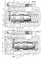
- the vane pump is essentially of a known structure, which is why only the parts essential to the invention are shown and described here.
- the pump has a rotor with wings in the usual way, the rotor being arranged between a front end plate (not shown) and a rear pressure plate 1. Behind the pressure plate 1 there is a pressure chamber 24 which is connected to pressure kidneys (not shown) via pressure bores.
- the pressurized pressure medium passes after passing through a throttle device 2 to an outlet opening 3, from which a line to a consumer, for. B. to power steering.
- the throttle device 2 has a throttle insert in the form of a cylinder.
- a throttle bore 4 and a fixed bore 5 are arranged in the peripheral wall.
- the bores 4 and 5 are used to connect the pressure chamber 2 to the outlet opening 3, the throttle insert 2 being provided with a longitudinal bore 6 for this purpose.
- a flow control piston 7 protrudes into the pressure chamber 24 with its front face, the back of the pressure plate 1 also forming an end stop.
- the flow control piston 7 is arranged displaceably in a bore in the housing or the cover of the vane pump.
- the rear piston surface of the flow control piston 7 lies in a spring chamber 8 of the bore, in which a spring 9 is arranged, which exerts a closing force on the flow control piston 7 in the direction of the pressure plate 1.
- the spring chamber 8 is connected via a transverse bore 10 to a pressure chamber 11, which is located behind the throttle device 2.
- the flow control piston 7 is provided with a control edge 12, behind which there is an inlet opening 13 with an adjoining flow return line 14.
- the throttle device 2 and the flow control piston 7 are parallel to each other.
- the center line of the throttle bore 4 is perpendicular to the longitudinal axis of the flow control piston 7.
- a control slide 15 consists of a throttle plate 16 and a web 17.
- the web 17 is mounted in a transverse bore 18 of the flow control piston 7.
- the transverse bore 18 is designed as a blind bore and a spring 19 is stretched between the bottom of the blind bore 18 and the rear end of the web 17. In this way, the throttle plate is always pressed against the peripheral wall of the throttle device 2.
- the throttle plate 16 forms a segment of a hollow cylindrical shape, the inner diameter of which is at least approximately matched to the outer diameter of the throttle device. In this way, a good seal or throttling is provided. Furthermore, the control slide 15 also forms an anti-rotation device for the flow control piston 7.
- the control slide can be simple and inexpensive, for. B. from pressure or injection molding. Also different materials, such as. B. plastic, possible.
- a plurality of throttle bores can optionally also be arranged one behind the other in the longitudinal direction or in the circumferential direction in the throttle device 2.
- Several throttle bores arranged one behind the other or next to one another can also be combined to form an elongated hole.
- Throttle bores can also be offset on the circumference of the throttle plate 16. In this way, partial coverage may be possible and thus also a certain independence from the piston travel.
- a pressure kidney 20, via which the pressure chamber 24 is supplied with pressure oil is indicated by dashed lines.
- the cylindrical throttle device 2 has a collar 21 at the front end projecting into the pressure chamber 24, which collar forms a stop for the pressure plate 16. Furthermore, the web 17 of the control slide 15 can be provided in its free area with a notch 22 (shown in dashed lines in FIG. 1). In this way, a point of attack for easier assembly and disassembly is formed.
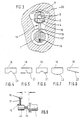
- FIGS. 4-8 are only to be regarded as part of a multitude of possibilities. Depending on the application and the desired curve, there are numerous possible variations.
- the bore 5 serves to improve the cold start behavior. In this case it works alone in the open position and the risk of cavitation is reduced due to the low flow rate.
- a continuous transverse bore can optionally also be used. In this way there is symmetry and no assembly errors can occur.
- the spring 19 is then arranged between the underside of the throttle plate 16 and the peripheral wall of the flow control piston 7 above the web 17.
- the longitudinal bore 6 in the throttle device can be dimensioned such that it determines the cut-off point. All that is required for this is that the flow cross sections of the throttle bore 4 and the bore 5 together are larger than the flow cross section of the longitudinal bore 6.
- this hole can also be used to influence the characteristic curve itself. Depending on their size, they can influence the "falling" tendency of the characteristic curves.
- control slide 15 has a base part 25 with a thread in the lower region debolzen 26.
- the web 17 is also inserted into a transverse bore of the base part 25, or it is integrally formed with this.
- the front end face of the flow control piston 7 has a threaded hole into which the threaded bolt 26 of the control slide 15 can be screwed.
Landscapes
- Engineering & Computer Science (AREA)
- Physics & Mathematics (AREA)
- Fluid Mechanics (AREA)
- Mechanical Engineering (AREA)
- General Engineering & Computer Science (AREA)
- Details And Applications Of Rotary Liquid Pumps (AREA)
- Rotary Pumps (AREA)
Abstract
Claims (17)
Applications Claiming Priority (2)
| Application Number | Priority Date | Filing Date | Title |
|---|---|---|---|
| WOPCT/EP84/00214 | 1984-07-12 | ||
| EP8400214 | 1984-07-12 |
Publications (2)
| Publication Number | Publication Date |
|---|---|
| EP0221062A1 EP0221062A1 (fr) | 1987-05-13 |
| EP0221062B1 true EP0221062B1 (fr) | 1989-03-15 |
Family
ID=8164951
Family Applications (1)
| Application Number | Title | Priority Date | Filing Date |
|---|---|---|---|
| EP85903278A Expired EP0221062B1 (fr) | 1984-07-12 | 1985-07-06 | Dispositif de regulation pour une pompe volumetrique, en particulier une pompe a palettes |
Country Status (3)
| Country | Link |
|---|---|
| EP (1) | EP0221062B1 (fr) |
| DE (1) | DE3524413A1 (fr) |
| WO (1) | WO1986000671A1 (fr) |
Cited By (1)
| Publication number | Priority date | Publication date | Assignee | Title |
|---|---|---|---|---|
| DE4101210A1 (de) * | 1990-01-17 | 1991-07-18 | Zahnradfabrik Friedrichshafen | Regeleinrichtung fuer verdraengerpumpen |
Families Citing this family (3)
| Publication number | Priority date | Publication date | Assignee | Title |
|---|---|---|---|---|
| DE3909159A1 (de) * | 1988-03-25 | 1989-10-05 | Zahnradfabrik Friedrichshafen | Regeleinrichtung fuer verdraengerpumpen |
| JP2852476B2 (ja) * | 1990-07-20 | 1999-02-03 | ツァーンラトファブリック フリードリッヒシャーフェン アクチェンゲゼルシャフト | 排油ポンプの制御機構 |
| DE102005043253B4 (de) * | 2005-09-09 | 2014-09-04 | Zf Lenksysteme Gmbh | Verfahren zum Herstellen einer Verdrängerpumpe und eine danach hergestellte Verdrängerpumpe |
Citations (1)
| Publication number | Priority date | Publication date | Assignee | Title |
|---|---|---|---|---|
| DE3211948A1 (de) * | 1982-03-31 | 1983-10-20 | Zahnradfabrik Friedrichshafen Ag, 7990 Friedrichshafen | Regelbare fluegelzellenpumpe |
Family Cites Families (3)
| Publication number | Priority date | Publication date | Assignee | Title |
|---|---|---|---|---|
| DE1653503B2 (de) * | 1966-07-01 | 1976-12-02 | Lucas Industries Ltd., Birmingham (Grossbritannien) | Vorrichtung zur regelung der foerdermenge einer hydrostatischen verstellpumpe |
| FR2194241A5 (fr) * | 1972-07-20 | 1974-02-22 | Sonnberger Felix | |
| US4361166A (en) * | 1980-01-24 | 1982-11-30 | Toyoda Koki Kabushiki Kaisha | Flow controlling apparatus for power steering, operating fluid |
-
1985
- 1985-07-06 EP EP85903278A patent/EP0221062B1/fr not_active Expired
- 1985-07-06 WO PCT/EP1985/000332 patent/WO1986000671A1/fr not_active Ceased
- 1985-07-09 DE DE19853524413 patent/DE3524413A1/de not_active Withdrawn
Patent Citations (1)
| Publication number | Priority date | Publication date | Assignee | Title |
|---|---|---|---|---|
| DE3211948A1 (de) * | 1982-03-31 | 1983-10-20 | Zahnradfabrik Friedrichshafen Ag, 7990 Friedrichshafen | Regelbare fluegelzellenpumpe |
Cited By (2)
| Publication number | Priority date | Publication date | Assignee | Title |
|---|---|---|---|---|
| DE4101210A1 (de) * | 1990-01-17 | 1991-07-18 | Zahnradfabrik Friedrichshafen | Regeleinrichtung fuer verdraengerpumpen |
| DE4101210C2 (de) * | 1990-01-17 | 1998-10-08 | Zahnradfabrik Friedrichshafen | Regeleinrichtung für Verdrängerpumpen |
Also Published As
| Publication number | Publication date |
|---|---|
| EP0221062A1 (fr) | 1987-05-13 |
| WO1986000671A1 (fr) | 1986-01-30 |
| DE3524413A1 (de) | 1986-01-23 |
Similar Documents
| Publication | Publication Date | Title |
|---|---|---|
| DE4428667C2 (de) | Kombiniertes Stromregel- und Druckregelventil für eine Pumpe und mit patronenförmigem Ventilgehäuse | |
| DE3733102C2 (fr) | ||
| DE3313390A1 (de) | Oelpumpenanordnung | |
| EP0782672B1 (fr) | Systeme de regulation pour pompes de refoulement | |
| DE3802904A1 (de) | Servounterstuetzte lenkanlage | |
| EP0221062B1 (fr) | Dispositif de regulation pour une pompe volumetrique, en particulier une pompe a palettes | |
| DE69009254T2 (de) | Hydraulische Kupplung. | |
| DE3508775C2 (fr) | ||
| EP1259737B1 (fr) | Dispositif de regulation pour pompes volumetriques | |
| DE3211948C2 (de) | Regeleinrichtung für eine Verdrängerpumpe, insbesondere Flügelzellenpumpe | |
| DE102008033073B3 (de) | Zentrifugalpumpe | |
| DE4108126C2 (de) | Flügelzellenpumpe | |
| EP1378665B1 (fr) | Pompe à palettes | |
| DE4101210C2 (de) | Regeleinrichtung für Verdrängerpumpen | |
| DE2402017A1 (de) | Rotationskolbenpumpe, insbesondere fuer servolenkungen von kraftfahrzeugen | |
| DE2753098C2 (de) | Lenkanlage mit hydraulischer Hilfskraftunterstützung | |
| EP1025363B1 (fr) | Pompe volumetrique | |
| EP0528254B1 (fr) | Dispositif de régulation pour pompes à déplacement positif | |
| DE1675469A1 (de) | Stromregelventil | |
| EP1318304B1 (fr) | Pompe à palettes | |
| EP0199833B1 (fr) | Pompe hydraulique | |
| DE69010631T2 (de) | Verdrängerpumpe-Anlagen. | |
| DE3701271C2 (de) | Vorrichtung zum fahrgeschwindigkeitsabhängigen Verändern der Unterstützungswirkung einer Servolenkung | |
| DE3249477C2 (de) | Hydraulische Hilfskraftlenkeinrichtung f}r Kraftfahrzeuge | |
| DE7011867U (de) | Pumpe mit steuervorrichtung. |
Legal Events
| Date | Code | Title | Description |
|---|---|---|---|
| PUAI | Public reference made under article 153(3) epc to a published international application that has entered the european phase |
Free format text: ORIGINAL CODE: 0009012 |
|
| 17P | Request for examination filed |
Effective date: 19861028 |
|
| AK | Designated contracting states |
Kind code of ref document: A1 Designated state(s): DE IT |
|
| 17Q | First examination report despatched |
Effective date: 19880603 |
|
| ITF | It: translation for a ep patent filed | ||
| GRAA | (expected) grant |
Free format text: ORIGINAL CODE: 0009210 |
|
| AK | Designated contracting states |
Kind code of ref document: B1 Designated state(s): DE IT |
|
| REF | Corresponds to: |
Ref document number: 3568832 Country of ref document: DE Date of ref document: 19890420 |
|
| PLBE | No opposition filed within time limit |
Free format text: ORIGINAL CODE: 0009261 |
|
| STAA | Information on the status of an ep patent application or granted ep patent |
Free format text: STATUS: NO OPPOSITION FILED WITHIN TIME LIMIT |
|
| 26N | No opposition filed | ||
| ITTA | It: last paid annual fee | ||
| PGFP | Annual fee paid to national office [announced via postgrant information from national office to epo] |
Ref country code: DE Payment date: 19940819 Year of fee payment: 10 |
|
| PG25 | Lapsed in a contracting state [announced via postgrant information from national office to epo] |
Ref country code: DE Effective date: 19960402 |