EP0221111B1 - Procede de correction des couleurs d'images numeriques - Google Patents
Procede de correction des couleurs d'images numeriques Download PDFInfo
- Publication number
- EP0221111B1 EP0221111B1 EP86902734A EP86902734A EP0221111B1 EP 0221111 B1 EP0221111 B1 EP 0221111B1 EP 86902734 A EP86902734 A EP 86902734A EP 86902734 A EP86902734 A EP 86902734A EP 0221111 B1 EP0221111 B1 EP 0221111B1
- Authority
- EP
- European Patent Office
- Prior art keywords
- color
- values
- red
- blue
- reproduction functions
- Prior art date
- Legal status (The legal status is an assumption and is not a legal conclusion. Google has not performed a legal analysis and makes no representation as to the accuracy of the status listed.)
- Expired
Links
- 238000000034 method Methods 0.000 title claims abstract description 34
- 238000012937 correction Methods 0.000 title description 3
- 230000006870 function Effects 0.000 claims abstract description 126
- 239000003086 colorant Substances 0.000 claims abstract description 15
- 238000009826 distribution Methods 0.000 claims description 22
- 230000007935 neutral effect Effects 0.000 claims description 15
- 238000012417 linear regression Methods 0.000 claims description 6
- 238000003672 processing method Methods 0.000 claims description 6
- 230000004044 response Effects 0.000 claims description 6
- 230000005457 Black-body radiation Effects 0.000 claims 1
- 238000012545 processing Methods 0.000 abstract description 12
- 229920006395 saturated elastomer Polymers 0.000 abstract description 6
- 244000025254 Cannabis sativa Species 0.000 abstract description 5
- 238000005070 sampling Methods 0.000 abstract description 5
- 238000007639 printing Methods 0.000 abstract description 3
- 230000015654 memory Effects 0.000 description 6
- 230000008569 process Effects 0.000 description 5
- 230000003595 spectral effect Effects 0.000 description 5
- 230000006872 improvement Effects 0.000 description 4
- 239000000654 additive Substances 0.000 description 3
- 230000000996 additive effect Effects 0.000 description 3
- 238000010586 diagram Methods 0.000 description 3
- 230000035945 sensitivity Effects 0.000 description 3
- 238000000926 separation method Methods 0.000 description 3
- 230000001419 dependent effect Effects 0.000 description 2
- 238000009499 grossing Methods 0.000 description 2
- 230000008520 organization Effects 0.000 description 2
- 239000007787 solid Substances 0.000 description 2
- 238000012935 Averaging Methods 0.000 description 1
- 238000013459 approach Methods 0.000 description 1
- 238000003491 array Methods 0.000 description 1
- 230000006399 behavior Effects 0.000 description 1
- 238000004364 calculation method Methods 0.000 description 1
- 230000000694 effects Effects 0.000 description 1
- 238000005516 engineering process Methods 0.000 description 1
- 230000001747 exhibiting effect Effects 0.000 description 1
- 238000007667 floating Methods 0.000 description 1
- 238000005286 illumination Methods 0.000 description 1
- 238000003384 imaging method Methods 0.000 description 1
- 238000013383 initial experiment Methods 0.000 description 1
- 238000012886 linear function Methods 0.000 description 1
- 238000005259 measurement Methods 0.000 description 1
- 238000010606 normalization Methods 0.000 description 1
- 238000005293 physical law Methods 0.000 description 1
- 230000005855 radiation Effects 0.000 description 1
- 239000004065 semiconductor Substances 0.000 description 1
- 238000009966 trimming Methods 0.000 description 1
- WFKWXMTUELFFGS-UHFFFAOYSA-N tungsten Chemical compound [W] WFKWXMTUELFFGS-UHFFFAOYSA-N 0.000 description 1
- 229910052721 tungsten Inorganic materials 0.000 description 1
- 239000010937 tungsten Substances 0.000 description 1
- 230000000007 visual effect Effects 0.000 description 1
- 230000016776 visual perception Effects 0.000 description 1
Images





Classifications
-
- H—ELECTRICITY
- H04—ELECTRIC COMMUNICATION TECHNIQUE
- H04N—PICTORIAL COMMUNICATION, e.g. TELEVISION
- H04N1/00—Scanning, transmission or reproduction of documents or the like, e.g. facsimile transmission; Details thereof
- H04N1/46—Colour picture communication systems
- H04N1/56—Processing of colour picture signals
- H04N1/60—Colour correction or control
- H04N1/6083—Colour correction or control controlled by factors external to the apparatus
- H04N1/6086—Colour correction or control controlled by factors external to the apparatus by scene illuminant, i.e. conditions at the time of picture capture, e.g. flash, optical filter used, evening, cloud, daylight, artificial lighting, white point measurement, colour temperature
-
- H—ELECTRICITY
- H04—ELECTRIC COMMUNICATION TECHNIQUE
- H04N—PICTORIAL COMMUNICATION, e.g. TELEVISION
- H04N1/00—Scanning, transmission or reproduction of documents or the like, e.g. facsimile transmission; Details thereof
- H04N1/46—Colour picture communication systems
- H04N1/56—Processing of colour picture signals
- H04N1/60—Colour correction or control
- H04N1/6027—Correction or control of colour gradation or colour contrast
-
- H—ELECTRICITY
- H04—ELECTRIC COMMUNICATION TECHNIQUE
- H04N—PICTORIAL COMMUNICATION, e.g. TELEVISION
- H04N1/00—Scanning, transmission or reproduction of documents or the like, e.g. facsimile transmission; Details thereof
- H04N1/46—Colour picture communication systems
- H04N1/56—Processing of colour picture signals
- H04N1/60—Colour correction or control
- H04N1/603—Colour correction or control controlled by characteristics of the picture signal generator or the picture reproducer
-
- H—ELECTRICITY
- H04—ELECTRIC COMMUNICATION TECHNIQUE
- H04N—PICTORIAL COMMUNICATION, e.g. TELEVISION
- H04N1/00—Scanning, transmission or reproduction of documents or the like, e.g. facsimile transmission; Details thereof
- H04N1/46—Colour picture communication systems
- H04N1/56—Processing of colour picture signals
- H04N1/60—Colour correction or control
- H04N1/6094—Colour correction or control depending on characteristics of the input medium, e.g. film type, newspaper
Definitions
- the present invention relates to a method of processing digital color images derived from photographic film, and more particularly to such a method employing a plurality of color reproduction functions generated by normalizing samples of color values selected from the informational portions of the image, the color reproduction functions being applied to the digital color image to produce a processed digital color image.
- a digital image processing method has been proposed wherein a random sample of tone values from the informational portion of the digital image is normalized to produce a tone reproduction function. The tone reproduction function is then applied to the digital image to produce a processed digital image.
- This procedure was first proposed in the article entitled "A New Approach to Programming in Photomechanical Reproduction” by Yu. Ovchinnikov et al, 12th IARIGAI Conference Proceedings, Why, France, Editor W. Banks, IPC Science and Technology Press, Guildford, England, 1974, pages 160-163. It has been discovered that the success of the method depends strongly upon choosing a truly random sample of tone values from the image.
- This method generally produces an aesthetic improvement in the appearance of processed color images, however when the digital color image is derived from a color photographic film image containing highly saturated textures such as large areas of green grass or noisy blue sky, the randomness of the sampling procedure for producing the samples of color values for normalization is subject to influence, thereby distorting the color reproduction functions and causing unwanted color shifts in the processed images.
- the object of the invention is achieved by a method of producing a digitalized color image derived from photographic film, by applying color reproduction functions to the color components of the digital image, characterized by the step of constraining the color reproduction functions in conformance with the response of the photographic film as represented by the film D-Log H curves and in conformance with the behavior of said photographic film when the original scene is illuminated by a black body radiator at some particular color temperature.
- Fig. 2 is a graph showing how a color reproduction function is generated.
- the upper left-hand quadrant of the graph shows a histogram labeled A of a sample of color values (photographic densities) taken from an informational portion of the image. The sample is plotted against relative frequency of occurrence.
- the lower right-hand quadrant of the graph shows a histogram labeled B of a normal (Gaussian) distribution showing the relative frequency of occurrence vs the standard normal variate Z.
- the standard variate Z is a scale in units of standard deviations of a Gaussian distribution.
- a function labeled C that converts the distribution of the measured sample of color values to the normal distribution.
- This function relates any given color value in the measured distribution to a value of Z.
- the Z value is a dimensionless quantity representing numbers of standard deviations.
- the measured color values in the digital color image are converted to Z values using the color reproduction function.
- the resulting dimensionless quantities are given dimension by multiplying the Z values by a constant to determine the contrast of the processed image, and adding a constant to the Z values in the respective colors to adjust the color balance of the processed image.
- the additive constants are chosen such that equal Z values in all three colors produce a neutral (gray) color.
- red, green and blue color reproduction functions be consistent with the corresponding D-log H curves of the color photographic film.
- the color reproduction functions should also have linear relationships between the red, green and blue color reproduction functions.
- Another constraint is based upon the observation that the commonly used light sources for color photography can be approximated by blackbody radiators at different color temperatures. This implies certain restrictions on the relationship between the color reproduction functions.
- the D-Log H curves of a color negative film usually have a large straight line portion above the base plus fog densities
- Fig. 3 shows an example for Kodak VR 200 film in red, green and blue status M densities.
- the D-Log H curves can be approximated by straight lines, and the error will mostly occur in the toe regions of the curves, where colors are not readily perceived by a human observer.
- D-Log H curves be approximated by: where D r , Dg, D b , H r , Hg and H b are red, green and blue densities and exposures respectively, A r , Ag and A b are the slopes of the D-Log H curves, and B,, B g and B b are the intercepts.
- Equations (10) and (11), show that if the red, green and blue densities of a neutral surface are measured under a given illuminant, the green and blue densities will be linear functions of the red density.
- the slopes Sg r and S br depend only on the film type, and the intercepts I gr and I br are functions of both the film type and the illuminant.
- I gr and I br can be determined for a given image.
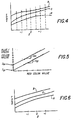
- Fig. 4 shows an example of the color reproduction functions generated for a particular image. Several arbitrarily selected neutral points on the curves at equal Z values representing estimated neutral points in the image are indicated. In Fig. 5, the green and blue color values are shown plotted (dashed lines) against the red color values for each neutral point. A line having a slope equal to S br is fit by linear regression through the points representing blue/red values. The intersection of the line with the blue axis is the value I br . Similarly, a line having a slope equal to S gr is fitted by linear regression through the points representing the green/red values. The intersection of this line with the green axis is the value Ig r .
- Equations (10) and (11) are rewritten as follows: where D' r and D' b are the corrected values of the red and blue color reproduction functions, and Dg is the value of the green color reproduction function at any given Z value.
- the D-Log H linear constraint is used to reshape the blue and red color reproduction functions using the green color reproduction function as a reference.
- Fig. 6 shows the corrected color reproduction functions generated from the color reproduction functions shown in Fig. 4 by applying the D-Log H linear constraint.
- the spectral energy distribution of a photographic light source is often specified by the so-called color temperature.
- the idea is to approximate the spectral energy distribution of a light source by that of an ideal black body radiator at a particular temperature. This approximation is very good for tungsten lamps, reasonably good for daylight and photographic flash bulbs, and not so good for fluorescent lamps.
- a constraint on the relationship between the color reproduction functions from a photographic film image can be derived as follows.
- equation (15) can be approximated by: where and
- S r ( ⁇ ), Sg( ⁇ ) and S b ( ⁇ ) be the spectral sensitivity functions of the red, green and blue layers of the film respectively, and let them have a normalized area of 1. Then the effective image irradiance is related to the energy through the film sensitivity by: similarly, where effective mean wavelengths of the red, green and blue layers of the film. Where the red exposure H r , for example is the effective image irradiance E r times the exposure time ⁇ t.
- equations (17)-(19) are of the same form as equation (16) for the purpose of calculating red, green and blue exposures of a given film, each film layer can be represented with a single wavelength, and different light sources will be represented as black body radiators at different temperatures T. Therefore, one can write: where ⁇ r , ⁇ g and ⁇ b are functions of the film type and other factors involved in the imaging and measuring process.
- equation (23) shows that there is a linear constraint on the color of various light sources which can be approximated by black body radiators.
- I gr and I br are computed, as described above with reference to the D-Log H linear constraint, for a number of images from a given film type.
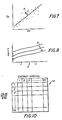
- Fig. 7 shows a plot of Ig, vs. I b , for such a collection of images. A straight line is fit through the resulting collection of points using the least squares fit method. If the point (I gr , I b ,) of an input image lies very far from this line, it is assumed that the estimated neutral densities have been biased by oversampling of a highly saturated color.
- Fig. 8 shows an example of the corrected color reproduction functions using both the D-Log H linear constraint and the illuminant constraint.
- the correction for illuminant color can be less than the full amount needed to bring the point (I gr , I br ) all the way back to the illuminant line, since the illuminant constraint does not take into account the mutual illumination among objects, and the black body approximation may not be entirely accurate.
- the D-Log H linear constraint corrects the shapes of the color reproduction functions
- the illuminant constraint corrects the separation distance between the color reproduction functions. If oversampling of a saturated color occurs in a fairly narrow density range, the shape of the reproduction function is distorted in that range.
- the D-Log H linear constraint will reshape the red and blue color reproduction functions according to equations (12) and (13), taking the green color reproduction function as a reference. Because the green color reproduction function is comparatively more stable than the other two, under different illuminants, it is taken as the reference, and its shape is left unchanged.
- the illuminant constraint by shifting the relative distances between the color reproduction functions, corrects the color balance errors in the direction perpendicular to the illuminant line (green vs magenta). Errors in the direction of the illuminant line (red-yellow vs cyan-blue) are not corrected by this constraint. However, it should be noted that human visual perception is less sensitive to color errors in this direction.
- the color problems most commonly encountered in the digital color image processing method employing the color reproduction functions generated by normalizing random samples of color values, i.e. oversampling due to green grass textures and blue sky noise are corrected by applying the constraints outlined above.
- the illuminant constraint corrects the green-magenta color error
- the D-Log H constraint corrects the shape distortion of the tone reproduction curves from oversampling the high density blue sky areas.
- a scanner 10 scans a color film image to provide a digital color image signal having three color components R, G and B.
- a digital computer 12 receives the digital color image signal and is programmed, as described below, to provide a sampler and histogram compiler 14 for sampling the color values from the informational portion (edges) of the digital image and compiling histograms H R , He, and H B of the sampled color values in the respective colors.
- a histogram normalizer 16 receives the histogram data H R , H G , and H B and generates a set of functions Z,, Zg and Z b that normalize the respective histograms.
- the functions Z" Zg and Z b are the color reproduction functions graphically illustrated in Fig. 4.
- a constrained corrector 18 receives the color reproduction functions, and a set of constraints (e.g. Sg r and S br as defined in equations (6) and (7) above) for the image being processed, and corrects the color reproduction functions in conformance with the constraints.
- the constrained corrector 18 produces as an output, a set of corrected color reproduction functions Z' r , Zg' and Z' b .
- the digital color image is then processed using the corrected color reproduction functions.
- the input device includes a light source 20 and lens 22'for projecting an image of color negative film 24 onto three solid state image sensing arrays 26, such as CCD image sensors.
- the image is directed to the image sensing array 26 by dichroic beam splitters 28 through color trimming filters 30, to form a red, green and blue separation image on the respective image sensors 26.
- a film advance motor 31 advances the film in the printer.
- the image sensors 26 scan the color photographic negatives to produce three color separation signals R, G and B.
- the signals thus produced are supplied to analog-to-digital converters 32 that each produce an 8-bit output code representing one of 256 possible signal levels for each sample point in the three colors.
- the digital color image signals are stored in a digital image storage memory 34, such as a magnetic tape, disc, or solid state semiconductor memory.
- the digital color image signals were processed in a digital computer 36, a DEC 2060 mainframe computer was used in the initial experiments, later a special purpose digital image processing computer was used to increase the processing speed.
- the digital computer 36 is programmed to include a color reproduction function generator 38 and a digital image processor 40 that applies color reproduction functions generated by color reproduction function generator 38 to the digital color image.
- the color reproduction function generator 38 receives the color digital image from the digital image storage device 34 via data and a color bus 35 and generates a color reproduction function for each color.
- the color reproduction functions are supplied to the digital image processor 40 as color reproduction function look-up tables 42 that are used to process the digital color image.
- the color reproduction function generator 38 also generates a multiplicative constant ⁇ z for adjusting the contrast of the processed image as described below and supplies the constant to output calibration tables 44 in the digital image processor 40.
- each input signal level Prior to storing the digital color image in digital image store 34, each input signal level is converted to an input color value (such as photographic density), by a known scanner calibration function.
- the calibration function for each color is implemented in the form of a look up input calibration table 46 in the digital image processor 40, to convert each 8-bit input value to an 8-bit value representing the color negative density at the scanning point.
- the color reproduction function generator 38 includes digital filters 48 for performing a block average of the color values of the digital color image.
- Digital filters 50 detect the contrast of the image around each block averaged color value in each of the three colors.
- a histogram compiler 52 compiles the block averaged color values from a plurality of contrast intervals in each color, in a plurality of histogram memories 54.
- Fig. 10 shows, in a graphic way, the organization of one of the histogram memories 54 for one of the colors.
- the width of the contrast intervals was chosen to be approximately twice the minimum visual log contrast threshold.
- the 256 color values are divided into 80 tone color value (density) bins, for a resolution of .05 density units per bin. Counts are accumulated in the appropriate color value bins in the histogram memories 54 until all of the color values from the digital color image are counted.
- a statistics computer 56 computes the first four standardized statistical moments p of the distributions of color values in the histogram memories 54 as described below.
- a contrast interval selector 58 selects a contrast interval on the basis of the statistics of the distributions of color values in the contrast intervals.
- the contrast interval selector 58 supplies the histograms from the selected contrast interval to a histogram normalizer 60.
- Histogram normalizer 60 normalizes the histograms of color values from the selected contrast interval to generate the color reproduction functions Z r , Zg and Z b .
- a constrained corrector 62 receives the color reproduction functions Z r , Zg and Z b , and operator input constraints S br and Sg r and corrects the color reproduction functions in correspondence with the constraints.
- the corrected color reproduction functions Z',, Z'g and Z' b are supplied as look-up table values to the color reproduction function look-up tables 42 in the digital image processor.
- a contrast adjustment computer 64 receives the statistics ⁇ G of the green distribution from the contrast interval selector 58 and produces a multiplicative constant ⁇ z used to determine the contrast of the processed image.
- the multiplicative constant ⁇ z is provided to the output device calibration tables 44.
- the multiplicative constant ⁇ z can be incorporated into the color reproduction function tables 42.
- the color reproduction function look-up tables 42 relate each of the 256 possible input values in the respective colors to one of the 256 possible output values.
- the ' digital image processor 40 processes the digital image by applying the color reproduction functions to the respective color components of the digital color image.
- the output calibration functions are then applied to the respective color components of the processed digital color image.
- the processed digital color image is converted to analog form by digital-to-analog converters 66.
- the processed analog color signal is then applied to an output scanning device 68 to reproduce the processed color image.
- the output device 68 is a drum-type scanner having red, green and blue laser light sources 70 that are modulated by the respective analog color signals to expose a light sensitive medium such as color photographic paper.
- System control electronics 72 controls and coordinates the operation of input and output scanning devices and the signal processing computer and receives the operator input of the constraints S b , and S gr for use by the constrained corrector 62.
- a block average of the color values of the sampled digital image is formed. This is accomplished by applying a digital filter to the digital image color values of the form:
- This averaging is performed by the block average filters 48, shown in Fig. 9 to reduce the effects of film grain on the color value statistics.
- a digital filter representing a Laplacian operator of the form is applied to the block averaged color values of the digital color image to measure the contrast of the image at each block averaged sample point.
- This operation is performed by the contrast measurement filter 50 in Fig. 9.
- the Laplacian operator has the properties of exhibiting no response to uniform areas or linear gradients, and exhibits a response only to changes in gradients. The Laplacian operator works well in measuring the contrast of the image, however it is to be understood that other contrast measuring filters may be employed.
- a contrast interval is selected on the basis of the statistical parameters of the color value distributions in the contrast interval, and the histograms of color values in the selected contrast interval are normalized to generate the respective color reproduction functions for each color.
- the color reproduction functions are then corrected by applying constraints according to the present invention, and an overall contrast adjustment parameter Oz is calculated as a function of the standard deviation of the green color values in the selected contrast interval.
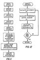
- Fig. 12 is a flow chart showing the steps involved in compiling the histogram statistics for each contrast interval value.
- the raw moments p k taken about the mean, are computed as follows:
- the contrast interval selection criteria involves the similarity of shape of the three color distributions in the contrast interval.
- the selection criteria compares the skewness of the color value distributions in each of the contrast intervals as follows: where SUM, (N) is a measure of the difference in skewness between the three color value distributions in the Nth contrast interval.
- SUM, (N) is a measure of the difference in skewness between the three color value distributions in the Nth contrast interval.
- the contrast interval having the most similar distribution, i.e. the lowest value of SUM, (N) is identified.
- SUM 2 (N) is a measure of difference in peakedness between the three color value distributions in the Nth contrast interval.
- the contrast interval having the most similar distributions, i.e. the lowest value of SUM 2 (N) is identified.
- the lowest contrast interval i.e. the interval representing the lowest contrast
- Fig. 14 the steps involved in normalizing the color value histograms in the selected contrast interval to generate the color reproduction functions will be described.
- the normal variate Z for all 80 color value bins in the contrast interval is computed.
- an average smoothing operation is performed on the selected color value distribution to remove any spikes.
- the smoothing is performed on the counts in 3 consecutive color value bins as follows: where
- the Z values are linearly interpolated from 80 to 256 values to provide a Z value for each of the 256 possible scanner input levels represented by the 8-bit digital code.
- I gr and I b are calculated by selecting 21 estimated neutral points (i.e. points from the red, green and blue color reproduction functions having equal Z values). Increments along the Z axis of .2 standard deviations was used.
- straight lines having slopes S 9 , and S b are fit to the green-red and blue-red points to determine I b , and I gr as illustrated in Fig. 5, using linear regression.
- the values of the blue and red color reproduction functions are then recalculated using the relationships defined in equations (12) and (13) to yield Z' b and Z',. If both the D-Log H and the illuminant constraints are employed, the values of I b , and I gr are measured and stored for a number of images recorded on this same film type. Then the illuminant line is computed by fitting a line through these points using a least squares fit method (see Fig. 7).
- the illuminant line can be generated as follows. Using a series of different color temperature filters in a photographic printing light source, film of a given film type is exposed through a neutral density wedge. For example, seven different color temperature filters between 2650 K and 10,000 K were used to make seven exposures. The film was developed and the exposures were scanned in a color densitometer to generate a series of D-Log H curves of the type shown in Fig. 3, one set of curves for each color temperature. Values of blue vs red and green vs red densities from the D-Log H curves were then used to determine the intercept values I gr and I br as shown in Fig. 5. The I gr , I br points thus obtained define the illuminant line as shown in Fig. 7.
- a new I gr , I' br is calculated by moving the illuminant point I gr , I br toward the illuminant line.
- This correction for example moves the illuminant point some percentage of the distance toward the illuminant line, say 50% of the way.
- the corrected blue and red color reproduction functions Z' b and Z' are calculated from equations (12) and (13) using I' br and I' gr .
- the corrected color reproduction function look-up tables are generated, all of the color values of the image are processed by applying the respective color reproduction functions to them. At this point, the processed color values from the image are dimensionless quantities representing Z values.
- these dimensionless quantities are given magnitude with respect to the original image and the output medium by multiplying the Z values with a multiplier that adjusts the overall contrast of the processed image.
- a constant term is added to each of the three primary tone values.
- the additive constant term relates the processed image values to the density of the output medium for the respective color, thereby causing equal Z values in all three colors to be reproduced as a shade of gray.
- the intrinsic contrast of natural scenes can be quantified in terms of the standard deviation of log reflectance of edges in the scene or the density representation of these log reflectances in the photographic image. On the average the approximate relationship between the two is given by: where:
- G average gradient of the photographic film (relates OR to some specific reproduction medium contrast)
- ⁇ Z is positive if the reproduction has the same polarity as the original image (negative-to- negative or positive-to-positive). If the reproduction has a polarity of an opposite sense with respect to the original, e.g., negative-to-positive, then the sign of ⁇ Z is negative.
- the method of processing digital color images according to the present invention is useful in the graphic arts and photographic printing fields to automatically adjust the color balance of digital color images produced from photographic color film.
- the method is advantageous in that a greater percentage of high quality images are produced automatically, without the need for operator intervention, than by the methods of the prior art.
- the method overcomes the problem of undesirable color shifts caused by color saturated texture such as green grass and noisy blue sky.
Landscapes
- Engineering & Computer Science (AREA)
- Multimedia (AREA)
- Signal Processing (AREA)
- Facsimile Image Signal Circuits (AREA)
- Color Image Communication Systems (AREA)
- Image Processing (AREA)
Abstract
Claims (10)


Applications Claiming Priority (2)
| Application Number | Priority Date | Filing Date | Title |
|---|---|---|---|
| US730884 | 1985-05-06 | ||
| US06/730,884 US4663663A (en) | 1985-05-06 | 1985-05-06 | Digital color image processing method employing constrained correction of color reproduction functions |
Publications (2)
| Publication Number | Publication Date |
|---|---|
| EP0221111A1 EP0221111A1 (fr) | 1987-05-13 |
| EP0221111B1 true EP0221111B1 (fr) | 1990-06-13 |
Family
ID=24937180
Family Applications (1)
| Application Number | Title | Priority Date | Filing Date |
|---|---|---|---|
| EP86902734A Expired EP0221111B1 (fr) | 1985-05-06 | 1986-04-21 | Procede de correction des couleurs d'images numeriques |
Country Status (5)
| Country | Link |
|---|---|
| US (1) | US4663663A (fr) |
| EP (1) | EP0221111B1 (fr) |
| JP (1) | JPH0666883B2 (fr) |
| DE (1) | DE3672061D1 (fr) |
| WO (1) | WO1986006906A1 (fr) |
Families Citing this family (18)
| Publication number | Priority date | Publication date | Assignee | Title |
|---|---|---|---|---|
| US4803523A (en) * | 1973-09-24 | 1989-02-07 | T. W. Secrest | Means and method for color separation and for reproduction |
| US5081691A (en) * | 1987-01-27 | 1992-01-14 | Chesley Duncan M | Filtering techniques |
| JP3219403B2 (ja) * | 1989-05-10 | 2001-10-15 | キヤノン株式会社 | 画像記憶装置 |
| JP2939270B2 (ja) * | 1989-05-31 | 1999-08-25 | 株式会社ヤマトヤ商会 | 画像の階調変換法 |
| US6546131B1 (en) * | 1990-12-19 | 2003-04-08 | Canon Kabushiki Kaisha | Image processing method and apparatus for achieving tone reproduction suited to the image |
| US5383027A (en) * | 1992-02-27 | 1995-01-17 | Lifetouch National School Studios Inc. | Portrait printer system with digital image processing editing |
| BE1008076A3 (nl) * | 1994-02-15 | 1996-01-09 | Agfa Gevaert Nv | Kleurennegatiefscanning en transformatie naar kleuren van origineel tafereel. |
| US5528339A (en) | 1994-08-26 | 1996-06-18 | Eastman Kodak Company | Color image reproduction of scenes with color enhancement and preferential tone mapping |
| US6621923B1 (en) * | 1999-03-29 | 2003-09-16 | Hewlett-Packard Development Company, L.P. | Color and tone correction of a negative film scan using existing silver-halide print |
| US6681042B1 (en) * | 2000-08-29 | 2004-01-20 | Eastman Kodak Company | Digital color image processing method |
| US7352894B2 (en) * | 2003-09-30 | 2008-04-01 | Sharp Laboratories Of America, Inc. | Systems and methods for illuminant estimation |
| BRPI0415404B1 (pt) * | 2003-10-14 | 2018-07-17 | Thomson Licensing | técnica para a adição de um ruído de conforto de bits exatos |
| WO2006050305A1 (fr) * | 2004-11-01 | 2006-05-11 | Technicolor Inc | Procede et systeme permettant la creation et la distribution d'un contenu spatial d'une couleur amelioree |
| US9219898B2 (en) * | 2005-12-21 | 2015-12-22 | Thomson Licensing | Constrained color palette in a color space |
| JP4775230B2 (ja) * | 2006-11-06 | 2011-09-21 | 株式会社ニコン | 画像処理装置、撮像装置、及び画像処理プログラム |
| TWI377847B (en) * | 2006-12-27 | 2012-11-21 | Quanta Comp Inc | Method and apparatus for image processing |
| EP2135914A1 (fr) | 2008-06-18 | 2009-12-23 | Schlumberger Holdings Limited | Procédé pour fournir de la thixotropie à des fluides au fond de puits |
| CN110460830A (zh) * | 2019-08-12 | 2019-11-15 | 上海祉云医疗科技有限公司 | 一种用于中医舌面诊图像的颜色校正方法 |
Family Cites Families (16)
| Publication number | Priority date | Publication date | Assignee | Title |
|---|---|---|---|---|
| US3879750A (en) * | 1974-01-18 | 1975-04-22 | Eastman Kodak Co | Tone correction apparatus for color analyzers |
| JPS5853327B2 (ja) * | 1975-01-31 | 1983-11-29 | 富士写真フイルム株式会社 | 撮影光光質検知のプリント処理方法および装置 |
| JPS53145620A (en) * | 1977-05-25 | 1978-12-19 | Fuji Photo Film Co Ltd | Hue extractor |
| US4168120A (en) * | 1978-04-17 | 1979-09-18 | Pako Corporation | Automatic exposure corrections for photographic printer |
| JPS6048018B2 (ja) * | 1978-06-26 | 1985-10-24 | 富士写真フイルム株式会社 | 写真用カラ−プリンタ |
| JPS5526571A (en) * | 1978-08-16 | 1980-02-26 | Fuji Photo Film Co Ltd | Color correcting method of original color picture |
| JPS5687044A (en) * | 1979-12-17 | 1981-07-15 | Dainippon Screen Mfg Co Ltd | Method of determining adjusting items in image scanning recorder |
| US4472736A (en) * | 1980-03-11 | 1984-09-18 | Dainippon Ink And Chemicals Incorporated | Lithographic reproduction original classification and color separation tone curve adjustment |
| JPS5868040A (ja) * | 1981-10-19 | 1983-04-22 | Konan Camera Kenkyusho:Kk | 階調修正量測定装置 |
| DE3151939A1 (de) * | 1981-12-30 | 1983-07-07 | Agfa-Gevaert Ag, 5090 Leverkusen | Verfahren und vorrichtung zur bestimmung der kopierlichtmengen in den drei grundfarben |
| ATE17407T1 (de) * | 1982-06-04 | 1986-01-15 | Hell Rudolf Dr Ing Gmbh | Verfahren und einrichtung zur herstellung farbiger proofs beim mehrfarbendruck. |
| JPS5936240A (ja) * | 1982-08-24 | 1984-02-28 | Minolta Camera Co Ltd | 引伸機の露光量決定装置 |
| JPS5983144A (ja) * | 1982-11-02 | 1984-05-14 | Fuji Photo Film Co Ltd | 写真フイルムの測光条件修正方法 |
| DE3317804A1 (de) * | 1983-05-17 | 1984-11-22 | Agfa-Gevaert Ag, 5090 Leverkusen | Verfahren und vorrichtung zum bestimmen der kopierlichtmengen in den verschiedenen farben beim farbkopieren |
| US4667228A (en) * | 1983-10-14 | 1987-05-19 | Canon Kabushiki Kaisha | Image signal processing apparatus |
| DE3412881A1 (de) * | 1984-04-05 | 1985-10-17 | Agfa-Gevaert Ag, 5090 Leverkusen | Verfahren zum kopieren von farbigen kopiervorlagen |
-
1985
- 1985-05-06 US US06/730,884 patent/US4663663A/en not_active Expired - Lifetime
-
1986
- 1986-04-21 DE DE8686902734T patent/DE3672061D1/de not_active Expired - Fee Related
- 1986-04-21 JP JP61502276A patent/JPH0666883B2/ja not_active Expired - Lifetime
- 1986-04-21 EP EP86902734A patent/EP0221111B1/fr not_active Expired
- 1986-04-21 WO PCT/US1986/000796 patent/WO1986006906A1/fr not_active Ceased
Also Published As
| Publication number | Publication date |
|---|---|
| JPH0666883B2 (ja) | 1994-08-24 |
| WO1986006906A1 (fr) | 1986-11-20 |
| EP0221111A1 (fr) | 1987-05-13 |
| JPS62500752A (ja) | 1987-03-26 |
| US4663663A (en) | 1987-05-05 |
| DE3672061D1 (de) | 1990-07-19 |
Similar Documents
| Publication | Publication Date | Title |
|---|---|---|
| EP0250468B1 (fr) | Traitement d'images couleurs numeriques avec correction de la forme des histogrammes | |
| EP0221929B1 (fr) | Traitement d'images numeriques en couleur utilisant une normalisation d'histogramme | |
| US4663663A (en) | Digital color image processing method employing constrained correction of color reproduction functions | |
| EP0221113B1 (fr) | Reglage numerique de l'exposition pour des images photographiques | |
| EP0221131B1 (fr) | Procede de traitement d'images numeriques bimodales | |
| EP0298978B1 (fr) | Procede de traitement numerique d'images en couleur utilisant une normalisation par histogramme pour la reproduction des couleurs et des tonalites chromatiques | |
| EP0221133B1 (fr) | Procede pour detecter et imprimer des images photographiques en couleur exposees par un agent eclairant a bande spectrale etroite | |
| US4731671A (en) | Contrast adjustment in digital image processing method employing histogram normalization | |
| US4203671A (en) | Method of detecting flesh color in color originals | |
| US6462835B1 (en) | Imaging system and method | |
| JP3673549B2 (ja) | カラーネガティブ走査及び原シーンのカラーへの変換 | |
| US4120581A (en) | Apparatus for automatically printing color photographs | |
| EP0222796B1 (fr) | Selection d'echantillons de valeurs de tonalite dans le traitement d'images numeriques | |
| US4279505A (en) | Method for print exposure control | |
| EP0221139B1 (fr) | Procede de detection d'images vides dans une imprimante photographique en couleurs | |
| EP0381668B1 (fr) | Systeme d'etalonnage et de commande d'une imprimante photographique couleur |
Legal Events
| Date | Code | Title | Description |
|---|---|---|---|
| PUAI | Public reference made under article 153(3) epc to a published international application that has entered the european phase |
Free format text: ORIGINAL CODE: 0009012 |
|
| 17P | Request for examination filed |
Effective date: 19870120 |
|
| AK | Designated contracting states |
Kind code of ref document: A1 Designated state(s): DE FR GB |
|
| 17Q | First examination report despatched |
Effective date: 19890127 |
|
| GRAA | (expected) grant |
Free format text: ORIGINAL CODE: 0009210 |
|
| AK | Designated contracting states |
Kind code of ref document: B1 Designated state(s): DE FR GB |
|
| REF | Corresponds to: |
Ref document number: 3672061 Country of ref document: DE Date of ref document: 19900719 |
|
| ET | Fr: translation filed | ||
| PLBE | No opposition filed within time limit |
Free format text: ORIGINAL CODE: 0009261 |
|
| STAA | Information on the status of an ep patent application or granted ep patent |
Free format text: STATUS: NO OPPOSITION FILED WITHIN TIME LIMIT |
|
| 26N | No opposition filed | ||
| PGFP | Annual fee paid to national office [announced via postgrant information from national office to epo] |
Ref country code: GB Payment date: 19950323 Year of fee payment: 10 |
|
| PGFP | Annual fee paid to national office [announced via postgrant information from national office to epo] |
Ref country code: FR Payment date: 19950411 Year of fee payment: 10 |
|
| PGFP | Annual fee paid to national office [announced via postgrant information from national office to epo] |
Ref country code: DE Payment date: 19950505 Year of fee payment: 10 |
|
| PG25 | Lapsed in a contracting state [announced via postgrant information from national office to epo] |
Ref country code: GB Effective date: 19960421 |
|
| GBPC | Gb: european patent ceased through non-payment of renewal fee |
Effective date: 19960421 |
|
| PG25 | Lapsed in a contracting state [announced via postgrant information from national office to epo] |
Ref country code: FR Effective date: 19961227 |
|
| PG25 | Lapsed in a contracting state [announced via postgrant information from national office to epo] |
Ref country code: DE Effective date: 19970101 |
|
| REG | Reference to a national code |
Ref country code: FR Ref legal event code: ST |