EP0221202B1 - Blitzschutzvorrichtung für Flugzeugbauteile - Google Patents
Blitzschutzvorrichtung für Flugzeugbauteile Download PDFInfo
- Publication number
- EP0221202B1 EP0221202B1 EP19850201778 EP85201778A EP0221202B1 EP 0221202 B1 EP0221202 B1 EP 0221202B1 EP 19850201778 EP19850201778 EP 19850201778 EP 85201778 A EP85201778 A EP 85201778A EP 0221202 B1 EP0221202 B1 EP 0221202B1
- Authority
- EP
- European Patent Office
- Prior art keywords
- grounding
- lightning protection
- aircraft
- grounding clip
- coupling
- Prior art date
- Legal status (The legal status is an assumption and is not a legal conclusion. Google has not performed a legal analysis and makes no representation as to the accuracy of the status listed.)
- Expired
Links
- 230000008878 coupling Effects 0.000 claims description 17
- 238000010168 coupling process Methods 0.000 claims description 17
- 238000005859 coupling reaction Methods 0.000 claims description 17
- 239000010935 stainless steel Substances 0.000 claims description 11
- 229910001220 stainless steel Inorganic materials 0.000 claims description 6
- UONOETXJSWQNOL-UHFFFAOYSA-N tungsten carbide Chemical compound [W+]#[C-] UONOETXJSWQNOL-UHFFFAOYSA-N 0.000 claims description 5
- 239000002131 composite material Substances 0.000 description 12
- 238000005260 corrosion Methods 0.000 description 11
- 230000007797 corrosion Effects 0.000 description 11
- 229910052751 metal Inorganic materials 0.000 description 7
- 239000002184 metal Substances 0.000 description 7
- OKTJSMMVPCPJKN-UHFFFAOYSA-N Carbon Chemical compound [C] OKTJSMMVPCPJKN-UHFFFAOYSA-N 0.000 description 6
- 229910002804 graphite Inorganic materials 0.000 description 6
- 239000010439 graphite Substances 0.000 description 6
- 229910000838 Al alloy Inorganic materials 0.000 description 5
- 238000000576 coating method Methods 0.000 description 5
- 229910052782 aluminium Inorganic materials 0.000 description 4
- XAGFODPZIPBFFR-UHFFFAOYSA-N aluminium Chemical compound [Al] XAGFODPZIPBFFR-UHFFFAOYSA-N 0.000 description 4
- 239000000956 alloy Substances 0.000 description 3
- 238000013459 approach Methods 0.000 description 2
- 239000011152 fibreglass Substances 0.000 description 2
- 239000011888 foil Substances 0.000 description 2
- 230000009191 jumping Effects 0.000 description 2
- 239000000463 material Substances 0.000 description 2
- AZDRQVAHHNSJOQ-UHFFFAOYSA-N alumane Chemical group [AlH3] AZDRQVAHHNSJOQ-UHFFFAOYSA-N 0.000 description 1
- 239000011248 coating agent Substances 0.000 description 1
- 238000010586 diagram Methods 0.000 description 1
- 239000000446 fuel Substances 0.000 description 1
- 238000000034 method Methods 0.000 description 1
Images


Classifications
-
- B—PERFORMING OPERATIONS; TRANSPORTING
- B64—AIRCRAFT; AVIATION; COSMONAUTICS
- B64D—EQUIPMENT FOR FITTING IN OR TO AIRCRAFT; FLIGHT SUITS; PARACHUTES; ARRANGEMENT OR MOUNTING OF POWER PLANTS OR PROPULSION TRANSMISSIONS IN AIRCRAFT
- B64D45/00—Aircraft indicators or protectors not otherwise provided for
- B64D45/02—Lightning protectors; Static dischargers
-
- H—ELECTRICITY
- H05—ELECTRIC TECHNIQUES NOT OTHERWISE PROVIDED FOR
- H05F—STATIC ELECTRICITY; NATURALLY-OCCURRING ELECTRICITY
- H05F3/00—Carrying-off electrostatic charges
- H05F3/02—Carrying-off electrostatic charges by means of earthing connections
Definitions
- the present invention relates to lightning protection for aircraft structures and more particularly to a lightning protection electrical circuit path for providing electrical conductivity between aircraft structures.
- preferred embodiments of the present invention utilize a grounding strip member electrically coupled to a first aircraft structural member, a grounding clip member electrically coupled to a further aircraft structural member, and tungsten carbide coatings on the contact faces between the grounding strip member and the grounding clip member.
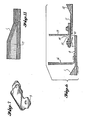
- FIG. 3 it can be seen that lightning protection shielding layers on aircraft structural member 1, e.g. the forward fairing, make electrical contact from the external face to the internal surface through the permanent structural fasteners.
- the internal surface of structural member 1 makes electrical contact with grounding strip member 2.
- Grounding strip member 2 makes electrical contact with grounding clip member 3 comprising a gap-filling lightning protection clip.
- Grounding clip member 3 can be seen in FIGS. 4 and 5 to comprise a rectangular shaped base portion having two apertures therein for mounting to adjacent aircraft support structure, viz. fan cowl support member 6, the rectangular base support portion extending on one side thereof to provide a tongue-like flexible contact portion for flexed contact against grounding strip member 2.
- grounding strip member 2 and grounding clip member 3 are provided with tungsten carbide coatings respectively 22 and 23. Tungsten carbide coatings 22 and 23 prevent wear and gauling. Gap-filling grounding clip member 3 has a thickness of about 0.016 inches. Grounding strip member 2 and grounding clip member 3 bridge the gap across the joint between structural members 1 and 6 thereby preventing electrical current jumping the gap and causing sparking and electrical current leakage to the inside region. Grounding clip member 3 and member 4 make electrical contact with supporting structural member 7, thereby completing the electrical and lightning protection circuit across the interface. Grounding strip member 2, grounding clip member 3, and member 4 comprise corrosion-resistant steel, viz.
- Member 5 comprising the forward fairing angle
- fan cowl support member 6, and member 7 comprising the fan cowl support skin are fully corrosion-resistant finished to protect against variable atmospheric corrosion elements over the aircraft lifespan.
- the aforementioned members 5, 6, and 7 are made of aluminum alloy material for the light-weight design requirements. Aluminum alloy corrosion occurs unless full corrosion protection is provided against atmospheric conditions to which the aircraft are subjected.
- grounding clip member 3 and grounding clip member 9, respectively are the gap-filling lightning protection clip structures which are configured geometrically to permit them to be utilized on variable contoured surfaces without the requirement of adapting the respective grounding clip members to fit the various contours of the many different aerodynamic geometric shapes in different applications of the present lightning protection electrical circuit path coupling structures.
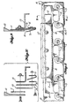
- grounding clip member 9 (corresponding to grounding clip member 3 of FIG. 3) is U-shaped in that the elongated tongue-like portion extending from the base thereof is doubled back on itself with respect the the base portion and is similarly attached by two fasteners as shown in the base portion.
- Grounding clip member 9 performs a similar function as the aforementioned grounding clip member 3 of FIG. 3 in that, in the second embodiment of FIG. 9, grounding clip member 9 abuts grounding strip member 10 as seen in FIGS. 8, 9, and 10.
- grounding strip member 8 makes contact with structural member 1 as did grounding strip member 2 with forward fairing 1 in FIG. 3, grounding strip member 8 of FIG. 6 having a thickness of about 0.005 inches.
- Grounding strip member 8 of FIG. 6 makes electrical contact with U-shaped grounding clip member 9, thereby bridging the gap and providing electrical conductivity through the circuit path across the joint between the aircraft structural members 1 and 12 thus preventing current from jumping the gap and also preventing electrical current leakage to the inside surfaces and structure.
- Grounding clip member 9 of FIG. 6 has a thickness of about 0.016 inches.
- Grounding clip member 9 makes electrical contact with member 10 which comprises the fixed fairing support structure
- member 10 makes electrical contact with member 11 which comprises the fixed fairing panel.
- Member 11 makes electrical contact with member 12 which is the lightning protection layer and thereby providing the requisite electrical circuit path into the interfacing structure, viz. composite, sandwich panel, etc.
- Members 8, 9, 10, and 11 comprise corrosion-resistant steel, viz.
- members 13, 14, 15, and 16 comprise aluminum alloy material for lightweight design, thereby satisfying the minimum weight requirements for fuel economy of the aircraft. Further, members 13, 14, 15, and 16 are fully corrosion-resistant finished to thereby protect against variable atmospheric corrosion over the life span of the aircraft. Aluminum alloy thereby finished as members 13, 14, 15, and 16 do not provide an electrical current path, thereby restricting the electrical current path to the bare corrosion-resistant steel members hereinbefore described, viz. those comprising stainless steel.
- FIGS. 9 and, more particularly, 10 a comparison of, and illustration of the method of integrating coating aluminum structure with bare corrosion-resistant steel, viz. stainless steel, to provide a continuous electrical current path can be readily seen.
- members 8, 9, 10, and 11 are made of corrosion-resistant stainless steel material and provide a continuous bare metal electrical contact path whereas as members 13, 14, 15, and 16, in contrast, are made of aluminum alloy material which is fully corrosion-resistant finished and which does not provide an electrical current path.
- Layers 1 and 17 of the structure shown in FIG. 11 are shielding layers on the internal face side and also on the external face side of the composite sandwich panel or door structure shown.
- Layer 1 in the event of a composite structure constructed of non-metallic composite material, is an aluminum foil layer and, on a graphite composite structure, layer 1 comprises an aluminum foil layer with a fiberglass layer against the graphite.
- Layer 17 on the external face on a non-metallic composite material panel comprises a fiberglass weave coated with aluminum and in a graphite composite panel this same layer 17 requires a layer of non-metallic composite material between it and the graphite surface. (Aluminum corrodes when in contact with graphite and, therefore, the above requirements are necessary on a graphite composite panel.) Suitable coupling between such composite structures is shown in FIG. 6.
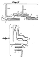
- FIG. 12 is included as a circuit schematic showing current flow path represented by arrows through the lightning protection electrical current path coupling structure shown in FIG. 6 while FIG. 13 is representative of the current path flow through the lightning protection electrical current coupling structure shown in FIG. 3.
- FIG. 12 is included as a circuit schematic showing current flow path represented by arrows through the lightning protection electrical current path coupling structure shown in FIG. 6 while FIG. 13 is representative of the current path flow through the lightning protection electrical current coupling structure shown in FIG. 3.
Landscapes
- Engineering & Computer Science (AREA)
- Aviation & Aerospace Engineering (AREA)
- Elimination Of Static Electricity (AREA)
Claims (3)
Priority Applications (3)
| Application Number | Priority Date | Filing Date | Title |
|---|---|---|---|
| US06/578,396 US4574325A (en) | 1984-02-09 | 1984-02-09 | Lightning protection electrical circuit path for coupling between aircraft structures |
| DE8585201778T DE3578497D1 (de) | 1985-11-01 | 1985-11-01 | Blitzschutzvorrichtung fuer flugzeugbauteile. |
| EP19850201778 EP0221202B1 (de) | 1985-11-01 | 1985-11-01 | Blitzschutzvorrichtung für Flugzeugbauteile |
Applications Claiming Priority (1)
| Application Number | Priority Date | Filing Date | Title |
|---|---|---|---|
| EP19850201778 EP0221202B1 (de) | 1985-11-01 | 1985-11-01 | Blitzschutzvorrichtung für Flugzeugbauteile |
Publications (2)
| Publication Number | Publication Date |
|---|---|
| EP0221202A1 EP0221202A1 (de) | 1987-05-13 |
| EP0221202B1 true EP0221202B1 (de) | 1990-06-27 |
Family
ID=8194076
Family Applications (1)
| Application Number | Title | Priority Date | Filing Date |
|---|---|---|---|
| EP19850201778 Expired EP0221202B1 (de) | 1984-02-09 | 1985-11-01 | Blitzschutzvorrichtung für Flugzeugbauteile |
Country Status (2)
| Country | Link |
|---|---|
| EP (1) | EP0221202B1 (de) |
| DE (1) | DE3578497D1 (de) |
Families Citing this family (3)
| Publication number | Priority date | Publication date | Assignee | Title |
|---|---|---|---|---|
| US9533770B2 (en) | 2011-03-16 | 2017-01-03 | Airbus Operations Limited | Aircraft bonding network |
| US10549865B2 (en) * | 2017-10-19 | 2020-02-04 | Honeywell International Inc. | Lightning protected gas turbine engine |
| CN112510989A (zh) * | 2020-11-17 | 2021-03-16 | 中航通飞华南飞机工业有限公司 | 一种飞机高温区电磁干扰抑制方法及装置 |
Family Cites Families (5)
| Publication number | Priority date | Publication date | Assignee | Title |
|---|---|---|---|---|
| US3166660A (en) * | 1960-05-09 | 1965-01-19 | Square D Co | Contact construction with metallic contact members and auxiliary metallic arc suppressant conducting members |
| US3574570A (en) * | 1968-04-29 | 1971-04-13 | Talon Inc | Composite contact structure for connection to an aluminum support |
| DE7009197U (de) * | 1970-03-13 | 1970-09-10 | Hellige & Co Gmbh F | Masseverbindung fuer mehrere einschuebe von elektronischen geraeten, z.b. von mehrkanal-telemetriegeraeten. |
| DE2235216C3 (de) * | 1972-07-18 | 1975-12-11 | Siemens Ag, 1000 Berlin Und 8000 Muenchen | Anordnung zur Abdichtung von Fugen an Abschirmungen |
| DE3313967A1 (de) * | 1983-04-18 | 1984-10-18 | Siemens AG, 1000 Berlin und 8000 München | Vorrichtung zum sicheren herstellen von elektrisch leitenden verbindungen zwischen gehaeuseteilen eines gehaeuses |
-
1985
- 1985-11-01 DE DE8585201778T patent/DE3578497D1/de not_active Expired - Lifetime
- 1985-11-01 EP EP19850201778 patent/EP0221202B1/de not_active Expired
Also Published As
| Publication number | Publication date |
|---|---|
| DE3578497D1 (de) | 1990-08-02 |
| EP0221202A1 (de) | 1987-05-13 |
Similar Documents
| Publication | Publication Date | Title |
|---|---|---|
| US4574325A (en) | Lightning protection electrical circuit path for coupling between aircraft structures | |
| US3989984A (en) | Aircraft lightning protection means | |
| EP0371905B1 (de) | Überleitungsmittel für die kontinuierliche elektrische Leitung bei Faserverbundverbindungen | |
| US4352142A (en) | Composite aircraft structure having lightning protection | |
| US7554785B2 (en) | Lightning damage protection for composite aircraft | |
| US5698316A (en) | Apparatus and methods of providing corrosion resistant conductive path across non conductive joints or gaps | |
| US5524846A (en) | Fire protection system for airplanes | |
| US3416027A (en) | Radome lightning protection means | |
| US6086975A (en) | Lighting protection for electrically conductive or insulating skin and core for honeycomb structure | |
| AU688140B2 (en) | Lightweight braided shielding for wiring harnesses | |
| EP1628879B1 (de) | Verbundstruktur-blitzschlagschutz | |
| US7236343B2 (en) | Method and system for lightning current conduction protection using foil bonded strips | |
| EP0278611A1 (de) | Kombinierte Sammelschiene und elektrische Verbindung | |
| EP0217312A3 (de) | Blitzschutzeinrichtung für Verbundwerkstoffe im Flugzeugaufbau | |
| EP0221202B1 (de) | Blitzschutzvorrichtung für Flugzeugbauteile | |
| JPS63247199A (ja) | 複合外板材の重なり合うセクションを静電放電から保護する方法 | |
| EP3250459B1 (de) | Leitendes dichtungselement | |
| EP3929040B1 (de) | Blitzschutz für eine scheibenwischeranlage eines flugzeuges | |
| EP0227122B1 (de) | Blitzschutzgerät für eine äussere Oberfläche | |
| ATE37501T1 (de) | Blitzschutzmaterial. | |
| US6498292B2 (en) | Conductive coating arrangement | |
| EP0089953B1 (de) | Befestigungsvorrichtung und verfahren für kompositstrukturen | |
| Taylor | Design and construction of electronic systems for military environments | |
| DISCIJS8OM'NANE et al. | J~ AUTHORIS MELY | |
| Jackson | Multiwall thermal protection system |
Legal Events
| Date | Code | Title | Description |
|---|---|---|---|
| PUAI | Public reference made under article 153(3) epc to a published international application that has entered the european phase |
Free format text: ORIGINAL CODE: 0009012 |
|
| AK | Designated contracting states |
Kind code of ref document: A1 Designated state(s): DE FR GB IT NL |
|
| 17P | Request for examination filed |
Effective date: 19870526 |
|
| 17Q | First examination report despatched |
Effective date: 19890308 |
|
| GRAA | (expected) grant |
Free format text: ORIGINAL CODE: 0009210 |
|
| ITF | It: translation for a ep patent filed | ||
| AK | Designated contracting states |
Kind code of ref document: B1 Designated state(s): DE FR GB IT NL |
|
| REF | Corresponds to: |
Ref document number: 3578497 Country of ref document: DE Date of ref document: 19900802 |
|
| ET | Fr: translation filed | ||
| PLBE | No opposition filed within time limit |
Free format text: ORIGINAL CODE: 0009261 |
|
| STAA | Information on the status of an ep patent application or granted ep patent |
Free format text: STATUS: NO OPPOSITION FILED WITHIN TIME LIMIT |
|
| 26N | No opposition filed | ||
| ITTA | It: last paid annual fee | ||
| PGFP | Annual fee paid to national office [announced via postgrant information from national office to epo] |
Ref country code: GB Payment date: 19931101 Year of fee payment: 9 |
|
| PGFP | Annual fee paid to national office [announced via postgrant information from national office to epo] |
Ref country code: FR Payment date: 19931129 Year of fee payment: 9 |
|
| PGFP | Annual fee paid to national office [announced via postgrant information from national office to epo] |
Ref country code: NL Payment date: 19931130 Year of fee payment: 9 Ref country code: DE Payment date: 19931130 Year of fee payment: 9 |
|
| PG25 | Lapsed in a contracting state [announced via postgrant information from national office to epo] |
Ref country code: GB Effective date: 19941101 |
|
| PG25 | Lapsed in a contracting state [announced via postgrant information from national office to epo] |
Ref country code: NL Effective date: 19950601 |
|
| GBPC | Gb: european patent ceased through non-payment of renewal fee |
Effective date: 19941101 |
|
| NLV4 | Nl: lapsed or anulled due to non-payment of the annual fee | ||
| PG25 | Lapsed in a contracting state [announced via postgrant information from national office to epo] |
Ref country code: FR Effective date: 19950731 |
|
| PG25 | Lapsed in a contracting state [announced via postgrant information from national office to epo] |
Ref country code: DE Effective date: 19950801 |
|
| REG | Reference to a national code |
Ref country code: FR Ref legal event code: ST |