EP0221241B1 - Toit ouvrant pour véhicules automobiles - Google Patents
Toit ouvrant pour véhicules automobiles Download PDFInfo
- Publication number
- EP0221241B1 EP0221241B1 EP19860109516 EP86109516A EP0221241B1 EP 0221241 B1 EP0221241 B1 EP 0221241B1 EP 19860109516 EP19860109516 EP 19860109516 EP 86109516 A EP86109516 A EP 86109516A EP 0221241 B1 EP0221241 B1 EP 0221241B1
- Authority
- EP
- European Patent Office
- Prior art keywords
- guide
- cover
- pin
- sliding
- region
- Prior art date
- Legal status (The legal status is an assumption and is not a legal conclusion. Google has not performed a legal analysis and makes no representation as to the accuracy of the status listed.)
- Expired - Lifetime
Links
- 239000012780 transparent material Substances 0.000 claims description 5
- 230000002093 peripheral effect Effects 0.000 claims 1
- 238000006073 displacement reaction Methods 0.000 description 9
- XLYOFNOQVPJJNP-UHFFFAOYSA-N water Substances O XLYOFNOQVPJJNP-UHFFFAOYSA-N 0.000 description 7
- 239000004033 plastic Substances 0.000 description 5
- 239000000463 material Substances 0.000 description 4
- 238000007789 sealing Methods 0.000 description 3
- 230000000694 effects Effects 0.000 description 2
- 238000004519 manufacturing process Methods 0.000 description 2
- 238000009423 ventilation Methods 0.000 description 2
- 238000013459 approach Methods 0.000 description 1
- 230000015572 biosynthetic process Effects 0.000 description 1
- 230000006835 compression Effects 0.000 description 1
- 238000007906 compression Methods 0.000 description 1
- 238000010276 construction Methods 0.000 description 1
- 238000010304 firing Methods 0.000 description 1
- 238000005187 foaming Methods 0.000 description 1
- 230000003993 interaction Effects 0.000 description 1
- 230000007257 malfunction Effects 0.000 description 1
- 239000002984 plastic foam Substances 0.000 description 1
- 108090000623 proteins and genes Proteins 0.000 description 1
- 230000000284 resting effect Effects 0.000 description 1
- IHQKEDIOMGYHEB-UHFFFAOYSA-M sodium dimethylarsinate Chemical class [Na+].C[As](C)([O-])=O IHQKEDIOMGYHEB-UHFFFAOYSA-M 0.000 description 1
- 230000007704 transition Effects 0.000 description 1
Images


Classifications
-
- B—PERFORMING OPERATIONS; TRANSPORTING
- B60—VEHICLES IN GENERAL
- B60J—WINDOWS, WINDSCREENS, NON-FIXED ROOFS, DOORS, OR SIMILAR DEVICES FOR VEHICLES; REMOVABLE EXTERNAL PROTECTIVE COVERINGS SPECIALLY ADAPTED FOR VEHICLES
- B60J7/00—Non-fixed roofs; Roofs with movable panels, e.g. rotary sunroofs
- B60J7/0007—Non-fixed roofs; Roofs with movable panels, e.g. rotary sunroofs moveable head-liners, screens, curtains or blinds for ceilings
- B60J7/003—Non-fixed roofs; Roofs with movable panels, e.g. rotary sunroofs moveable head-liners, screens, curtains or blinds for ceilings one or more sliding rigid plate or lammellae
-
- B—PERFORMING OPERATIONS; TRANSPORTING
- B60—VEHICLES IN GENERAL
- B60J—WINDOWS, WINDSCREENS, NON-FIXED ROOFS, DOORS, OR SIMILAR DEVICES FOR VEHICLES; REMOVABLE EXTERNAL PROTECTIVE COVERINGS SPECIALLY ADAPTED FOR VEHICLES
- B60J7/00—Non-fixed roofs; Roofs with movable panels, e.g. rotary sunroofs
- B60J7/02—Non-fixed roofs; Roofs with movable panels, e.g. rotary sunroofs of sliding type, e.g. comprising guide shoes
- B60J7/04—Non-fixed roofs; Roofs with movable panels, e.g. rotary sunroofs of sliding type, e.g. comprising guide shoes with rigid plate-like element or elements, e.g. open roofs with harmonica-type folding rigid panels
- B60J7/043—Sunroofs e.g. sliding above the roof
- B60J7/0435—Sunroofs e.g. sliding above the roof pivoting upwardly to vent mode and moving at the outside of the roof to fully open mode
-
- B—PERFORMING OPERATIONS; TRANSPORTING
- B60—VEHICLES IN GENERAL
- B60J—WINDOWS, WINDSCREENS, NON-FIXED ROOFS, DOORS, OR SIMILAR DEVICES FOR VEHICLES; REMOVABLE EXTERNAL PROTECTIVE COVERINGS SPECIALLY ADAPTED FOR VEHICLES
- B60J7/00—Non-fixed roofs; Roofs with movable panels, e.g. rotary sunroofs
- B60J7/02—Non-fixed roofs; Roofs with movable panels, e.g. rotary sunroofs of sliding type, e.g. comprising guide shoes
- B60J7/04—Non-fixed roofs; Roofs with movable panels, e.g. rotary sunroofs of sliding type, e.g. comprising guide shoes with rigid plate-like element or elements, e.g. open roofs with harmonica-type folding rigid panels
- B60J7/057—Driving or actuating arrangements e.g. manually operated levers or knobs
-
- B—PERFORMING OPERATIONS; TRANSPORTING
- B60—VEHICLES IN GENERAL
- B60J—WINDOWS, WINDSCREENS, NON-FIXED ROOFS, DOORS, OR SIMILAR DEVICES FOR VEHICLES; REMOVABLE EXTERNAL PROTECTIVE COVERINGS SPECIALLY ADAPTED FOR VEHICLES
- B60J7/00—Non-fixed roofs; Roofs with movable panels, e.g. rotary sunroofs
- B60J7/185—Locking arrangements
- B60J7/19—Locking arrangements for rigid panels
Definitions
- the invention relates to a sunroof of the type mentioned in the preamble of claim 1 and resulting from DE-A 32 11 519.
- two lateral guide grooves are formed on the frame, in each of which a guide slide articulated on the front edge of the cover is guided so as to be longitudinally displaceable via a threaded cable.
- a push rod is articulated on each guide carriage, which carries a bearing journal on its rear end section, which in turn slides in an elongated hole in each case by a pivot lever which is articulated on the sunroof frame.
- This carries on its cover-side end section a guide pin which is rotatably and longitudinally mounted in a backdrop of two guide rails attached to the underside of the cover.
- a sliding roof is disclosed in DE-A 32 27 800, at the front, outer edge regions of which two levers, which intersect in the central region of their longitudinal extension, are each articulated, each of which slides with its lower end sections in guide grooves provided in the sliding roof frame.
- the cover hinged to the upper ends of the levers is longitudinally displaceable; the lid is in its extreme open position above the rigid roof area at the back and runs approximately horizontally. Since the cover lies relatively far above the outer skin of the roof, it causes increased air resistance. Since the cover also protrudes far backwards, it is stimulated to vibrate in an unpleasant manner, especially at higher vehicle speeds.
- the levers used to pivot the lid are relatively complicated and therefore expensive to manufacture.
- the object of the invention is therefore to design a sunroof of the type mentioned in the preamble of claim 1 such that the pivoting lever is pivoted backwards when the cover is moved into its open position by a simply designed, inexpensive to manufacture and light-weight device.
- the pivoting lever is pivoted up by merely moving the cover and then pivoted backwards as far as possible by the guide pin rotating in the circular recess until its flattening is in alignment with the long sides of the backdrop. In this swivel position of the swivel lever, the cover can finally be moved further backwards.
- the circular recess arranged in the setting for receiving the guide pin can be provided very inexpensively.
- the device essentially consisting of these features for pivoting the pivoting lever is light in weight and is very robust and less susceptible to malfunction during operation. If worn, the guide pin can also be replaced very easily.
- a lid which is articulated according to the features of claims 3 to 5 on two pivot levers and, in addition, from each of which protrudes into the link of the guide rails engaging support pin (feature of claim 5) is held so optimally that it itself extreme open position hardly vibrates.
- the cover is kept optimally vibration-free (feature of patent claim 6).
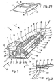
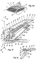
- the sunroof 1 shown in Figures 1 to 15 is constructed symmetrically with respect to its longitudinal central axis, which is why only the parts of the sunroof 1 on the right in the direction of travel of the passenger car are explained below; however, these are present in pairs on this.
- a passenger car equipped with the sunroof 1 (FIGS. 2a, 4a, 6a, 9a, 11a, 13a, 13b) has a sunroof frame 3 surrounding the roof cutout 2, which according to FIGS. 1, 2, 4, 6, 9, 11, 13 and 15 consists of a circumferential vertical leg 3 'and an approximately horizontally inwardly projecting support flange 3 ".
- a circumferential water gutter 4 is formed on the upper region of the vertical leg 3' of the sliding roof frame 3, which has an open top , U-shaped cross-sectional profile.
- the lateral support flanges 3 ′′ provided on both sides of the longitudinal center plane of the passenger car are each provided with an elongated receiving element 5.
- FIG. 1 At right angles from the screw-on flange 5 'of the receiving element 5 there extends a guide part 7 which extends over its entire length and which lies in the region of the vertical leg 3' of the sunroof frame 3.
- the guide part 7 has on its inner side facing the longitudinal plane of the vehicle a guide groove 8 running almost over its entire length.
- This is rectangular and consists of three continuously extending longitudinal sections 8 ', 8 “, 8'", the front, first longitudinal section 8 ' an angle of approximately 30 ° and the adjoining second longitudinal section 8 ′′ forms an angle of approximately 5 ° with the lower edge 7 ′ of the guide part 7; the third longitudinal section 8 ′ ′′ runs approximately parallel to the lower edge 7 ′.
- the transition point from the second longitudinal section 8 "to the third longitudinal section 8 '" lies approximately in the longitudinal central region of the guide groove 8.
- the second and third longitudinal sections 8 "and 8'" also run straight or strongly curved; this allows the cover 6 in an optimal manner above the rigid rear roof rich 2 'or the headlining 44, 44' between the outer roof skin and the inner lining.
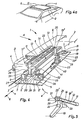
- the cover 6 provided on the sunroof 1, which is shown in FIGS. 1 to 10, has on its underside a covering (not shown), which is expediently formed by plastic foam or the like. Furthermore, an angle profile 10 is attached to the underside of the cover 6 in the region of its opposite, lateral longitudinal edges, on the vertical leg of which a guide rail 11 with a rectangular cross-sectional profile running parallel to the guide part 7 is fastened by a number of screws.
- the guide rails 11 each have a rectangular-shaped link 12 on their mutually facing broad sides. This is open to the vehicle center plane and extends from the rear end of the guide rail 11 to its front area.
- a circular recess 13 is formed, the diameter of which is greater than the width of the link 12.
- the circular recess 13 is arranged symmetrically to the longitudinal extension of the link 12 in all the drawings of the exemplary embodiment; however, it can also be provided asymmetrically with respect to this, ie tangential to an upper or lower wall of the link 12.
- each receiving element 5 a pivot lever bearing 17 is fastened to its screw-on flange 5 ', to which a pivot lever 19 is articulated via a bearing pin 18.
- This has an angled section 19 'on its cover-side end region such that when the cover 6 is located in the extreme open position IV (FIG. 9), it lies with the rear roof region 2' underneath it in approximately a reference plane and close to it.
- This can be achieved by a corresponding arrangement of the guide grooves 8 in the guide parts 7.
- a guide pin 20 is inserted in a rotationally fixed manner at the free end region of the angled end section 19 'of each pivot lever 19.
- the guide pin 20 has two symmetrically arranged flats 21 which lie opposite the genes.
- a slide piece 20 ' is formed on the guide pin 20, which slidably engages in the link 12 of the guide rails 11, so that the latter and thus the cover 6 relative to the guide pin 20 are movable. As shown in FIG. 9 and in particular FIG.
- the flats 21 are each arranged on the guide pin 20 (or these are inserted into the pivot lever 19 in a rotationally fixed manner) such that when the pivot lever 19 is pivoted into the rear end position - in which it overlaps an angular recess 19 "is supported on the inner leg 4 'of the rear section of the water gutter 4 - lie approximately in a reference plane to the rigid rear roof area 2' underneath.
- the guide pin 20 with its cylindrical outer jacket is in of the circular recess 13 (FIGS. 3, 5, 7, 12, 14).
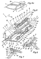
- a support pin 22 protrudes from the angular range of each pivot lever 19 and runs parallel to the guide pin 20 and points in the same direction as this its center distance from the guide pin 20 corresponds to the distance from the center of the circular igen recess 13 to the center of the width of the opening 14. Furthermore, the diameter of the support pin 22 is dimensioned such that it can be guided through the opening 14 and that the guide rail 11 with the support pin 22 located in its setting 12 relative to this with formation a sliding guide is longitudinally displaceable. In the closed position I of the cover 6 (FIG.
- the pivot levers 19 are each provided with a receiving pin 23, which is located opposite the support pin 22 and extends coaxially therewith.
- a guide slide 26 is provided which is articulated to the guide rail 11 and which has a U-shaped cross-sectional profile with a long leg 26 'and a short leg 26 ", as can be seen in particular in FIGS. 1 and 2.
- a longitudinal groove with a U-shaped cross section is formed on the inside of the short leg 26 ", which is assigned to the guide rib 9 on the guide part 7, as a result of which the guide carriage 26 can be displaced along this in a positively guided manner.
- a tension and compression-resistant drive cable 27 attached, in which a rotating, not shown drive pinion engages in a known manner.
- the long leg 26 'of the guide carriage 26 runs along the inner, vertical wall of the guide part 7 and has at its front end region a receiving bore 28 in which a hinge pin 29 is rotatably mounted.
- This has an end section running towards the short leg 26 ′′, which expediently engages in the guide groove 8 of the guide part 7 via a plastic roller 29 ′, while the opposite end section of the hinge pin 29 is rotatably or rotatably received by a bore in a hinge plate 30 29 projects so far beyond the articulated bracket 30 that a toothed rack 31 can be pressed onto its free end section via an overlying receiving bore 31 '.
- Adjacent to this is a further receiving bore 31 "into which a link pin 32 is inserted in a rotationally fixed manner its opposite end section is rotatably inserted into a receiving bore 28 'of the long leg 26' and projects so far beyond it that its free end section expediently engages in the guide groove 8 via a plastic roller.
- the slide pin 33 in the firing position I of the cover 6, the slide pin 33 is located near the deepest point of the first longitudinal section 8 'of the guide groove 8, while the hinge pin 29 is located directly at the front end region of the second longitudinal section 8 "; likewise in this, adjacent to the hinge pin 29, there is also the link pin 32.
- the toothed rack 31 projecting from each guide slide 26 meshes with a toothed segment 35, which is rotatably supported with its bearing bore on a bearing part 36 fastened to the screw-on flange 5 'of the receiving element 5.
- a screw-on bracket 37 is also fastened on the screw-on flange 5 ', from which a bearing pin 38, which extends axially parallel to the mounting pin 23 of the pivot lever 19, projects.
- a securing fork 39 with an outwardly open jaw opening 39 'and an articulated extension approximately opposite this is pivotably mounted on this.
- a push rod 40 pivotably mounted on this is articulated with its opposite end section on the toothed segment 35.
- a tension spring 41 is attached to the screw-on angle 37 and engages with its opposite end on an angled portion of the push rod 40.
- the tension spring 41 engages the push rod 40 with prestress and relaxes continuously during the opening movements of the cover 6; thus the tension spring 41 acts as a support when the toothed segment 35 is pivoted in the direction of the arrow e.
- the securing fork 39 overlaps the receiving pin 23 protruding from the pivoting lever 19 in such a way that its mouth opening 39 'points towards the rear.
- the rear region of the cover 6 is thus secured in the closed position I against violent, upward opening.
- the securing fork 39 acting on the receiving pin 23 also acts as a support when moving the cover 6 from its closed position I (FIG. 2) to its open position 11 (FIG. 4). Since in this case the toothed rack 31 attached to the guide slide 26 meshes with the toothed segment 35, this is pivoted in the direction of arrow e and in turn thereby swivels the securing fork 39 upward via the push rod 40 (FIG. 4).
- a headliner made of flexible material can be provided, which is usually biased in the area of the rear end of the cover 6 and below the vehicle roof to a spring force Roll can be wound up.
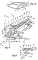
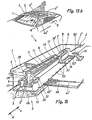
- the sunroof 1 shown in FIGS. 11 to 15 has, apart from parts 31 and 35 to 41, all the parts which also have the sunroof 1 shown in FIGS. 1 to 10. Therefore, only the parts added to these are mentioned in the description of FIGS. 11 to 15 below.
- the Lid 6 is not foamed with plastic on its underside.
- the headliner 44 which is made of rigid material in this sliding roof 1, runs with its side edges along the inner edge of the screw-on flange 5 'of the receiving element 5 and in the area of an inner lining 48.
- an articulated connecting tab 45 attached is attached at its opposite end to the hinge bracket 30.
- an upwardly protruding bracket 46 is attached to the rear side areas of the headliner 44, which has an inclined upward and forward receiving slot 47; this is open to the front and, if necessary, can also be curved. In its closed position shown in FIG.
- the headliner 44 bears against the mounting pin 23 of the pivot lever 19 via the holding bracket 46. Since the headliner 44 is connected to the guide carriage 26 via the articulated connecting straps 45, it is moved longitudinally when the cover 6 is moved from the closed position I to the extreme open position IV and is thereby shifted into the area between the outer skin of the roof and the inner lining.
- the receiving slot 47 of the bracket 46 cooperates with the receiving pin 23 of the pivot lever 19 such that it is released when pivoting the latter (arrow direction f).
- the roof lining 44 'made of rigid, opaque material is guided in a longitudinally displaceable manner on its two lateral edge regions by an inner lining 48 attached to the underside of the supporting flange 3 "of the sunroof frame 3.
- the roof lining 44' carries a manually operable locking device on its top 49, the bolt 49 'of which engages spring-loaded into a number of recesses 50 formed in the screw-on flange 5'.
- an upwardly protruding holding bracket 51 is attached to the headliner 44 'on both of its rear side areas, on which a support arm running obliquely forwards and upwards 52, through which a receiving opening 52 'is formed which is open towards the front.
- the inside of the support arm 52 can also be curved in accordance with the circular arc movement of the receiving pin 23.
- the support arm 52 covers the receptacle projecting from the pivot lever 19 Ahmezapfen 23, so that the cover 6 is secured with against unauthorized, upward opening.
- the headliner 44 ' is pushed backwards by at least one latching position (FIG. 15)
- the receiving pin 23 is released in the exemplary embodiment and the cover 6 can thereby be shifted to its extreme open position IV in the usual way.
- the cover 6 consists at least in its central region, if necessary also completely from transparent material 6 '. If the headliner 44 'is in its foremost latching position (FIG. 13), no light can penetrate into the vehicle interior via the cover 6 (FIG. 13a). However, if the headliner 44 'is shifted backwards by at least a few latching positions (FIG. 15), light can enter the vehicle interior via the transparent material 6' of the cover 6 (FIG. 13b).
- the cover 6 can be provided with a circumferential seal, not shown, which is expediently plugged onto the flange projecting downwards and has a sealing lip which projects laterally. In the closed position I of the cover 6, this can rest on the outer skin of the roof with a prestress. Such a sealing lip advantageously has a high sealing effect against water ingress.
- a second hose seal can be placed on the inner leg 4 'of the water gutter 4.
- the sliding pin 33 slides over the obliquely upward longitudinal section 8 ′ of the guide groove 8 and thereby lifts the front edge of the cover 6 upwards via the push arm 11 ′.
- the rack 31 meshes with the toothed segment 35 at the same time, the latter is pivoted in the direction of arrow e and, as a result, the securing fork 39, which engages over the locating pin 23 in the closed position I of the cover 6, is pivoted upward to release it.
- the guide rail 11 is pivoted about the circular recess 13 provided at the rear end of its link 12 around the guide pin 20 of the pivoting lever 19, as a result of which this is moved in the direction of arrow f (by further longitudinal displacement of the guide carriage 26 in the direction of arrow c ) is swung up to its culmination point; the cover 6 is also shifted upwards at the same time. If the pivot lever 19 is pivoted beyond its culmination point in the direction of the arrow f (by further longitudinal displacement of the guide) tion slide 26 in the direction of arrow c), the support pin 22 projecting from the pivot lever 19 approaches the opening 14 provided on the link 12 (illustrated in FIG. 7 with arrow direction a) and finally engages in this (FIG.
- the drive cable 27 is moved lengthwise in the direction of the arrow d by the corresponding direction of rotation of the drive pinion, which of course also displaces the guide carriage 26 in this direction.
- the cover 6 slides along the link 12 via the slide 20 'and the support pin 22 to the front in the direction of the arrow d until the guide pin 20 is located in the circular recess 13.
- the cover 6 of the sunroof 1 shown in FIGS. 11 to 15 is shifted from its closed position I into its extreme open position IV in a completely analogous manner to that set out above. Therefore, in the following, only the roof lining 44 or 44 'is referred to when the cover 6 is moved. If the sunroof 1 shown in FIGS. 11 and 11a is moved from its closed position I to its extreme open position IV as explained, the roof lining 44 is displaced via the articulated connecting tab 45 into an intermediate space between the outer roof skin and the inner lining. Since the bracket 46 is also shifted backwards, the receiving pin 23 on the pivot lever 19 is released for pivoting it up (arrow direction f).
Landscapes
- Engineering & Computer Science (AREA)
- Mechanical Engineering (AREA)
- Body Structure For Vehicles (AREA)
- Seal Device For Vehicle (AREA)
Claims (12)
Applications Claiming Priority (2)
| Application Number | Priority Date | Filing Date | Title |
|---|---|---|---|
| DE19853536184 DE3536184C1 (de) | 1985-10-10 | 1985-10-10 | Schiebedach fuer ein Kraftfahrzeug,insbesondere Personenkraftwagen |
| DE3536184 | 1985-10-10 |
Publications (3)
| Publication Number | Publication Date |
|---|---|
| EP0221241A2 EP0221241A2 (fr) | 1987-05-13 |
| EP0221241A3 EP0221241A3 (en) | 1988-11-17 |
| EP0221241B1 true EP0221241B1 (fr) | 1990-02-07 |
Family
ID=6283274
Family Applications (1)
| Application Number | Title | Priority Date | Filing Date |
|---|---|---|---|
| EP19860109516 Expired - Lifetime EP0221241B1 (fr) | 1985-10-10 | 1986-07-11 | Toit ouvrant pour véhicules automobiles |
Country Status (2)
| Country | Link |
|---|---|
| EP (1) | EP0221241B1 (fr) |
| DE (1) | DE3536184C1 (fr) |
Families Citing this family (20)
| Publication number | Priority date | Publication date | Assignee | Title |
|---|---|---|---|---|
| US5114208A (en) * | 1989-08-04 | 1992-05-19 | Aisin Seiki Kabushiki Kaisha | Sliding mechanism for sunroof |
| JP2597524Y2 (ja) * | 1990-07-10 | 1999-07-05 | アイシン精機株式会社 | サンルーフ装置 |
| FR2677585B1 (fr) * | 1991-06-13 | 1993-10-22 | Heuliez Webasto | Dispositif d'ouverture et de fermeture de toit comprenant un panneau coulissant, notamment pour vehicule automobile. |
| NL194541C (nl) * | 1991-08-29 | 2002-07-02 | Vermeulen Hollandia Octrooien | Werkwijze voor het scharnierbaar met elkaar verbinden van een metalen en kunststof onderdeel, in het bijzonder een open-dakconstructie voor een voertuig, alsmede een scharnierconstructie vervaardigd volgens die werkwijze. |
| NL9101707A (nl) * | 1991-10-14 | 1993-05-03 | Vermeulen Hollandia Octrooien | Open-dakconstructie voor een voertuig. |
| DE9302762U1 (de) * | 1993-02-25 | 1993-04-15 | Kelm, Eckehart, 8031 Gilching | Verstelleinrichtung für ein Hebeschiebedach |
| FR2904793B1 (fr) * | 2006-08-08 | 2011-03-18 | Peugeot Citroen Automobiles Sa | Dispositif de deplacement d'elements de couverture d'un habitacle d'un vehicule automobile et vehicule automobile comportant un tel dispositif |
| DE102013014357B4 (de) * | 2013-08-27 | 2019-05-23 | Audi Ag | Kulissenführungsvorrichtung für ein Dachelement eines öffnungsfähigen Dachsystems eines Fahrzeugs |
| CN108248351A (zh) * | 2016-12-29 | 2018-07-06 | 上海毓恬冠佳汽车零部件有限公司 | 汽车天窗导向联动装置 |
| GB2560733A (en) * | 2017-03-22 | 2018-09-26 | Lewmar Ltd | Sliding roof panel assembly and method for its operation |
| EP3434502B1 (fr) | 2017-07-25 | 2020-09-09 | Inalfa Roof Systems Group B.V. | Structure décapotable pour véhicule |
| CN110997376B (zh) | 2017-08-03 | 2023-02-17 | 英纳法天窗系统集团有限公司 | 用于车辆的开放式车顶构造 |
| EP3476632B1 (fr) | 2017-10-31 | 2020-05-27 | Inalfa Roof Systems Group B.V. | Structure décapotable pour véhicule |
| EP3647094B1 (fr) | 2018-11-05 | 2022-10-26 | Inalfa Roof Systems Group B.V. | Système de toit pour véhicule |
| CN112440697B (zh) | 2019-08-27 | 2023-11-24 | 英纳法天窗系统集团有限公司 | 遮阳系统及其部件的制造方法 |
| EP3792091B1 (fr) | 2019-09-10 | 2022-06-15 | Inalfa Roof Systems Group B.V. | Ensemble de toiture pour véhicule et procédé d'assemblage |
| EP4122729A1 (fr) | 2021-07-20 | 2023-01-25 | Inalfa Roof Systems Group B.V. | Système de toiture |
| EP4122730B1 (fr) * | 2021-07-20 | 2025-06-04 | Inalfa Roof Systems Group B.V. | Système de toiture |
| CN114537101B (zh) * | 2021-12-23 | 2023-07-21 | 河南莱茵汽车制造有限公司 | 一种商务车车顶 |
| DE102023123318A1 (de) * | 2023-08-30 | 2025-03-06 | Webasto SE | Anordnung zum Bewegen eines Deckels für ein Fahrzeugdach, Führungsschiene sowie Fahrzeugdach |
Family Cites Families (5)
| Publication number | Priority date | Publication date | Assignee | Title |
|---|---|---|---|---|
| US4268996A (en) * | 1978-11-15 | 1981-05-26 | Ford Motor Company | Track for sliding closure |
| NL179196C (nl) * | 1980-06-24 | 1986-08-01 | Vermeulen Hollandia Octrooien | Schuifdak voor een voertuig. |
| JPS5833311U (ja) * | 1981-08-29 | 1983-03-04 | ダイキヨ−・ベバスト株式会社 | 乗物用天井窓 |
| DE3211519A1 (de) * | 1982-03-29 | 1983-10-06 | Weinsberg Karosseriewerke | Schiebedach fuer fahrzeuge |
| DE3444841C2 (de) * | 1984-12-08 | 1986-10-09 | Bayerische Motoren Werke AG, 8000 München | Schiebehebedach |
-
1985
- 1985-10-10 DE DE19853536184 patent/DE3536184C1/de not_active Expired
-
1986
- 1986-07-11 EP EP19860109516 patent/EP0221241B1/fr not_active Expired - Lifetime
Also Published As
| Publication number | Publication date |
|---|---|
| DE3536184C1 (de) | 1986-11-20 |
| EP0221241A3 (en) | 1988-11-17 |
| EP0221241A2 (fr) | 1987-05-13 |
Similar Documents
| Publication | Publication Date | Title |
|---|---|---|
| EP0221241B1 (fr) | Toit ouvrant pour véhicules automobiles | |
| EP0381066B1 (fr) | Toit de véhicule ayant une découpure de toit fermant au moyen d'un couvercle | |
| DE3238454C2 (de) | Schiebedach für Fahrzeuge | |
| DE4227402C1 (de) | Fahrzeugdach | |
| DE3632058C2 (fr) | ||
| DE3910894C2 (de) | Bewegungsmechanismus für einen Deckel eines Fahrzeugdachausschnittes | |
| DE3444593A1 (de) | Absenkvorrichtung fuer die heckscheibe von fahrzeugen | |
| DE3310961A1 (de) | Vorrichtung zur arretierung einer voll geoeffneten schiebetuer eines fahrzeugs | |
| EP1112876A2 (fr) | Dispositif pare-soleil pour une région transparente de toit de véhicule | |
| DE3324032A1 (de) | Schiebedach fuer fahrzeuge | |
| DE2601045A1 (de) | Schiebedachbaugruppe fuer fahrzeuge | |
| DE69127909T2 (de) | Schiebe-Hebe-Dach-Vorrichtung für Kraftfahrzeug | |
| DE60017035T2 (de) | Konstruktion eines öffnungsfähigen Farzeugdaches | |
| DE3807961C2 (fr) | ||
| DE102007019858A1 (de) | Dachfensterrollo mit vorgespannten Gleitern | |
| DE3129900C2 (de) | Hebeschiebedach für Kraftfahrzeuge | |
| DE29921860U1 (de) | Fensterrollo für ein Dreiecksfenster eines Kraftfahrzeugs | |
| EP1493601A2 (fr) | Toit de véhicule | |
| DE4001759C1 (en) | Sun roof for motor vehicles - has lever pivoting at end of sliding guide to actuate roof panel | |
| DE3311428A1 (de) | ? | |
| EP0755815B1 (fr) | Toít pliant pour véhicule | |
| DE19634324A1 (de) | Fahrzeugdach | |
| DE19635145C1 (de) | Fahrzeugdach | |
| DE3311478A1 (de) | Hebeschiebedach | |
| DE69925217T2 (de) | Konstruktion eines öffnungsfähigen Fahrzeugdaches |
Legal Events
| Date | Code | Title | Description |
|---|---|---|---|
| PUAI | Public reference made under article 153(3) epc to a published international application that has entered the european phase |
Free format text: ORIGINAL CODE: 0009012 |
|
| AK | Designated contracting states |
Kind code of ref document: A2 Designated state(s): FR GB IT SE |
|
| PUAL | Search report despatched |
Free format text: ORIGINAL CODE: 0009013 |
|
| AK | Designated contracting states |
Kind code of ref document: A3 Designated state(s): FR GB IT SE |
|
| 17P | Request for examination filed |
Effective date: 19881015 |
|
| 17Q | First examination report despatched |
Effective date: 19890713 |
|
| GRAA | (expected) grant |
Free format text: ORIGINAL CODE: 0009210 |
|
| AK | Designated contracting states |
Kind code of ref document: B1 Designated state(s): FR GB IT SE |
|
| GBT | Gb: translation of ep patent filed (gb section 77(6)(a)/1977) | ||
| ET | Fr: translation filed | ||
| ITF | It: translation for a ep patent filed | ||
| PLBE | No opposition filed within time limit |
Free format text: ORIGINAL CODE: 0009261 |
|
| STAA | Information on the status of an ep patent application or granted ep patent |
Free format text: STATUS: NO OPPOSITION FILED WITHIN TIME LIMIT |
|
| 26N | No opposition filed | ||
| ITTA | It: last paid annual fee | ||
| PGFP | Annual fee paid to national office [announced via postgrant information from national office to epo] |
Ref country code: SE Payment date: 19920706 Year of fee payment: 7 |
|
| PGFP | Annual fee paid to national office [announced via postgrant information from national office to epo] |
Ref country code: GB Payment date: 19920710 Year of fee payment: 7 |
|
| PGFP | Annual fee paid to national office [announced via postgrant information from national office to epo] |
Ref country code: FR Payment date: 19920727 Year of fee payment: 7 |
|
| PG25 | Lapsed in a contracting state [announced via postgrant information from national office to epo] |
Ref country code: GB Effective date: 19930711 |
|
| PG25 | Lapsed in a contracting state [announced via postgrant information from national office to epo] |
Ref country code: SE Effective date: 19930712 |
|
| GBPC | Gb: european patent ceased through non-payment of renewal fee |
Effective date: 19930711 |
|
| PG25 | Lapsed in a contracting state [announced via postgrant information from national office to epo] |
Ref country code: FR Effective date: 19940331 |
|
| REG | Reference to a national code |
Ref country code: FR Ref legal event code: ST |
|
| EUG | Se: european patent has lapsed |
Ref document number: 86109516.4 Effective date: 19940210 |
|
| PG25 | Lapsed in a contracting state [announced via postgrant information from national office to epo] |
Ref country code: IT Free format text: LAPSE BECAUSE OF NON-PAYMENT OF DUE FEES;WARNING: LAPSES OF ITALIAN PATENTS WITH EFFECTIVE DATE BEFORE 2007 MAY HAVE OCCURRED AT ANY TIME BEFORE 2007. THE CORRECT EFFECTIVE DATE MAY BE DIFFERENT FROM THE ONE RECORDED. Effective date: 20050711 |