EP0221671A1 - Dehnbare Elektroden zum Aufladen und/oder zum Ablenken von Flüssigkeitströpfchen für Flüssigkeitsstrahl-Markierapparate - Google Patents
Dehnbare Elektroden zum Aufladen und/oder zum Ablenken von Flüssigkeitströpfchen für Flüssigkeitsstrahl-Markierapparate Download PDFInfo
- Publication number
- EP0221671A1 EP0221671A1 EP86307518A EP86307518A EP0221671A1 EP 0221671 A1 EP0221671 A1 EP 0221671A1 EP 86307518 A EP86307518 A EP 86307518A EP 86307518 A EP86307518 A EP 86307518A EP 0221671 A1 EP0221671 A1 EP 0221671A1
- Authority
- EP
- European Patent Office
- Prior art keywords
- electrode
- electrode member
- mounting
- pair
- arm
- Prior art date
- Legal status (The legal status is an assumption and is not a legal conclusion. Google has not performed a legal analysis and makes no representation as to the accuracy of the status listed.)
- Withdrawn
Links
- 239000012530 fluid Substances 0.000 title claims abstract description 41
- 230000003247 decreasing effect Effects 0.000 claims abstract description 13
- 238000007600 charging Methods 0.000 claims description 16
- 230000004323 axial length Effects 0.000 claims description 6
- 230000008878 coupling Effects 0.000 claims 2
- 238000010168 coupling process Methods 0.000 claims 2
- 238000005859 coupling reaction Methods 0.000 claims 2
- 239000000758 substrate Substances 0.000 description 13
- 230000006835 compression Effects 0.000 description 7
- 238000007906 compression Methods 0.000 description 7
- 239000004753 textile Substances 0.000 description 5
- 230000000712 assembly Effects 0.000 description 4
- 238000000429 assembly Methods 0.000 description 4
- 238000006073 displacement reaction Methods 0.000 description 4
- 230000000694 effects Effects 0.000 description 3
- 230000015572 biosynthetic process Effects 0.000 description 2
- 238000004040 coloring Methods 0.000 description 2
- 235000009508 confectionery Nutrition 0.000 description 2
- 230000004048 modification Effects 0.000 description 2
- 238000012986 modification Methods 0.000 description 2
- 239000007787 solid Substances 0.000 description 2
- 239000004677 Nylon Substances 0.000 description 1
- 241000921283 Sutera Species 0.000 description 1
- XMQFTWRPUQYINF-UHFFFAOYSA-N bensulfuron-methyl Chemical compound COC(=O)C1=CC=CC=C1CS(=O)(=O)NC(=O)NC1=NC(OC)=CC(OC)=N1 XMQFTWRPUQYINF-UHFFFAOYSA-N 0.000 description 1
- 239000004020 conductor Substances 0.000 description 1
- 238000013016 damping Methods 0.000 description 1
- 239000012777 electrically insulating material Substances 0.000 description 1
- 238000007786 electrostatic charging Methods 0.000 description 1
- 230000005686 electrostatic field Effects 0.000 description 1
- 238000005421 electrostatic potential Methods 0.000 description 1
- 230000006698 induction Effects 0.000 description 1
- 239000000463 material Substances 0.000 description 1
- 230000007246 mechanism Effects 0.000 description 1
- 239000002184 metal Substances 0.000 description 1
- 238000000034 method Methods 0.000 description 1
- 229920001778 nylon Polymers 0.000 description 1
- 230000000737 periodic effect Effects 0.000 description 1
- 230000004044 response Effects 0.000 description 1
- 238000004904 shortening Methods 0.000 description 1
- 229910001220 stainless steel Inorganic materials 0.000 description 1
- 239000010935 stainless steel Substances 0.000 description 1
- 238000009736 wetting Methods 0.000 description 1
Images

Classifications
-
- B—PERFORMING OPERATIONS; TRANSPORTING
- B41—PRINTING; LINING MACHINES; TYPEWRITERS; STAMPS
- B41J—TYPEWRITERS; SELECTIVE PRINTING MECHANISMS, i.e. MECHANISMS PRINTING OTHERWISE THAN FROM A FORME; CORRECTION OF TYPOGRAPHICAL ERRORS
- B41J2/00—Typewriters or selective printing mechanisms characterised by the printing or marking process for which they are designed
- B41J2/005—Typewriters or selective printing mechanisms characterised by the printing or marking process for which they are designed characterised by bringing liquid or particles selectively into contact with a printing material
- B41J2/01—Ink jet
- B41J2/07—Ink jet characterised by jet control
- B41J2/075—Ink jet characterised by jet control for many-valued deflection
- B41J2/08—Ink jet characterised by jet control for many-valued deflection charge-control type
- B41J2/085—Charge means, e.g. electrodes
-
- B—PERFORMING OPERATIONS; TRANSPORTING
- B41—PRINTING; LINING MACHINES; TYPEWRITERS; STAMPS
- B41J—TYPEWRITERS; SELECTIVE PRINTING MECHANISMS, i.e. MECHANISMS PRINTING OTHERWISE THAN FROM A FORME; CORRECTION OF TYPOGRAPHICAL ERRORS
- B41J2/00—Typewriters or selective printing mechanisms characterised by the printing or marking process for which they are designed
- B41J2/005—Typewriters or selective printing mechanisms characterised by the printing or marking process for which they are designed characterised by bringing liquid or particles selectively into contact with a printing material
- B41J2/01—Ink jet
- B41J2/07—Ink jet characterised by jet control
- B41J2/075—Ink jet characterised by jet control for many-valued deflection
- B41J2/08—Ink jet characterised by jet control for many-valued deflection charge-control type
- B41J2/09—Deflection means
Definitions
- the present invention relates to the field of non-contact fluid marking devices which are commonly known as “ink-jet” or “fluid-jet” marking apparatus. More particularly, the present invention is directed to novel electrodes useful for charging and/or deflecting selected drops in a stream of droplets so as to selectively control the charging and/or deflection, respectively, of the droplets to effect marking upon a substrate.
- Fluid-jet devices in and of themselves are well known through e.g. U.S. Patent Nos. 3,373,437 to Sweet et al, 3,560,988 to Krick; 3,579,721 to Kaltenbach; and 3,596,275 to Sweet.
- prior art fluid-jet devices provide a linear array of fluid-jet orifices formed in an orifice plate from which filaments or streams of pressurized marking fluid (e.g. ink, dye, etc.) are caused to issue from a fluid supply chamber.
- Individually controllable electrostatic charging electrodes are disposed downstream of the orifice plate along the so-called "drop-formation" zone.
- each fluid filament is caused to assume an electrical potential opposite in polarity and related in magnitude to the electrical potential of its respective charging electrode.
- this induced electrostatic potential is then trapped on and in the droplet in the form of an electrical charge.
- Uncharged droplets on the other hand proceed along the normal droplet flight path and are eventually deposited upon a recording substrate.
- the electrode structure of the present invention is preferably a flexible ribbon of an electrically-conductive material (e.g. stainless steel) which is tensioned between a pair of support arms so as to be laterally positionable substantially parallel to the linear array of fluid droplet streams issuing from the orifice plate.
- an electrically-conductive material e.g. stainless steel
- One surface of the electrode will thus be in confronting relationship to the droplet streams so as to charge droplets or deflect already charged droplets in the streams depending upon whether the electrode is used as a charge electrode or a deflection electrode, respectively.
- one of the support arms is rigidly fixed (i.e. immovable) while a second support arm is pivotally mounted so as to be displaceable relative to the other, rigid support arm.
- a tensioning structure (preferably including a force- adjustable compression spring) is operatively connected to the pivotal second support arm so as to cause pivotal displacement relative to the rigid support arm to maintain the flexible electrode under tension therebetween.
- the tensioning structure also serves to compensate for relaxation of the electrode (e.g. due to thermal expansion) and thus maintains the electrode under substantially constant tension between the pair of support arms.
- the pivotal mounting of the second support arm of the present invention promotes laterally adjacent placement of the electrode in confronting relationship to the droplet streams.
- the pivotal second support arm also acts as a lever of sorts with the compression spring acting as its fulcrum so as to provide greater ease in tensioning of the electrode.
- the present invention also provides structure which contacts the electrode at at least one position along its axial length between the pair of support arms so as to substantially increase the electrode's vibrational frequency and/or to substantially decrease the electrode's vibrational amplitude.
- This aspect of the present invention apparently effectively shortens the so-called "free length" of the electrode so that the electrode will exhibit the highest possible frequency of vibration and thus a corresponding decrease of the amplitude of vibration towards and away from the fluid droplet streams.
- the structure - of the present invention apparently effectively increases the fundamental frequency of vibration of the electrode (with a resulting decrease in the eleetrode's vibrational amplitude) thereby allowing closer placement of the electrode to the droplet streams than would otherwise be possible without the structure of the present invention.
- the fundamental frequency of the electrode in a plane perpendicular to the droplet streams can be expressed by: where f is the fundamental frequency (cycles/sec), l is the free length of the electrode (in.), F is the tension applied to the electrode (lbs- force), and v is the mass per unit length of the electrode (lbs- sec 2 /in.). Accordingly, by decreasing the free length of the electrode, the fundamental frequency is increased thereby decreasing the amplitude of the electrode's vibration towards and away from the droplet streams.
- Such frequency increasing/amplitude decreasing functions are provided according to an aspect of this invention by means of at least one intermediate arm having a terminal end which contacts a portion of the electrode along its axial length between the pair of support arms when the electrode is in its tensioned state.
- the contact between the terminal end of the intermediate arm on the one hand and the portion of the electrode on the other hand apparently establishes a vibration node and thus shortens the "free length" of the electrode by establishing at least a pair of sublengths of the electrode between the intermediate arm and each lateral support arm.
- a fluid-jet marking apparatus 10 in which the present invention finds particular utility is shown in accompanying FIGURE 1, the structures thereof being shown in a greatly-enlarged manner for clarity of presentation.
- the fluid-jet apparatus 10 generally includes a _ manifold assembly 12 which defines a fluid supply chamber 14.
- the lower end of supply chamber 14 establishes an outlet slot 16 so that fluid can pass through a linear array of orifices 18 defined in orifice plate 20.
- fluid filament 22 issuing from each orifice 18 is capable of forming individual droplets 24 in the droplet formation zone adjacent charge electrodes 26.
- an electrostatic charge is placed upon selected ones of droplets 24 by means of charge electrodes 26.
- Charged ones of droplets 24 are then deflected by deflection electrode 28 towards catching structure 30 while uncharged ones of droplets 24 proceed on to substrate 32 so as to be deposited thereon and form indicia, patterns, solid shade coloring or the like generally represented by numeral 34.
- the desired end result of the fluid marking upon substrate 32 will determine whether the electrode of this invention is used as both a charging electrode and a deflection electrode or whether it is used as only one of the charging and deflection electrodes.
- the apparatus 10 is shown in FIGURE 1 as employing the electrodes, of this invention as both the charging electrodes 26 and the deflection electrode 28.
- Apparatus 10 of FIGURE 1 is therefore particularly well suited for the "printing" of a uniformly applied marking fluid (i.e. "solid shade” coloring) upon substrate 32 in accordance with the techniques disclosed, for example, in commonly-owned and copending U.S. Application Serial No. 729,412 filed on May 1, 1985 in the name of Dressler et al.
- the charge electrode may take the form of an array of plural electrodes extending in the cross-machine direction (see, for example, the electrode disclosed in commonly-owned and copending U.S. application Serial No. 736,076 filed May 20, 1985 in the- name of Sutera et al) so as to more or less effect independent charge control upon the individual fluid droplet streams in which case the electrode of this invention is preferably utilized as the deflection electrode.
- FIGURE la schematically depicts a fluid-jet marking apparatus 10a having an array of charge electrodes 26a and a deflection electrode 28a, the latter being an electrode in accordance with this invention.
- All other principal structures of apparatus 10a e.g. droplet catching structure 30, orifice plate 18, etc.
- the electrode structure of this invention is used as the deflection electrode 28a for the pattern printing of substrate 32, it is also preferable to employ a ground electrode 40 therebeneath in addition to employing ground electrode 42 (also preferably in accordance with the electrode structures of this invention) opposing the charge electrode array 26a as can be seen schematically in FIGURE la.
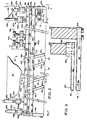
- the electrode assembly 50 employing electrode structures of the present invention in a capacity as both the charge electrodes 26 and deflection electrode 28 will be better understood by reference to accompanying FIGURES 2-4 and the description thereof which follows. Although reference will be made to the electrode assembly 50 as comprising both one of the charge electrodes 26 and a deflection electrode 28 each in accordance with this.invention, it is contemplated that the structural features of the present invention could be embodied in the fluid jet apparatus 10 as either a charge or a deflection electrode alone in dependence -upon the desired printing result upon substrate 32 as was briefly mentioned above.
- charge electrodes -26 are functionally similar to the structural features of deflection electrode 28, only those structures relating to charge electrodes 26 will be described below. Wherever possible, those structures of deflection electrodes 28 will, however,- be parenthetically noted along with those structures of charge electrodes 26 to which they correspond. It should also be understood that both charge electrodes. 26 shown in FIGURE 1 are identical to (but mirror images of) one another and thus only the charge electrode 26 which is associated with deflection electrode 28 via assembly 50 will be described in detail below.
- charge electrode 26 (28) includes a flexible and tensionable electrode member 52 (54) tensioned between a pair of mounting arms 56a, 56b (58a, 58b).
- the arms 56a, 56b (58a, 58b) are themselves mounted to cross support member 60 (62) so that the arms 56a, 56b (58a, 58b) are maintained in spaced relationship relative to one another.
- Arm 56a (58a) is rigidly connected to cross-support member 60 (62) so as to be immovable relative thereto while arm 56b (58b) is pivotally connected to cross-support member 60 (62) by means of pivot pin assembly 64 (66).
- Tension assembly 70 (72) is operatively coupled to cross-support 60 (62) and is shown in greater detail in FIGURE 2.
- Tension assembly 70 (72) includes a compression spring 70a exerting a bias force between arm 56b and subsupport 70b (72b).
- An adjusting bolt 70c (72c) and nut 70d are threadably engaged with one another and permit the bias force exerted upon arm 56b to be selectively adjustable in dependence upon selective turning movement being applied to bolt 70c (72c). Accordingly, the bias force exerted upon arm 56b by compression spring 70a forcibly urges arm 56b to be pivotally moved outwardly- away from its opposing rigidly-fixed arm 56a thereby maintaining the ribbon electrode member 52 in a tensioned state between the two arms 56a, 56b.
- the ribbon electrode 54 is maintained in a tensioned state between arms 58a, 58b by means of tension assembly 72 in a like manner to that of tension assembly 70 even though its corresponding structure is not entirely shown in detail in the accompanying Figures.
- the tension assembly 70 (72) maintains ribbon electrode member 52 (54) in a tensioned state between arm pairs 56a, 56b, (58a, 58b) while automatically compensating for e.g. thermal relaxation of ribbon electrode member 52 (54) which may occur during usage by virtue of the outward biased displacement of pivotally mounted arm member 56b (58b) relative to its opposing immovably fixed arm 56a (58a).
- Cross-support member 60 (62) includes intermediate arms 80 (82) pivotally mounted thereto.
- Each intermediate arm 80 (82) includes a terminal end 80a (82a) which is in operative contact with ribbon electrode member 52 (54).
- the intermediate-arms 80 (82) are pivotally mounted to cross-support member 60 (62) by conventional bolts, pivot pins or the like generally shown by reference numeral 80b (82b).
- reference numeral 80b 82b
- At least one intermediate arm 80 (82) is provided so as to effectively shorten the "free length" of the ribbon electrode 52 (54) - that is, to establish at least first and second sublengths of ribbon electrode 52 (54) between the contact of the terminal end 80a (82a) and each of the mounting arms 56a, 56b (58a, 58b).
- the electrode member 52 (54) When the electrode member 52 (54) is utilized in the printing of textile substrates, it must span the cross-machine width of the textile substrate (typically about 1.8 meters) and thus, under such circumstances, it is desirable to utilize plural intermediate arms 80 (82) as is shown in the accompanying drawings.
- N arms 80 (82) are utilized, N+1 sublengths of ribbon electrode 52 (54) are established between adjacent ones of intermediate arms 80 (82) and between the outermost ones of intermediate arms 80 (82) and a respective one of mounting arms 56a, 56b (58a, 58b). It is preferred that the axial length dimensions of the sublengths -be unequal relative to one another to more effectively prevent vibration of one sublength affecting vibration of an adjacent sublength or sublengths.
- the mounting arms 56a, 56b and 58a, 58b and intermediate arms 80, 82 are each preferably formed entirely from a substantially rigid electrically-insulating material (e.g. nylon) so as to not only electrically isolate electrode member 52 and electrode member 54 from one another but also to electrically isolate- each electrode member 52 and 54 from the other metal structural members comprising assembly 50.
- the electrode members 52, 54 can thus be connected to appropriate voltage drive sources (not shown) by means well known to those in the electrical arts, for example, by connecting leads from the appropriate voltage drive sources to mounting screws .52a and 54a, respectively.
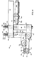
- Adjustment assembly 90a (90b) operatively coupled to cross-support member 60 (62) as can be seen with greater clarity in FIGURE 5.
- Adjustment assembly 90a (92b) includes a mounting bracket 92a (92b) fixed to the upper support member 94.
- a threaded adjustment shaft 96a (96b) is threadably coupled to bracket 92a (92b) and includes a knurled knob 98a (98b) at a rearward end thereof so that adjusting shaft 96a (96b) can be turned manually to effect displacement forwardly and rearwardly (arrow 100) of shaft 96a (96b) relative to bracket 92a (92b).
- the forward end of shaft 96a (96b) is coupled to cross-support 60 (62) by means of locknuts 102a (102b) and compression spring 104a (104b), the latter being biasingly compressed between locknuts 102a (104a) on the one hand and cross-support member 60 (62) on the other hand.
- a lock washer 106a (106b) is also. provided on-the rearward side of cross-support member 60 (62).
- the shaft 96a slidably passes through aperture 98 defined in cross-support 62 so that turning movement of shaft 96a will not affect cross-support 62.
- Cross-support member 60 (62) is itself coupled to frame support 94 so as to permit movement forwardly and rearwardly relative to the droplet stream (arrow 100).
- a bolt 108a (108b) is threadably coupled to cross-support member 60 (62) and is slidably received within slot 110a (110b) defined in frame support 94.
- a washer 112a (112b) provides a bearing surface against which the bias force of compression spring 114a (114b) can be exerted, the compression spring 114a (114b) being disposed between head 116a (116b) of bolt 108a (108b) and washer 112a (112b).
- bolts 108a can be slightly loosened to permit slidable movement of cross-support member 60 (62) relative to frame support 94 in the - direction of arrow 100 in response to turning movement being manually - applied to knob 98a (98b).
- cross-support member 60 (62) is selectively moved forwardly or rearwardly relative tp the droplet streams also in the direction of arrow 100.
- a plurality of the bolt/spring assemblies 108a/110a (108b/110b) are disposed axially along the length of cross-support member 60 (62).
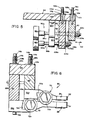
- a pair of calibrators 120a (120b) are preferably provided in operative contact with cross-support number 60 as can be seen more clearly in FIGURE 2.
- Calibrator 120a (120b) (see FIGURE 4) is fixed to frame support 94 by means of L-shaped bracket 122a (122b) so that calibrator 120a (120b) is disposed rearwardly of cross-support member 60 (62).
- Calibrator 120a (120b) includes a feeler arm 124a (124b) in contact with cross-support member 60 (62) and a vernier scale 126a (126b).
- a biasing spring housed within cylinder 128a (128b) biases vernier scale 126a and thus feeler arm 124a (124b) so as to maintain contact between cross-support member 60 (62) and feeler arm 124a (124b).
- the amount of movement can be visually determined by reference to vernier scale 126a (126b) in contact with cross-support member 60 (62). Correct alignment and placement of electrode member 52 (54) relative to the droplet stream is thereby insured. Once the correct positioning and alignment of electrode member 52 (54) is achieved, bolts 108a (108b) are threadably tightened so as to maintain cross-support member 60 (62) in its properly aligned position.
Landscapes
- Particle Formation And Scattering Control In Inkjet Printers (AREA)
Applications Claiming Priority (2)
| Application Number | Priority Date | Filing Date | Title |
|---|---|---|---|
| US06/786,124 US4639737A (en) | 1985-10-10 | 1985-10-10 | Tensionable electrodes for charging and/or deflecting fluid droplets in fluid-jet marking apparatus |
| US786124 | 1985-10-10 |
Publications (1)
| Publication Number | Publication Date |
|---|---|
| EP0221671A1 true EP0221671A1 (de) | 1987-05-13 |
Family
ID=25137653
Family Applications (1)
| Application Number | Title | Priority Date | Filing Date |
|---|---|---|---|
| EP86307518A Withdrawn EP0221671A1 (de) | 1985-10-10 | 1986-10-01 | Dehnbare Elektroden zum Aufladen und/oder zum Ablenken von Flüssigkeitströpfchen für Flüssigkeitsstrahl-Markierapparate |
Country Status (6)
| Country | Link |
|---|---|
| US (1) | US4639737A (de) |
| EP (1) | EP0221671A1 (de) |
| JP (1) | JPS62117755A (de) |
| CN (1) | CN86107076A (de) |
| AU (1) | AU579944B2 (de) |
| CA (1) | CA1289810C (de) |
Families Citing this family (2)
| Publication number | Priority date | Publication date | Assignee | Title |
|---|---|---|---|---|
| US4845512A (en) * | 1988-10-12 | 1989-07-04 | Videojet Systems International, Inc. | Drop deflection device and method for drop marking systems |
| GB9626787D0 (en) * | 1996-12-23 | 1997-02-12 | Domino Printing Sciences Plc | Continuous inkjet print head |
Citations (3)
| Publication number | Priority date | Publication date | Assignee | Title |
|---|---|---|---|---|
| US4234884A (en) * | 1979-03-01 | 1980-11-18 | The Mead Corporation | Ink jet printer assembly and alignment of printer components |
| US4523202A (en) * | 1981-02-04 | 1985-06-11 | Burlington Industries, Inc. | Random droplet liquid jet apparatus and process |
| US4538157A (en) * | 1983-02-23 | 1985-08-27 | The Mead Corporation | Fluid jet printer and method of operation |
Family Cites Families (17)
| Publication number | Priority date | Publication date | Assignee | Title |
|---|---|---|---|---|
| US3596275A (en) * | 1964-03-25 | 1971-07-27 | Richard G Sweet | Fluid droplet recorder |
| US3373437A (en) * | 1964-03-25 | 1968-03-12 | Richard G. Sweet | Fluid droplet recorder with a plurality of jets |
| CH486273A (fr) * | 1967-10-19 | 1970-02-28 | Max Kaltenbach Roger | Procédé de formation de gouttelettes uniformes d'un diamètre déterminé, appareil pour la mise en oeuvre de ce procédé et application de ce procédé à la fabrication d'un produit granulé |
| US3560988A (en) * | 1968-10-18 | 1971-02-02 | Mead Corp | High speed precision placement of liquid drops |
| US3701997A (en) * | 1971-03-30 | 1972-10-31 | Alden Res Found | Facsimile recorder and moving electrode therefor |
| US3701476A (en) * | 1971-10-14 | 1972-10-31 | Mead Corp | Drop generator with rotatable transducer |
| BE790064A (fr) * | 1971-10-14 | 1973-02-01 | Mead Corp | Generateur de gouttes pour dispositif d'enregistrement. |
| US3787883A (en) * | 1972-12-20 | 1974-01-22 | Mead Corp | Deflection electrode assembly for a jet drop recorder |
| US3836913A (en) * | 1972-12-20 | 1974-09-17 | Mead Corp | Recording head for a jet array recorder |
| US3805273A (en) * | 1972-12-20 | 1974-04-16 | Mead Corp | Yoke mounted jet drop recording head |
| US3813675A (en) * | 1973-03-28 | 1974-05-28 | Mead Corp | Catching apparatus for a jet drop recorder |
| US4031563A (en) * | 1976-01-29 | 1977-06-21 | The Mead Corporation | Jet drop recording head having an improved porous deflection ribbon |
| US4085409A (en) * | 1976-06-01 | 1978-04-18 | The Mead Corporation | Method and apparatus for ink jet printing |
| US4081804A (en) * | 1976-07-12 | 1978-03-28 | The Mead Corporation | Catcher mounting apparatus for a jet drop printer |
| US4119973A (en) * | 1977-09-06 | 1978-10-10 | The Mead Corporation | Fault detection and compensation circuit for ink jet printer |
| DE2812637C3 (de) * | 1978-03-22 | 1981-02-12 | Siemens Ag, 1000 Berlin Und 8000 Muenchen | Anordnung zum selbsttätigen Einziehen einer Diskette in ein Diskettenlaufwerk |
| US4229748A (en) * | 1979-02-16 | 1980-10-21 | The Mead Corporation | Jet drop printer |
-
1985
- 1985-10-10 US US06/786,124 patent/US4639737A/en not_active Expired - Fee Related
-
1986
- 1986-09-18 AU AU62910/86A patent/AU579944B2/en not_active Ceased
- 1986-09-22 JP JP61224053A patent/JPS62117755A/ja active Granted
- 1986-09-29 CA CA000519353A patent/CA1289810C/en not_active Expired - Fee Related
- 1986-10-01 EP EP86307518A patent/EP0221671A1/de not_active Withdrawn
- 1986-10-09 CN CN198686107076A patent/CN86107076A/zh active Pending
Patent Citations (3)
| Publication number | Priority date | Publication date | Assignee | Title |
|---|---|---|---|---|
| US4234884A (en) * | 1979-03-01 | 1980-11-18 | The Mead Corporation | Ink jet printer assembly and alignment of printer components |
| US4523202A (en) * | 1981-02-04 | 1985-06-11 | Burlington Industries, Inc. | Random droplet liquid jet apparatus and process |
| US4538157A (en) * | 1983-02-23 | 1985-08-27 | The Mead Corporation | Fluid jet printer and method of operation |
Also Published As
| Publication number | Publication date |
|---|---|
| CA1289810C (en) | 1991-10-01 |
| AU579944B2 (en) | 1988-12-15 |
| AU6291086A (en) | 1987-04-16 |
| JPH0568355B2 (de) | 1993-09-28 |
| JPS62117755A (ja) | 1987-05-29 |
| CN86107076A (zh) | 1987-04-29 |
| US4639737A (en) | 1987-01-27 |
Similar Documents
| Publication | Publication Date | Title |
|---|---|---|
| CA1156708A (en) | Field replaceable modules for ink jet head assembly | |
| US4010834A (en) | Printing device comprising a distance member | |
| US5608430A (en) | Printer print head positioning apparatus and method | |
| US3877036A (en) | Precise jet alignment for ink jet printer | |
| CA1233446A (en) | Two-dimensional ink jet adjustment mechanism | |
| ES2075650T3 (es) | Procedimiento de proyeccion de liquido y dispositivo de impresion de alta resolucion en una impresora por chorro de tinta continuo en la que se aplica este procedimiento. | |
| JPH0631925A (ja) | インクジェットプリンタの部品の配列方法及び配列構造 | |
| DE3878935T2 (de) | Troepfchenerzeugung durch wanderwellen fuer farbstrahlschreiber. | |
| US4725851A (en) | Method and assembly for mounting fluid-jet orifice plate | |
| JPS61100470A (ja) | 放滴距離補正付インクジエツトプリンタ | |
| US4639737A (en) | Tensionable electrodes for charging and/or deflecting fluid droplets in fluid-jet marking apparatus | |
| US4736209A (en) | Tensionable ground electrode for fluid-jet marking apparatus | |
| CA1296948C (en) | Print head gap adjustment mechansim | |
| EP0333768A1 (de) | Druckerkopfvorrichtung | |
| CA1224669A (en) | Ink jet printer and method of start-up and shutdown thereof | |
| US4849772A (en) | Ink jet printer with front reference platen assembly | |
| EP0966357A1 (de) | Drucker mit koninuierlichem tintenstrahl | |
| US4345260A (en) | Ink jet printer with carriage velocity compensation | |
| JPH0542746A (ja) | 印刷ヘツドの装着及び方位角度調整装置 | |
| EP0214720A1 (de) | Verfahren und Anordnung für die Montage einer Tintenstrahldüsenplatte | |
| US3981236A (en) | Printhead for impact printer | |
| US4404901A (en) | Striker assembly for line printers | |
| WO1998028153A1 (en) | Continuous inkjet printer | |
| WO1998028152A1 (en) | Flexure for continuous inkjet printer | |
| US4134336A (en) | Half-herringbone support for restricting sideways vibration of comb hammers |
Legal Events
| Date | Code | Title | Description |
|---|---|---|---|
| PUAI | Public reference made under article 153(3) epc to a published international application that has entered the european phase |
Free format text: ORIGINAL CODE: 0009012 |
|
| AK | Designated contracting states |
Kind code of ref document: A1 Designated state(s): AT BE CH DE ES FR GB GR IT LI LU NL SE |
|
| ITCL | It: translation for ep claims filed |
Representative=s name: MODIANO & ASSOCIATI S.R.L. |
|
| 17P | Request for examination filed |
Effective date: 19871102 |
|
| 17Q | First examination report despatched |
Effective date: 19890524 |
|
| STAA | Information on the status of an ep patent application or granted ep patent |
Free format text: STATUS: THE APPLICATION IS DEEMED TO BE WITHDRAWN |
|
| 18D | Application deemed to be withdrawn |
Effective date: 19910105 |
|
| RIN1 | Information on inventor provided before grant (corrected) |
Inventor name: SUTERA, RICHARD |