EP0221711A2 - Lichtwellenleiter-Übertragungssysteme mit Raman-Verstärkungsmitteln - Google Patents
Lichtwellenleiter-Übertragungssysteme mit Raman-Verstärkungsmitteln Download PDFInfo
- Publication number
- EP0221711A2 EP0221711A2 EP86308101A EP86308101A EP0221711A2 EP 0221711 A2 EP0221711 A2 EP 0221711A2 EP 86308101 A EP86308101 A EP 86308101A EP 86308101 A EP86308101 A EP 86308101A EP 0221711 A2 EP0221711 A2 EP 0221711A2
- Authority
- EP
- European Patent Office
- Prior art keywords
- radiation
- fiber
- pump
- optical fiber
- communications system
- Prior art date
- Legal status (The legal status is an assumption and is not a legal conclusion. Google has not performed a legal analysis and makes no representation as to the accuracy of the status listed.)
- Withdrawn
Links
Images


Classifications
-
- H—ELECTRICITY
- H04—ELECTRIC COMMUNICATION TECHNIQUE
- H04B—TRANSMISSION
- H04B10/00—Transmission systems employing electromagnetic waves other than radio-waves, e.g. infrared, visible or ultraviolet light, or employing corpuscular radiation, e.g. quantum communication
- H04B10/29—Repeaters
- H04B10/291—Repeaters in which processing or amplification is carried out without conversion of the main signal from optical form
- H04B10/2912—Repeaters in which processing or amplification is carried out without conversion of the main signal from optical form characterised by the medium used for amplification or processing
- H04B10/2916—Repeaters in which processing or amplification is carried out without conversion of the main signal from optical form characterised by the medium used for amplification or processing using Raman or Brillouin amplifiers
Definitions
- This invention pertains to the field of optical communications and involves optical fiber communications systems comprising Raman Amplification means.
- Raman amplification is possible in fibers other than silica-based (i.e., containing at least 50% by weight, typically > 80% by weight, SiO2) optical fibers, for the sake of concreteness, the exposition below will frequently refer to, and use material constants appropriate for, silica-based fiber.
- Such fibers have two loss minima in the approximate range 1.2-1.6 ⁇ m, and therefore communications systems that use silica-based fiber frequently use signal radiation whose wavelength lies in that range.
- S timulated R aman S cattering is known to produce substantial gain in fused silica for frequency shifts in the range from about 100 to about 600 cm ⁇ 1, with the maximum gain occurring for a frequency shift of about 450 cm ⁇ 1.
- SBS S timulated B rillouin S cattering
- SBS can take place in optical fibers, and that such scattering can have a deleterious effect on systems performance, due principally to the fact that SBS can cause severe fluctuations in the pump intensity, which cause corresponding fluctuations in the Raman gain and to the fact that SBS can result in pump depletion.
- SBS can have a peak gain that is several hundred times that for SRS, per unit frequency of pump radiation, but SBS linewidths are typically very narrow, e.g., of the order of 20 MHz.
- the technique involves imposition of phase modulation on the optical field launched into the fiber so as to reduce the SBS gain. This is achieved, for instance, by placing between the laser and the fiber a periodically driven optical phase modulator, or by using a mode-beating effect produced when the radiation field comprises two discrete but closely spaced optical frequencies. This, it is suggested, could be achieved by using two single-frequency lasers operating at slightly different wavelengths, or perhaps more easily by using a single laser which is arranged to operate in two longitudinal modes. This principle was applied by J. Hegarty et al, Electronics Letters , Vol. 21(7) 1985, pp. 290-292, who used a laser operating in two modes separated by 2 GHz.
- SRS can be used to amplify "linear" pulses, i.e., pulses in which no particular relationship between pulse peak power and pulse peak width is required
- amplification by SRS can be advantageously used in soliton communications systems.
- A. Hasegawa et al have shown ( Applied Physics Letters , Vol. 23 (3), pp. 142-144 (1973)) that under certain conditions shape-maintaining pulses can exist in single mode optical fiber. Such pulses are termed solitons, and, in silica-based fiber, typically have center wavelengths in the range 1.45-1.60 ⁇ m. The existence of solitons has been experimentally demonstrated (L.F. Mollenauer et al, Physical Review Letters , Vol.
- the present invention provides a communications system as set out in claim 1.
- a fiberguide communications system to be described comprises a broadband source of pump radiation, or, preferably, a multiplicity of sources of pump radiation, will source characteristics such as center wavelengths and spectral widths chosen such that the pump radiation intensity of the fiber core (optical fiber comprises a core of relatively higher refractive index, and, contactingly surrounding the core, a cladding of relatively lower refractive index) at any given wavelength does not exceed a critical value, to be defined below.
- the multiplicity of pump radiation sources can comprise discrete sources, e.g., discrete semiconductor lasers, gas lasers, or other sources of coherent or noncoherent radiation, or an array of devices integrated on a chip. In a currently preferred embodiment, the sources are discrete, semiconductor lasers.
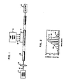
- FIG. 1 An exemplary communications system according to the invention is schematically depicted in FIG. 1, wherein 10 is an optical fiber, typically single mode fiber, 11 is a source of electromagnetic radiation 12 (of wavelength ⁇ 0, the signal radiation), 13 refers to means for coupling 12 into the fiber, and 14 to means for detecting signal radiation, e.g., a photodetector. Furthermore, 15 refers to the array of pump radiation sources, 16 to the totality of pump radiation emitted by all active sources of 15, and 17 to means for coupling the pump radiation into the fiber.
- Such well-known parts of a communications system as drive electronics, detector electronics, splices, attenuators, output means, etc., are not shown in FIG. 1.
- a soliton system one typically provides means for monitoring and adjusting the pump power and/or the signal power such that the signal pulses remain solitons throughout their transmission through the fiber link.
- Such means can be conventional.
- the pump radiation can be injected into the fiber such that it is co-propagating or counterpropagating with the signal radiation, or it can be injected such that a portion co-propagates whereas the remainder counter-propagates.
- the signal radiation is in pulse form, and the pump radiation can be either CW or pulsed. Use of pulsed pump radiation is frequently not advantageous with co-propagating signal pulses.
- the pump power is spread over a spectral region such that the intensity of pump radiation at any given wavelength ⁇ p in the fiber core is less than I c , the critical intensity for SBS at that wavelength.
- I c For purposes of this application we define I c to be that average radiation intensity in the core of an optical fiber (in the spectral interval that is centred at a wavelength ⁇ p and that is equal in width to the Brillouin linewidth in the fiber at ⁇ p ) that results in conversion of 10% of the radiation in the spectral interval of stimulated Brillouin radiation.
- the "Brillouin linewidth" associated with an optical fiber is the FWHM ( f ull w idth at h alf m aximum) of the Brillouin spontaneous scattering spectrum in the fiber, as determined with a narrow line source of radiation.
- a line source is "narrow” if the source line width is much less than the Brillouin linewidth.
- the Brillouin linewidth of 1.46 ⁇ m pump radiation is about 18 MHz. If the fiber is single mode fiber with an 8 ⁇ m core diameter and a loss of about 0.2 dB/km, I c ⁇ 0.04 mW ( ⁇ m)2. This implies that the pump power in any 18 MHz wide spectral region at about 1.46 ⁇ m is not to exceed about 2 mW.
- a method for calculating A eff can be found in Optical Fiber Telecommunications , S. E. Miller and A. G. Chynoweth, editors, Academic Press, 1979, pp. 127-135, especially page 130.
- the thus calculated value of A eff typically is sufficiently close to the core area size of a single mode fiber such that for most purposes it is permissible to substitute the value of the core area A for A eff .
- semiconductor lasers typically have a multi-line emission spectrum, as exemplified in FIG. 2. Each relatively narrow peak 20 is associated with a longitudinal mode of the laser. The mode spacing depends on the laser design, especially the resonator length and the refractive index of the active region, and frequently is of the order 0.1 nm.
- FIG. 2 also shows the envelope 21 of the emission spectrum.
- the intensity envelope of the output of a radiation source can be used to characterize the source output.
- the center wavelength and spectral width of a source are herein defined as the wavelength corresponding to the maximum in the intensity envelope and as the full width at half maximum of the intensity envelope, respectively.
- Semiconductor lasers without mode locking typically have spectral widths of the order of 5 cm ⁇ 1, or equivalently, about 1 nm at ⁇ 1.5 ⁇ m.
- the linewidth of a single radiation mode, although narrow, is typically much greater than the Brillouin linewidth.
- the pump radiation is to have a finite spectral width such that the above stated intensity criterion is met at all wavelengths, it may be advantageous to use lasers having a large number of lasing modes and/or having relatively broad emission modes.
- the peak of the Raman gain coefficient is about 200 cm ⁇ 1 wide (with the region of gain being much wider, of the order of 500 cm ⁇ 1).
- FIGS. 3-6 show an optical fiber 10 carrying optical signals in one direction, and pump radiation in the opposite direction, whereas otherwise identical FIG. 4 shows co-propagating signal and pump radiation.
- FIGS. 5 and 6 show optical fiber carrying pump radiation in both directions, with FIG. 5 showing dividers 50 for splitting the pump radiation, and FIG. 6 illustrating the use of separate pump sources.
- FIG. 5 also indicates a unidirectional signal stream, whereas FIG. 6 shows bidirectional signal streams. It will be appreciated that the illustrated systems are exemplary only, and that other schemes are also possible.
- FIGS. 3 shows an optical fiber 10 carrying optical signals in one direction, and pump radiation in the opposite direction
- FIG. 4 shows co-propagating signal and pump radiation.
- FIGS. 5 and 6 show optical fiber carrying pump radiation in both directions, with FIG. 5 showing dividers 50 for splitting the pump radiation, and FIG. 6 illustrating the use of separate pump sources.
- FIG. 5 also indicates a unidirectional signal stream, whereas FIG. 6 shows bidirectional signal streams. It will be appreciated that
- reference numeral 15 refers to an aggregate of pump sources, and 30 to optical fiber serving to guide the pump radiation to a coupler 31, (and, in FIG. 5, to a splitter 50).
- Coupler 31 serves to couple pump radiation onto the transmission fiber without coupling out significant amounts of signal radiation.
- a system typically also requires means for coupling the outputs of the battery of pump sources onto fiber 30.
- Exemplary means for achieving this are schematically depicted in FIG. 7, in which 151, 152, ... 15n indicate n sources of pump radiation 171, 172, ... 17 n, respectively.
- the n beams of pump radiation are directed onto the surface of optical grating 70.
- the grating serves to combine the n individual beams into single beam 16 which is coupled into fiber 30 by appropriate coupling means 71.
- 151-154 refers to four (out of a battery of n ) individual pump sources that emit polarized radiation, with, for instance, sources 151 and 153 emitting radiation of center wavelength ⁇ p1 and ⁇ p3 , respectively, that is polarized perpendicular to some reference direction, and 152 and 154 radiation of wavelength ⁇ p2 and ⁇ p4 , respectively, that is polarized parallel to the reference direction.
- Fibers 82 are of the polarization preserving type
- couplers 81 are polarization selective couplers
- coupler 80 is of the previously referred-to wavelength dependent type.
- the invention can also be practiced with a broadband source whose output meets the intensity criterion.
- a solid state diode could be used as such a broadband source, provided that means for efficiently coupling its output to a single mode optical fiber can be devised.
- the optical fiber transmission channel consists of single mode dispersion shifted silica-based fiber having a loss of 0.18 dB/km at 1.56 ⁇ m and of 0.29 dB/km at 1.46 ⁇ m, a dispersion of 2ps/nm km, an effective core area of 25 ( ⁇ m)2, and has a length of 2200 km.
- the pulses are coupled into the fiber, the laser being adjusted such that the coupled-in pulses have a peak power of 27 mW, are substantially of sech-shape, and have a pulse width of 7.5 ps.
- pump radiation injection points At intervals of about 40 km along the fiber are located pump radiation injection points. At each of these points is located a battery of ten semiconductor laser pump radiation sources, with center wavelengths substantially regularly spaced throughout the wavelength interval 1.44 to 1.48 ⁇ m. The sources have an average halfwidth of 20 nm, and typically emit in about 10 modes.
- the total pump power coupled into the fiber at each injection point is ⁇ 40 mW, with the pump power in the fiber core everywhere being substantailly below 1.0 mW (with the intensity everywhere being substantially below 0.04 mW/( ⁇ m)2) for any wavelength region in the pump radiation spectrum that is equal to the Brillouin linewidth in this fiber, approximately equal to 18 MHz.
- the cw pump radiation is bidirectionally coupled into the fiber by means of a grating and a wavelength-dependent coupler.
- the Raman gain of the signal pulses over the 40 km amplifier spacing essentially equals the signal loss over this distance, resulting in stable transmission of the soliton pulses, with an error rate ⁇ 10 ⁇ 9/bit achievable for bit rates up to 13 Gbit/sec.
- the pulses are detected by conventional means.
Landscapes
- Physics & Mathematics (AREA)
- Electromagnetism (AREA)
- Engineering & Computer Science (AREA)
- Computer Networks & Wireless Communication (AREA)
- Signal Processing (AREA)
- Optical Communication System (AREA)
- Lasers (AREA)
Applications Claiming Priority (2)
| Application Number | Priority Date | Filing Date | Title |
|---|---|---|---|
| US06/791,915 US4699452A (en) | 1985-10-28 | 1985-10-28 | Optical communications system comprising Raman amplification means |
| US791915 | 1985-10-28 |
Publications (2)
| Publication Number | Publication Date |
|---|---|
| EP0221711A2 true EP0221711A2 (de) | 1987-05-13 |
| EP0221711A3 EP0221711A3 (de) | 1989-11-15 |
Family
ID=25155204
Family Applications (1)
| Application Number | Title | Priority Date | Filing Date |
|---|---|---|---|
| EP86308101A Withdrawn EP0221711A3 (de) | 1985-10-28 | 1986-10-20 | Lichtwellenleiter-Übertragungssysteme mit Raman-Verstärkungsmitteln |
Country Status (4)
| Country | Link |
|---|---|
| US (1) | US4699452A (de) |
| EP (1) | EP0221711A3 (de) |
| JP (1) | JPS62102585A (de) |
| CA (1) | CA1249030A (de) |
Cited By (6)
| Publication number | Priority date | Publication date | Assignee | Title |
|---|---|---|---|---|
| EP0392493A1 (de) * | 1989-04-14 | 1990-10-17 | Nippon Telegraph And Telephone Corporation | Optischer Regenerator und seine Verwendung in einem optischen Netzwerk |
| EP0392490A1 (de) * | 1989-04-14 | 1990-10-17 | Nippon Telegraph And Telephone Corporation | Optische Verzweigungsvorrichtung und deren Verwendung in einem optischen Netzwerk |
| FR2657478A1 (fr) * | 1990-01-23 | 1991-07-26 | Stc Plc | Procede et appareil de transmission optique, et amplificateur pour leur mise en óoeuvre. |
| EP0339840A3 (de) * | 1988-04-25 | 1991-09-04 | AT&T Corp. | Optisches Übertragungssystem mit Raman-Verstärkungsmitteln |
| EP0421675A3 (en) * | 1989-10-06 | 1992-03-18 | American Telephone And Telegraph Company | Distributed amplification for lightwave transmission system |
| EP0408905A3 (en) * | 1989-07-21 | 1992-07-08 | Societa Cavi Pirelli S.P.A. | Optical fiber telecommunication line comprising amplifiers of the transmitted signals and amplifiers for said line |
Families Citing this family (67)
| Publication number | Priority date | Publication date | Assignee | Title |
|---|---|---|---|---|
| US4778238A (en) * | 1985-08-01 | 1988-10-18 | Hicks John W | Optical communications systems and process for signal amplification using stimulated brillouin scattering (SBS) and laser utilized in the system |
| US4741587A (en) * | 1986-02-20 | 1988-05-03 | American Telephone And Telegraph Company, At&T Bell Laboratories | Optical communications system and method for the generation of a sequence of optical pulses by means of induced modulational instability |
| US4820016A (en) * | 1986-02-21 | 1989-04-11 | American Telephone And Telegraph Company, At&T Bell Laboratories | Waveguide-containing communications and sensing systems |
| CA1298112C (en) * | 1986-10-20 | 1992-03-31 | Nicholas John Doran | Optical device |
| US4880295A (en) * | 1987-10-21 | 1989-11-14 | Hughes Aircraft Company | Optical device enhancement method and apparatus by control of stimulated brillouin scattering gain |
| GB8728854D0 (en) * | 1987-12-10 | 1988-01-27 | British Telecomm | Optical device |
| US4941726A (en) * | 1988-08-31 | 1990-07-17 | The Unites States Of America As Represented By The Secretary Of The Navy | Tapered fiber amplifier |
| US4867518A (en) * | 1988-08-31 | 1989-09-19 | The United States Of America As Represented By The Secretary Of The Navy | All-fiber SFPM amplifier |
| US4913507A (en) * | 1988-09-08 | 1990-04-03 | The United States Of America As Represented By The Secretary Of The Navy | Mode field conditioner |
| US5257173A (en) * | 1989-12-13 | 1993-10-26 | Stanley Electric Co., Ltd. | Light irradiating apparatus having light emitting diode used as light source |
| US5039199A (en) * | 1989-12-29 | 1991-08-13 | At&T Bell Laboratories | Lightwave transmission system having remotely pumped quasi-distributed amplifying fibers |
| US5181134A (en) * | 1991-03-15 | 1993-01-19 | At&T Bell Laboratories | Photonic cross-connect switch |
| US5218655A (en) * | 1992-05-29 | 1993-06-08 | At&T Bell Laboratories | Article comprising an optical waveguide with in-line refractive index grating |
| US5359450A (en) * | 1992-06-25 | 1994-10-25 | Synchronous Communications, Inc. | Optical transmission system |
| US5253104A (en) * | 1992-09-15 | 1993-10-12 | At&T Bell Laboratories | Balanced optical amplifier |
| US5329396A (en) * | 1992-10-28 | 1994-07-12 | At&T Bell Laboratories | Reduction of stimulated brillouin scattering in a fiber optic transmission system |
| GB2272102B (en) * | 1992-10-30 | 1996-02-07 | Northern Telecom Ltd | Optical amplifier |
| DE69637562D1 (de) * | 1995-03-20 | 2008-07-24 | Fujitsu Ltd | Verfahren und Vorrichtung zur optischen Signalverarbeitung |
| CN1060572C (zh) * | 1996-11-13 | 2001-01-10 | 陈祖培 | 熔锥型高密度波分复用器 |
| US5764831A (en) * | 1997-04-15 | 1998-06-09 | Institut National D'optique | Grating assisted fused fiber filter |
| US6693737B2 (en) | 1998-03-24 | 2004-02-17 | Xtera Communications, Inc. | Dispersion compensating nonlinear polarization amplifiers |
| US6760148B2 (en) | 1998-03-24 | 2004-07-06 | Xtera Communications, Inc. | Nonlinear polarization amplifiers in nonzero dispersion shifted fiber |
| CA2335289C (en) | 1998-06-16 | 2009-10-13 | Mohammed Nazrul Islam | Fiber-optic compensation for dispersion, gain tilt, and band pump nonlinearity |
| US6359725B1 (en) | 1998-06-16 | 2002-03-19 | Xtera Communications, Inc. | Multi-stage optical amplifier and broadband communication system |
| US6335820B1 (en) | 1999-12-23 | 2002-01-01 | Xtera Communications, Inc. | Multi-stage optical amplifier and broadband communication system |
| US6885498B2 (en) | 1998-06-16 | 2005-04-26 | Xtera Communications, Inc. | Multi-stage optical amplifier and broadband communication system |
| US6839522B2 (en) | 1998-07-21 | 2005-01-04 | Corvis Corporation | Optical signal varying devices, systems and methods |
| US6344922B1 (en) * | 1998-07-21 | 2002-02-05 | Corvis Corporation | Optical signal varying devices |
| US6115174A (en) | 1998-07-21 | 2000-09-05 | Corvis Corporation | Optical signal varying devices |
| EP2306605B1 (de) * | 1998-07-23 | 2012-05-23 | The Furukawa Electric Co., Ltd. | Pumpeinheit für einen Ramanverstärker und Ramanverstärker, der dieselbe aufweist |
| US6181464B1 (en) * | 1998-12-01 | 2001-01-30 | Tycom (Us) Inc. | Low noise Raman amplifier employing bidirectional pumping and an optical transmission system incorporating same |
| US6356383B1 (en) * | 1999-04-02 | 2002-03-12 | Corvis Corporation | Optical transmission systems including optical amplifiers apparatuses and methods |
| GB9911665D0 (en) * | 1999-05-19 | 1999-07-21 | Cit Alcatel | An optical amplifier |
| US6587261B1 (en) * | 1999-05-24 | 2003-07-01 | Corvis Corporation | Optical transmission systems including optical amplifiers and methods of use therein |
| CA2339115A1 (en) * | 1999-05-31 | 2000-12-07 | The Furukawa Electric Co., Ltd. | Raman amplification system and optical signal transmission method using the same |
| US6611370B2 (en) | 1999-07-23 | 2003-08-26 | The Furukawa Electric Co., Ltd. | Raman amplifier system, apparatus and method for identifying, obtaining and maintaining an arbitrary Raman amplification performance |
| US6611369B2 (en) | 1999-09-06 | 2003-08-26 | Furukawa Electric Co., Ltd. | Optical signal amplifier |
| FR2800219B1 (fr) * | 1999-10-22 | 2006-06-30 | Algety Telecom | Procede d'ajustement de puissance pour un systeme de transmission optique a multiplexage en longueur d'onde |
| FR2800218B1 (fr) * | 1999-10-22 | 2002-01-11 | Algety Telecom | Systeme de transmission par fibre optique utilisant des impulsions rz |
| EP1170628B1 (de) * | 2000-01-14 | 2018-08-01 | The Furukawa Electric Co., Ltd. | Ramanverstärker |
| US6344925B1 (en) | 2000-03-03 | 2002-02-05 | Corvis Corporation | Optical systems and methods and optical amplifiers for use therein |
| JP2002062552A (ja) * | 2000-08-18 | 2002-02-28 | Sumitomo Electric Ind Ltd | ラマン増幅器および光通信システム |
| JP2002135212A (ja) * | 2000-10-20 | 2002-05-10 | Fujitsu Ltd | 双方向伝送可能な光波長分割多重伝送システム |
| US6678294B1 (en) * | 2000-11-06 | 2004-01-13 | Northrop Grumman Corporation | Distributed feedback laser apparatus for avoiding stimulated brillouin scattering |
| GB0031508D0 (en) * | 2000-12-22 | 2001-02-07 | Cit Alcatel | Broadband raman amplifier |
| KR100367085B1 (ko) * | 2000-12-27 | 2003-01-09 | 한국전자통신연구원 | 광선로 손실변화 보상장치 |
| US6417958B1 (en) | 2001-01-24 | 2002-07-09 | Lucent Technologies Inc. | WDM optical communication system using co-propagating Raman amplification |
| JP2002229083A (ja) * | 2001-01-31 | 2002-08-14 | Sumitomo Electric Ind Ltd | 光通信システム |
| EP1229675A3 (de) * | 2001-02-02 | 2004-09-22 | The Furukawa Electric Co., Ltd. | Pumplichtquelle für Ramanverstärker und Ramanverstärker der diese verwendet |
| US6959021B2 (en) | 2001-02-07 | 2005-10-25 | Ocg Technology Licensing, Llc | Raman fiber laser |
| US6433922B1 (en) | 2001-02-26 | 2002-08-13 | Redc Optical Networks Ltd. | Apparatus and method for a self adjusting Raman amplifier |
| US20020167719A1 (en) * | 2001-04-20 | 2002-11-14 | Bo Pedersen | Method of pump wavelength combing for enhanced power dynamic range and redundancy broad band raman optical amplifier system |
| WO2002093704A1 (en) | 2001-05-15 | 2002-11-21 | Ocg Technology Licensing, Llc | Optical fiber and system containing same |
| AU2002316478A1 (en) * | 2001-07-02 | 2003-01-21 | Ogg Technology Licensing, Llc. | Multi-wavelength optical fiber |
| US6525870B1 (en) | 2001-07-26 | 2003-02-25 | Ciena Corporation | Method and system for controlling Raman gain flatness sensitivity to pump laser wavelength variation |
| WO2003014771A2 (en) * | 2001-08-03 | 2003-02-20 | Ocg Technology Licensing, Llc | Optical fiber amplifier |
| US6731423B1 (en) * | 2001-08-15 | 2004-05-04 | Neumann Information Systems Inc | Optical amplifier and method |
| US6836487B1 (en) | 2001-08-31 | 2004-12-28 | Nlight Photonics Corporation | Spectrally tailored raman pump laser |
| US6907051B1 (en) | 2001-08-31 | 2005-06-14 | Nlight Photonics Corporation | Dynamically spectrally tailored raman pump laser |
| EP1330056A1 (de) * | 2002-01-16 | 2003-07-23 | Lucent Technologies Inc. | Verfahren und Vorrichtung zur Ramanverstärkung in einem optischen Einrichtung |
| JP2004086143A (ja) * | 2002-06-28 | 2004-03-18 | Sumitomo Electric Ind Ltd | 光伝送システム |
| US7146110B2 (en) * | 2003-02-11 | 2006-12-05 | Optium Corporation | Optical transmitter with SBS suppression |
| US7206123B2 (en) * | 2003-09-08 | 2007-04-17 | The Furukawa Electric Co. Ltd. | Raman amplifier, pump source for use in a raman amplifier and method for amplifying an optical signal |
| US7901870B1 (en) | 2004-05-12 | 2011-03-08 | Cirrex Systems Llc | Adjusting optical properties of optical thin films |
| US7565084B1 (en) | 2004-09-15 | 2009-07-21 | Wach Michael L | Robustly stabilizing laser systems |
| GB2445771A (en) * | 2007-01-19 | 2008-07-23 | Gsi Group Ltd | A diode pumped CW laser |
| US20100183305A1 (en) * | 2009-01-16 | 2010-07-22 | Xtera Communications, Inc. | Optical communication using coupled optically pumped amplifiers |
Family Cites Families (7)
| Publication number | Priority date | Publication date | Assignee | Title |
|---|---|---|---|---|
| US4114112A (en) * | 1976-12-22 | 1978-09-12 | Northwestern University | Apparatus and method for efficient synthesis of laser light |
| US4616898A (en) * | 1980-03-31 | 1986-10-14 | Polaroid Corporation | Optical communication systems using raman repeaters and components therefor |
| JPS56165437A (en) * | 1980-05-26 | 1981-12-19 | Kokusai Denshin Denwa Co Ltd <Kdd> | Optical repeating system for optical communication |
| US4406516A (en) * | 1981-04-27 | 1983-09-27 | Bell Telephone Laboratories, Incorporated | Monomode fiberguide telecommunication system utilizing soliton pulses |
| US4558921A (en) * | 1982-02-25 | 1985-12-17 | At&T Bell Laboratories | Soliton fiber telecommunication systems |
| FI74371C (fi) * | 1982-06-04 | 1988-01-11 | British Telecomm | Optisk oeverfoering. |
| US4546476A (en) * | 1982-12-10 | 1985-10-08 | The Board Of Trustees Of The Leland Stanford Junior University | Fiber optic amplifier |
-
1985
- 1985-10-28 US US06/791,915 patent/US4699452A/en not_active Expired - Fee Related
-
1986
- 1986-10-20 EP EP86308101A patent/EP0221711A3/de not_active Withdrawn
- 1986-10-22 CA CA000521113A patent/CA1249030A/en not_active Expired
- 1986-10-28 JP JP61254838A patent/JPS62102585A/ja active Pending
Cited By (9)
| Publication number | Priority date | Publication date | Assignee | Title |
|---|---|---|---|---|
| EP0339840A3 (de) * | 1988-04-25 | 1991-09-04 | AT&T Corp. | Optisches Übertragungssystem mit Raman-Verstärkungsmitteln |
| EP0392493A1 (de) * | 1989-04-14 | 1990-10-17 | Nippon Telegraph And Telephone Corporation | Optischer Regenerator und seine Verwendung in einem optischen Netzwerk |
| EP0392490A1 (de) * | 1989-04-14 | 1990-10-17 | Nippon Telegraph And Telephone Corporation | Optische Verzweigungsvorrichtung und deren Verwendung in einem optischen Netzwerk |
| US5005937A (en) * | 1989-04-14 | 1991-04-09 | Nippon Telegraph And Telephone Corporation | Optical branching equipment and optical network using the same |
| US5083874A (en) * | 1989-04-14 | 1992-01-28 | Nippon Telegraph And Telephone Corporation | Optical repeater and optical network using the same |
| EP0408905A3 (en) * | 1989-07-21 | 1992-07-08 | Societa Cavi Pirelli S.P.A. | Optical fiber telecommunication line comprising amplifiers of the transmitted signals and amplifiers for said line |
| EP0742650A1 (de) * | 1989-07-21 | 1996-11-13 | PIRELLI CAVI S.p.A. | Lichtwellenleiternachrichtenübertragungsleitung mit Verstärker für die übertragenen Signale und Verstärker für diese Leitung |
| EP0421675A3 (en) * | 1989-10-06 | 1992-03-18 | American Telephone And Telegraph Company | Distributed amplification for lightwave transmission system |
| FR2657478A1 (fr) * | 1990-01-23 | 1991-07-26 | Stc Plc | Procede et appareil de transmission optique, et amplificateur pour leur mise en óoeuvre. |
Also Published As
| Publication number | Publication date |
|---|---|
| US4699452A (en) | 1987-10-13 |
| EP0221711A3 (de) | 1989-11-15 |
| JPS62102585A (ja) | 1987-05-13 |
| CA1249030A (en) | 1989-01-17 |
Similar Documents
| Publication | Publication Date | Title |
|---|---|---|
| US4699452A (en) | Optical communications system comprising Raman amplification means | |
| US4881790A (en) | Optical communications system comprising raman amplification means | |
| US6178038B1 (en) | Optical amplifier having an improved noise figure | |
| EP1130704B1 (de) | Optisches Übertragungssystem mit Raman-Verstärkung | |
| EP1063795B1 (de) | Optischer Verstärker, optisches Übertragungssystem mit einem optischen Verstärker und Verfahren zum Verstärken eines optischen Signals | |
| EP0504834B1 (de) | Optischer Sender | |
| US5329396A (en) | Reduction of stimulated brillouin scattering in a fiber optic transmission system | |
| US6414786B1 (en) | Method and apparatus for reducing polarization dependent gain in Raman amplification | |
| EP0485100B1 (de) | Optische Verstärker | |
| EP1022870B1 (de) | Optisches Übertragungssystem mit Ramanverstärkern mehrfacher Ordnungen | |
| JP3025210B2 (ja) | 光ファイバラマン増幅器を含む装置 | |
| US6529315B2 (en) | Optical amplifier providing dispersion compensation | |
| EP1788426B1 (de) | Optisches kommunikationssystem mit ramanverstärker | |
| US5457568A (en) | 980 NM pumped erbium fiber amplifier | |
| US6031646A (en) | Optical fiber telecommunication system | |
| US20010050803A1 (en) | L-band erbium-doped fiber amplifier pumped by 1530 nm-band pump | |
| GB2341719A (en) | High power and wide-band fibre optic light source | |
| Kao et al. | Extending transmission distance of high-density WDM systems using post transmitter fiber Raman amplifiers | |
| US20060082865A1 (en) | Amplified spontaneous emission reflector-based gain-clamped fiber amplifier | |
| KR100547868B1 (ko) | 라만 증폭원리를 이용한 이득 고정 반도체 광증폭기 | |
| EP0525412A1 (de) | Optischer Verstärker mit einem Halbleiterlaser als Multiplexer | |
| JP2001502143A (ja) | 波長分割多重化信号の過増幅を回避するために光学的増幅器連鎖を飽和するための方法および装置 | |
| Wedding et al. | Repeaterless optical transmission at 10 Gbit/s via 182 km of standard singlemode fibre using a high power booster amplifier | |
| US6825973B1 (en) | Reducing leading edge transients using co-propagating pumps | |
| EP1206016A1 (de) | Temperaturstabilisierter optischer Verstärker und Methode zur Temperaturstabilisierung eines optische Verstärkers |
Legal Events
| Date | Code | Title | Description |
|---|---|---|---|
| PUAI | Public reference made under article 153(3) epc to a published international application that has entered the european phase |
Free format text: ORIGINAL CODE: 0009012 |
|
| AK | Designated contracting states |
Kind code of ref document: A2 Designated state(s): DE FR GB NL |
|
| PUAL | Search report despatched |
Free format text: ORIGINAL CODE: 0009013 |
|
| AK | Designated contracting states |
Kind code of ref document: A3 Designated state(s): DE FR GB NL |
|
| 17P | Request for examination filed |
Effective date: 19900508 |
|
| 17Q | First examination report despatched |
Effective date: 19920212 |
|
| STAA | Information on the status of an ep patent application or granted ep patent |
Free format text: STATUS: THE APPLICATION IS DEEMED TO BE WITHDRAWN |
|
| 18D | Application deemed to be withdrawn |
Effective date: 19920623 |
|
| RIN1 | Information on inventor provided before grant (corrected) |
Inventor name: STOLEN, ROGERS HALL Inventor name: MOLLENAUER, LINN FREDERICK |