EP0221730A1 - Mit einem Schleifmittel versehenes Hochdruckflüssigkeitsstrahlgerät und dazugehörige Gebrauchsmethode - Google Patents
Mit einem Schleifmittel versehenes Hochdruckflüssigkeitsstrahlgerät und dazugehörige Gebrauchsmethode Download PDFInfo
- Publication number
- EP0221730A1 EP0221730A1 EP86308228A EP86308228A EP0221730A1 EP 0221730 A1 EP0221730 A1 EP 0221730A1 EP 86308228 A EP86308228 A EP 86308228A EP 86308228 A EP86308228 A EP 86308228A EP 0221730 A1 EP0221730 A1 EP 0221730A1
- Authority
- EP
- European Patent Office
- Prior art keywords
- concrete
- high pressure
- rock
- pressure fluid
- cutting
- Prior art date
- Legal status (The legal status is an assumption and is not a legal conclusion. Google has not performed a legal analysis and makes no representation as to the accuracy of the status listed.)
- Withdrawn
Links
Images


Classifications
-
- B—PERFORMING OPERATIONS; TRANSPORTING
- B26—HAND CUTTING TOOLS; CUTTING; SEVERING
- B26F—PERFORATING; PUNCHING; CUTTING-OUT; STAMPING-OUT; SEVERING BY MEANS OTHER THAN CUTTING
- B26F3/00—Severing by means other than cutting; Apparatus therefor
-
- B—PERFORMING OPERATIONS; TRANSPORTING
- B28—WORKING CEMENT, CLAY, OR STONE
- B28D—WORKING STONE OR STONE-LIKE MATERIALS
- B28D1/00—Working stone or stone-like materials, e.g. brick, concrete or glass, not provided for elsewhere; Machines, devices, tools therefor
Definitions
- This invention relates in general to an apparatus and method for cutting and breaking rock, concrete and other high strength materials, and in particular to an abrasive entrained high pressure fluid jet cutting apparatus for cutting and breaking rock, concrete and other high strength materials having a greater compressive strength than tensile strength.
- materials such as rock, ore, coal, concrete and asphalt
- mechanical tools which cause fractures by overcoming the compressive strength, impact resistance, or shear strength of the materials involved.
- asphalt and concrete pavements are usually fractured today by pneumatic, hydraulic or drop weight hammers.
- Rotary cutters are widely used to shear off coal.
- Pneumatic or hydraulic impactors are used to break up rock and ores.
- Rotary or percussive drills are used today for drilling holes in rock.
- High pressure waterjets pulsed or continuous, have found use in cutting, slitting, and breaking porous and/or brittle materials such as rock and concrete.
- the waterjet processes have many advantages over existing mechanical techniques in the areas of efficiency, noise generation, dust generation, tool wear, vibration and shocks.
- Pulsed waterjets can be particularly effective in fracturing rock, ores, concrete and other brittle materials, by overcoming the tensile strength of the materials instead of the compressive strength dealt with by the conventional mechanical techniques. Since the tensile strength of the cited materials is considerably lower than their respective compressive strength, the energy required to fracture these materials with waterjets is therefore, comparatively lower.
- the depth of hole drilled by the fluid must be sufficiently deep if a large amount of material is to be fractured with one pulse.
- To drill such a deep hole in hard rock and concrete requires a substantial amount of fluid energy.
- the pulsed jet generator must be so large that its use in the field, particularly in urban areas, becomes troublesome and impractical.
- a size reduction of pulsed waterjet devices without sacrificing capabilities has not been successful to date.
- the difficulty in devising a compact pulsed waterjet device for breaking concrete or rock is related to the fluid power required to drill a hole of sufficient depth; relatively little power is required to generate hoop stresses inside the hole once it is made. Drilling holes in hard concrete and rock with fluid jets is not an easy task.
- the present invention is an abrasive entrained high pressure fluid jet apparatus having a first smaller biasing means for maintaining the abrasive entrained high pressure fluid jet apparatus at a perdetermined distance away from material to be cut or broken and a receiving means for receiving an operator executed larger second bias in the opposite direction.
- the method of the invention includes cutting a pilot hole within rock, concrete, or other material to a predetermined depth less than the depth of said material, shutting off the source of abrasive granules to the high pressure fluid jet apparatus and building up pressure within said pilot hole in excess of the tensile strength of the material.
- Abrasive entrained high pressure fluid jet hammer apparatus 10 includes rigid cylindrical conduit 12 for passing pressurized water from an external source (not shown) through a flexible hose 14 to nozzle 16.
- Nozzle 16 is described in detail in concurrently filed our European patent application No. ........, (Representatives reference no. 28181) entitled “Abrasive Entrained High Pressure Fluid Jet Nozzle” and filed on the same day as the present application.
- Nozzle 16 is a novel high pressure fluid jet nozzle having a means for generating a predetermined pattern of high pressure fluid streams to entrain abrasive granules within the interior of the predetermined pattern of high pressure fluid streams to prevent wear of the exit orifice of the nozzle.
- Nozzle 16 further includes a valve means for preventing wetting and caking of the abrasive granules in the vicinity of the predetermined pattern of high pressure fluid streams.
- abrasive entrained high pressure fluid jet hammer apparatus 10 further includes a hand operated high pressure fluid supply valve 18 to control the flow of high pressure fluid, a nozzle shroud 22 enveloping nozzle 16, support frame 24 in rigid communication with shroud 22, and support means 26 in rigid communication with support frame 24, which may be, for example as shown in the preferred embodiment, axle 32 and support wheel 34.
- Abrasive entrained high pressure fluid jet hammer apparatus 10 further includes first smaller biasing means 42, which may be for example the helical spring shown in the preferred embodiment, disposed between cylindrical conduit and nozzle combination 52 and support frame 24 for biasing cylindrical conduit/nozzle combination 52 in the upward direction and receiving means 62 which may be for example the shoulder support shown in the preferred embodiment for receiving a second larger bias such as for example the weight of an operator in the downward direction so as to overcome first biasing means 42.
- first smaller biasing means 42 which may be for example the helical spring shown in the preferred embodiment, disposed between cylindrical conduit and nozzle combination 52 and support frame 24 for biasing cylindrical conduit/nozzle combination 52 in the upward direction
- receiving means 62 which may be for example the shoulder support shown in the preferred embodiment for receiving a second larger bias such as for example the weight of an operator in the downward direction so as to overcome first biasing means 42.
- High pressure fluid jet hammer apparatus 10 further includes handle bar 64 adjustably mounted around the middle of cylindrical conduit 12, abrasive hose 66 for transporting abrasive granules from an external reservoir (not shown) to nozzle 16 and hand lever 68 and cable 72 for operating the abrasive granule valve means of nozzle 16 as described in the above referenced European patent application.
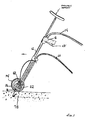
- Figure 1 illustrates the position of high pressure fluid jet hammer apparatus 10 at a predetermined angle from the vertical position (approximately 30 degrees) for applying an abrasive entrained waterjet to cut concrete, rock or other high strength material such as the concrete material 78 shown.
- Figure 2 illustrates high pressure fluid jet hammer apparatus 10 in the vertical position having a large biasing means such as the operator's weight overcoming biasing means 42 to position nozzle 16 and nozzle tip 82 vertically against the entrance to a cut pilot hole 84 within the concrete material 78 for applying the breaking mode of the novel method for breaking concrete according to the teachings of the invention.
- High pressure fluid jet hammer apparatus 10 is pushed to overcome first biasing means 42 and shroud 22 is buffeted against the concrete material 78.
- the tip 82 of nozzle 16 is compressed against the entrance 84 of pilot hole 82 by the bias force of the operator's weight, thus hindering the escape of fluid trapped inside the hole and enhancing the buildup of fluid pressure inside the hole to cause fracturing of the surrounding high strength material.
- Equipment system 100 consists of a suitable pump system 102 such as for example a triplex crankshift pump 104 capable of delivering water at a peak pressure of up to 20,000 psi in rotating communication with an engine or motor shown generally at 106 which may be for instance a diesel engine or an electric motor of suitable power rating and an abrasive feed and dispensing system 108.
- a suitable pump system 102 such as for example a triplex crankshift pump 104 capable of delivering water at a peak pressure of up to 20,000 psi in rotating communication with an engine or motor shown generally at 106 which may be for instance a diesel engine or an electric motor of suitable power rating and an abrasive feed and dispensing system 108.
- Both high pressure pump 102 and abrasive systems 108 are connected to high pressure flow jet hammer apparatus 10 through suitable high pressure fluid hose 112 and abrasive hose 114, respectively.
- Feed water, or other suitable fluid is fed to pump system 102 through filter 122 to remove particulates.
- the pressurized water is transported to water hammer apparatus 10 via high pressure hose 112 through by-pass valve 124 and pressure regulating means 126, by-pass valve 124 having a return connection through by-pass conduit 128 to pump system 102.
- Flexible hoses are currently available for system pressures of 20,000 psi, rigid metallic tubing being required if the system pressure is substantially higher than 20,000 psi.
- abrasives which could be sand, garnet, metallic slag or other industrial abrasives, are stored in a metallic abrasive tank 132.
- the abrasives are urged through abrasive hose 114 by means of the vacuum generated inside the nozzle of the high pressure hammer apparatus 10 by the high speed fluid jets (not shown but described in detail in the above-referenced, concurrently filed, co-pending application No. ........, reference as 28181
- This suction power can be as high as 20 to 30 inches of mercury and is powerful enough to bring heavy abrasives from a distant tank to the nozzle without the need for an external power supply, For excessively long distance or excessively heavy abrasives, however, an external supply of compressed air can be used.
- Valve means 134 is attached to abrasive tank 132 to adjust a desired flow rate.
- garnet abrasives can cut high strength concrete to a depth greater than 6 inches when the nozzle is moved along the surface of the pavement at a speed of about 6 inches per minute using the nominal orifice nozzle of this invention as described in the above referenced European patent application.
- the cut or slot using high pressure hammer apparatus 10 is typically very clean and substantially straight; spalling of concrete or aggregate is rarely encountered.
- the apparatus is held by an operator with one hand holding the water valve handle and operating the water valve actuating lever 28, while the other hand is holding the handle 64 and operating abrasive valve actuating lever 68.
- the shoulder support of the apparatus is butted against the operators shoulder or upper arm to thereby provide the downward bias discussed earlier.
- the abrasive fluid jet nozzle is positioned very close to the surface of the pavement, the stand off distance between the pavement and the nozzle is maintained by the support means 26 which may be for example support wheel 24 and is adjustable. It is desired that the water hammer apparatus is held and operated at an angle of about 70 to 80 degrees to the pavement surface and is advanced with the fluid jet leading the nozzle as shown in Figure 3.
- the high pressure fluid hammer apparatus of this invention can be used with the fluid jet trailing the nozzle or at a vertical position.
- the difference in cutting performance does not deviate much if the impingement angle is changed within a predetermined range of +/- 30°.
- the depth of cut can be adjusted by changing one of several system parameters, including system pressure, abrasive type and/or feed rate, nozzle stand off distance and nozzle traverse speed. This built in system flexibility is unmatched by any conventional material cutting methods.
- a patch of pavement In many pavement cutting operations, a patch of pavement must be removed to gain access to the soil and to buried systems such as cables and pipes.
- the apparatus of this invention can be used to make the perimeter cuts that delineate the area to be removed. The cuts may be through the entire thickness of the pavement such that the cut pads could be lifted with a suitable anchor system.
- a patch of concrete to be removed is outlined by perimeter cuts made with the abrasive entrained high pressure fluid jet hammer apparatus of the invention.
- To break this patch of concrete with the fluid hammer of the invention involves drilling partial depth holes by applying the abrasive water jet at a stationary position for a perscribed amount of time, such as 10 seconds or less, and by shutting off the abrasive supply after a hole of desired depth has been achieved.
- the cessation of abrasive flow stops the drilling operation as a water jet alone cannot drill concrete rapidly at water pressures of 20,000 psi or less.
- the operator would then use the receiving means for receiving the bias of his weight on the high pressure fluid jet hammer apparatus 10 to overcome the bias of the smaller first biasing means to insert the nozzle tip within the pilot hole as discussed earlier.
- the perimeter cuts should also be made to a partial depth.
- the reason is to avoid water jet penetration into the soil or underlying material to wash away pavement support.
- the water can be readily syphoned away with a suction system if it is kept on the surface of the pavement. This way only the water that was consumed in the breaking of the pavement would be lost into the subsoil.
- the efficiency of the breaking operation of the process of this invention is related to the force applied to the apparatus to keep the tip of the nozzle on top of the hole and how well the tip fits the hole. This explains why the tip of the nozzle cone should be convexly tapered externally.
- the amount of taper and the outside diameter of the nozzle cone are determined basically by the configuration of the waterjet bundle issued by the orifices.
- the significant advantages of this process as compared to existing methods of using jackhammers to break concrete are as follows: * Much higher productivity as each shot can remove substantially large amounts of concrete * No shock to underlying structures or to the operator * A single tool for cutting and breaking.
- the process of this invention involves the creation of pilot holes with abrasive-entrained waterjet, cutting slots with the same abrasive-entrained waterjet, and breaking concrete or rock with straight waterjet by generating high loop stresses inside the pilot holes.
- the suitable apparatus for applying this process could be the handheld device described herein; it could also be in the form of a mounted device.
Landscapes
- Engineering & Computer Science (AREA)
- Mechanical Engineering (AREA)
- Life Sciences & Earth Sciences (AREA)
- Forests & Forestry (AREA)
- Mining & Mineral Resources (AREA)
- Earth Drilling (AREA)
- Perforating, Stamping-Out Or Severing By Means Other Than Cutting (AREA)
- Processing Of Stones Or Stones Resemblance Materials (AREA)
Applications Claiming Priority (2)
| Application Number | Priority Date | Filing Date | Title |
|---|---|---|---|
| US79005185A | 1985-10-22 | 1985-10-22 | |
| US790051 | 1985-10-22 |
Publications (1)
| Publication Number | Publication Date |
|---|---|
| EP0221730A1 true EP0221730A1 (de) | 1987-05-13 |
Family
ID=25149501
Family Applications (1)
| Application Number | Title | Priority Date | Filing Date |
|---|---|---|---|
| EP86308228A Withdrawn EP0221730A1 (de) | 1985-10-22 | 1986-10-22 | Mit einem Schleifmittel versehenes Hochdruckflüssigkeitsstrahlgerät und dazugehörige Gebrauchsmethode |
Country Status (1)
| Country | Link |
|---|---|
| EP (1) | EP0221730A1 (de) |
Cited By (5)
| Publication number | Priority date | Publication date | Assignee | Title |
|---|---|---|---|---|
| US5016717A (en) * | 1989-03-14 | 1991-05-21 | Aqua-Vac Locators, Inc. | Vacuum excavator |
| DE19848437C2 (de) * | 1998-10-21 | 2002-09-19 | Doris Krug-Becker | Verfahren zum Sanieren schadhafter Verfugungen von Pflasterungen |
| WO2007066186A1 (en) * | 2005-12-08 | 2007-06-14 | Csir | Brittle material fracturing system |
| EP2420339A1 (de) * | 2010-08-16 | 2012-02-22 | Shouichi Shibuya | Schneidvorrichtung und Schneidverfahren |
| WO2017042686A1 (en) * | 2016-07-05 | 2017-03-16 | Universidad Tecnológica De Panamá | Pressurized-fluid abrasive cutting apparatus |
Citations (8)
| Publication number | Priority date | Publication date | Assignee | Title |
|---|---|---|---|---|
| DE1427781A1 (de) * | 1966-11-21 | 1969-01-30 | Woma Appbau W Maasberg & Co Gm | Schneidvorrichtung zum Schneiden und Bohren von Kunst- oder Natursteinen,insbesondere Beton |
| US3792907A (en) * | 1972-04-10 | 1974-02-19 | Inst Gas Technology | Process for removing asphalt topping from pavement substrate |
| US3796371A (en) * | 1972-05-19 | 1974-03-12 | Atlas Copco Ab | Jet piercing device |
| US3880354A (en) * | 1971-12-23 | 1975-04-29 | Chemetron Corp | Method and apparatus for controlling heat effect in metal cutting operations |
| US4074858A (en) * | 1976-11-01 | 1978-02-21 | Institute Of Gas Technology | High pressure pulsed water jet apparatus and process |
| GB1527063A (en) * | 1976-03-22 | 1978-10-04 | Franz N | Method and nozzle assembly for fluid jet penetration of a work material |
| GB1591250A (en) * | 1976-11-24 | 1981-06-17 | Atlas Copco Ab | Method and device for breaking a hard compact material |
| GB2095722A (en) * | 1981-03-31 | 1982-10-06 | Univ Exeter The | Forming an erosive jet |
-
1986
- 1986-10-22 EP EP86308228A patent/EP0221730A1/de not_active Withdrawn
Patent Citations (8)
| Publication number | Priority date | Publication date | Assignee | Title |
|---|---|---|---|---|
| DE1427781A1 (de) * | 1966-11-21 | 1969-01-30 | Woma Appbau W Maasberg & Co Gm | Schneidvorrichtung zum Schneiden und Bohren von Kunst- oder Natursteinen,insbesondere Beton |
| US3880354A (en) * | 1971-12-23 | 1975-04-29 | Chemetron Corp | Method and apparatus for controlling heat effect in metal cutting operations |
| US3792907A (en) * | 1972-04-10 | 1974-02-19 | Inst Gas Technology | Process for removing asphalt topping from pavement substrate |
| US3796371A (en) * | 1972-05-19 | 1974-03-12 | Atlas Copco Ab | Jet piercing device |
| GB1527063A (en) * | 1976-03-22 | 1978-10-04 | Franz N | Method and nozzle assembly for fluid jet penetration of a work material |
| US4074858A (en) * | 1976-11-01 | 1978-02-21 | Institute Of Gas Technology | High pressure pulsed water jet apparatus and process |
| GB1591250A (en) * | 1976-11-24 | 1981-06-17 | Atlas Copco Ab | Method and device for breaking a hard compact material |
| GB2095722A (en) * | 1981-03-31 | 1982-10-06 | Univ Exeter The | Forming an erosive jet |
Cited By (5)
| Publication number | Priority date | Publication date | Assignee | Title |
|---|---|---|---|---|
| US5016717A (en) * | 1989-03-14 | 1991-05-21 | Aqua-Vac Locators, Inc. | Vacuum excavator |
| DE19848437C2 (de) * | 1998-10-21 | 2002-09-19 | Doris Krug-Becker | Verfahren zum Sanieren schadhafter Verfugungen von Pflasterungen |
| WO2007066186A1 (en) * | 2005-12-08 | 2007-06-14 | Csir | Brittle material fracturing system |
| EP2420339A1 (de) * | 2010-08-16 | 2012-02-22 | Shouichi Shibuya | Schneidvorrichtung und Schneidverfahren |
| WO2017042686A1 (en) * | 2016-07-05 | 2017-03-16 | Universidad Tecnológica De Panamá | Pressurized-fluid abrasive cutting apparatus |
Similar Documents
| Publication | Publication Date | Title |
|---|---|---|
| US4111490A (en) | Method and apparatus for channel cutting of hard materials using high velocity fluid jets | |
| US5765965A (en) | Apparatus for in situ installation of underground containment barriers under contaminated lands | |
| US3427763A (en) | Method of treating solid surfaces | |
| US4673312A (en) | Method and apparatus for the underground installation of pipelines | |
| US5957624A (en) | Apparatus and method for in Situ installation of underground containment barriers under contaminated lands | |
| JPS611794A (ja) | 岩石を切断する方法および装置 | |
| WO1994019547A1 (en) | Method and apparatus for in situ installation of underground containment barriers under contaminated lands | |
| EP0653548A2 (de) | Verfahren zum Schneiden eines strukturellen Substrats mit einer Schleifpartikel enthaltenden Flüssigkeit | |
| EP0251660A1 (de) | Verfahren und Vorrichtung zum Ausheben von Boden und dergleichen | |
| US4474252A (en) | Method and apparatus for drilling generally horizontal bores | |
| CN113605899A (zh) | 一种基于水力冲击破碎与静力破碎的隧道开挖方法 | |
| CN114651109A (zh) | 一种用于钻进和将孔口支撑套管定位至爆破孔内的方法和设备 | |
| EP0221730A1 (de) | Mit einem Schleifmittel versehenes Hochdruckflüssigkeitsstrahlgerät und dazugehörige Gebrauchsmethode | |
| CN109356607B (zh) | 用于软硬地层的高水压伸缩式复合钻切方法 | |
| CN108915594B (zh) | 一种旋喷随钻定向导向装置 | |
| Abudayyeh et al. | Concrete bridge demolition methods and equipment | |
| EP0482019B1 (de) | Verfahren und gerät zum schneiden von erosiven materialien unter benutzung von hochdruckwasser | |
| JPH03169976A (ja) | 鉄筋コンクリート斫用偏角回転ウォータジェットガン | |
| CA2076217A1 (en) | Method of and an apparatus for material-removing working by means of multiple jets | |
| CN109162717B (zh) | 一种采矿、隧道工程水力掘进方法及其设备 | |
| JPH06100057B2 (ja) | トンネル掘削工法における粉塵防止方法 | |
| Hood et al. | A review of water-jet-assisted rock cutting | |
| TW294758B (en) | The digging construction method and device for tunnel | |
| KR960009279B1 (ko) | 해머드릴을 이용한 암반지층의 수평 타격 파괴식 터널 굴진 방법 및 그 장치 | |
| Manning | Removing concrete from bridges |
Legal Events
| Date | Code | Title | Description |
|---|---|---|---|
| PUAI | Public reference made under article 153(3) epc to a published international application that has entered the european phase |
Free format text: ORIGINAL CODE: 0009012 |
|
| AK | Designated contracting states |
Kind code of ref document: A1 Designated state(s): AT BE CH DE ES FR GB GR IT LI LU NL SE |
|
| STAA | Information on the status of an ep patent application or granted ep patent |
Free format text: STATUS: THE APPLICATION IS DEEMED TO BE WITHDRAWN |
|
| 18D | Application deemed to be withdrawn |
Effective date: 19871113 |
|
| RIN1 | Information on inventor provided before grant (corrected) |
Inventor name: YIE, GENE G. |