EP0221771A1 - Digitale Anzeigevorrichtung - Google Patents
Digitale Anzeigevorrichtung Download PDFInfo
- Publication number
- EP0221771A1 EP0221771A1 EP86308446A EP86308446A EP0221771A1 EP 0221771 A1 EP0221771 A1 EP 0221771A1 EP 86308446 A EP86308446 A EP 86308446A EP 86308446 A EP86308446 A EP 86308446A EP 0221771 A1 EP0221771 A1 EP 0221771A1
- Authority
- EP
- European Patent Office
- Prior art keywords
- display
- value
- comparator
- counter
- addends
- Prior art date
- Legal status (The legal status is an assumption and is not a legal conclusion. Google has not performed a legal analysis and makes no representation as to the accuracy of the status listed.)
- Granted
Links
- 238000005070 sampling Methods 0.000 claims abstract description 39
- 238000005259 measurement Methods 0.000 claims abstract description 22
- 230000004044 response Effects 0.000 claims abstract description 9
- 239000000446 fuel Substances 0.000 claims description 3
- 230000000717 retained effect Effects 0.000 claims description 3
- 230000002035 prolonged effect Effects 0.000 abstract description 2
- 230000001788 irregular Effects 0.000 description 3
- 238000009825 accumulation Methods 0.000 description 1
- 238000013459 approach Methods 0.000 description 1
- 230000006399 behavior Effects 0.000 description 1
- 238000010586 diagram Methods 0.000 description 1
- 230000010355 oscillation Effects 0.000 description 1
- 230000001052 transient effect Effects 0.000 description 1
Images

Classifications
-
- G—PHYSICS
- G01—MEASURING; TESTING
- G01R—MEASURING ELECTRIC VARIABLES; MEASURING MAGNETIC VARIABLES
- G01R13/00—Arrangements for displaying electric variables or waveforms
- G01R13/02—Arrangements for displaying electric variables or waveforms for displaying measured electric variables in digital form
-
- G—PHYSICS
- G01—MEASURING; TESTING
- G01D—MEASURING NOT SPECIALLY ADAPTED FOR A SPECIFIC VARIABLE; ARRANGEMENTS FOR MEASURING TWO OR MORE VARIABLES NOT COVERED IN A SINGLE OTHER SUBCLASS; TARIFF METERING APPARATUS; MEASURING OR TESTING NOT OTHERWISE PROVIDED FOR
- G01D7/00—Indicating measured values
-
- G—PHYSICS
- G01—MEASURING; TESTING
- G01R—MEASURING ELECTRIC VARIABLES; MEASURING MAGNETIC VARIABLES
- G01R13/00—Arrangements for displaying electric variables or waveforms
Definitions
- the present invention relates to an apparatus digitally detecting and displaying changes in a measurement value or more particularly a digital display apparatus of, for example, a fuel gage or voltmeter in which flickers of the displayed value are prevented.
- the one mentioned above is adapted therein such that a piece of sampling data output as a digital signal corresponding to a measurement value detected by a sensor at intervals of a predetermined period is compared with a piece of display data corresponding to a display value currently displayed on a display unit and the difference therebetween or a value corresponding to the difference is accumulated, the accumulated value is detected as to whether or not it has exceeded a predetermined range, and the display data is updated when the same has exceeded the predetermined range, and thus, irregular changes in the measurement value due to noise are absorbed and flickers of the displayed value are prevented.
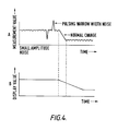
- the above mentioned prior art is of such a system that the differences between the sampling data and the display data or the values corresponding to the difference are accumulated as they are, and so, if the apparatus is provided with a slower response in order to prevent flickers due to irregular changes, or noise, other than normal changes, in the measurement value, i.e., such changes produced by small-amplitude fluctuations or narrow-width pulses as shown in Fig. 4A, there arises a problem that the response will become slower also to the real changes in the measurement value as shown in Fig. 4B. Therefore, the prior art system can be applied to a display apparatus for slowly changing measurement values, but the same, with its too slow a response, cannot be applied to a display apparatus for an abruptly changing measurement value.
- the present invention was made with the foregoing problem in view, and a primary object of the present invention is the provision of a digital display apparatus adapted such that, when the changes in the measurement value are of small-amplitude or pulsing narrow-width noise, its response will be made slower so that the flickers in the display value are prevented, and, when the changes in the measurement value are not of the noise but real changes, the response will be quickened so that a correct value is rapidly displayed, and therefore is applicable also to a display apparatus for a sharply changing measurement value.
- Fig. 1 shows an embodiment of the apparatus of the present invention applied to a voltmeter, wherein an analog signal as a measurement value detected by a voltage sensor 1 is converted by an A/D converter 2 into a digital signal at a predetermined sampling period.
- a latch circuit 3 retains the digital signal which is updated at the predetermined period and outputs the same as a piece of sampling data X to a first digital comparator 4.
- the first digital comparator 4 is connected with a digital display unit 5 arranged to include a decoder driver and serves to compare the data currently retained by a latch circuit 6, which is for retaining the display data Y corresponding to the value displayed on the display unit 5, with the above mentioned updated sampling data X from the latch circuit 3.
- an addend C is provided by an adder 7, and this addend C is accumulated in a first counter 8.
- a second comparator 9 compares a reference value A, which is predetermined and used for determining a display updating period to indicate the timing for updating the display, with the above mentioned accumulated addends in the first counter 8.
- a second counter 10 is for counting the number of times of the display updates made, for which display updating instructions have been output to the latch circuit 6 from the second comparator 9 when the value of the accumulated addends therein have exceeded the reference value A.
- a third comparator 11 is for comparing a preset reference value K for the number of times of display updates with the number of times of the display updates made counted by the second counter 10. According to the result of this comparison and to the result of the comparison made in the first comparator 4, the value of the above mentioned addend C is determined.
- a timer circuit 12 determines the set time T for measurement to detect whether or not the sampling data X is in the stabilized state, i.e., the state in which the difference W is smaller than a predetermined value, as well as clears the count of the display updates made in the second counter 10, so that a stabilized state of display updating is provided as soon as possible.
- a sign comparator 13 makes a successive comparison of the accumulated addends in the first counter 8 to detect a change of the sign of the addend input from the adder 7, i.e., a change of the sign of the difference between the sampling data X and the display data Y, and clears the second counter 10 when the change of the sign is detected.
- the difference between the sampling data X, updated at intervals of a predetermined sampling period of 1/128 second and retained by the latch circuit 3 and the display data Y, maintained in the latch circuit 6 and corresponding to the value currently displayed on the display unit 5, W ( X - Y), inclusive of its plus or minus sign, is detected by the first comparator 4.
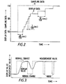
- the dotted line in Fig. 2 indicates the sampling data X
- the solid line indicates the display data Y, and it is assumed that these data X and Y were virtually equal and in a stabilized state at the start.
- This value C1 is supplied to the first counter 8.
- the sign comparator 13 successively compares the accumulated addends in the first counter 8 and detects if the plus or minus sign of the addend C from the adder 7 differs from the previous one, and if a change of the sign is detected, the same judges that a different state from the earlier changed state has been produced and clears the second counter 10. Such a change of the sign is regarded as an indication of a stabilized state.
- the first comparator 4 detects the difference W inclusive of a plus or minus sign and the adder 7 outputs the addend inclusive of the plus or minus sign to the first counter 8.
- the period for updating the display is changed depending on the difference between the sampling data X and the display data Y and the number of times the display updates made, and thereby, as shown in Fig. 2, the display updating period is made relatively long in the earlier stage when the sampling data X has just started to abruptly change, then the display updating period is made shorter so that the display data is rapidly brought closer to the sampling data X, and then, as the display data Y is brought close to the sampling data X, the display updating period is again prolonged.
- the display updating period is made relatively long in the earlier stage when the sampling data X has just started to abruptly change, then the display updating period is made shorter so that the display data is rapidly brought closer to the sampling data X, and then, as the display data Y is brought close to the sampling data X, the display updating period is again prolonged.
- the displayed value in the normal changed state, is made to change following the change in the measured value with the display updating period shortened and the response quickened, and in case of the noise having a large amplitude but a narrow width, the accumulation therefor is not made continuously, and hence, the display is not updated, i.e., the displayed value does not change following the change in the measured value, and therefore, the occurrence of flickers can be prevented.
- the above mentioned value of the addend C, reference vale A for display updating period, reference value K for the number of times of display updates, the set time T set in the timer circuit, etc. can be modified in various ways and established depending on the apparatus to which the invention is applied.
- the apparatus to which the invention is applicable may be fuel gages, and so on, in addition to the above described voltmeter.
Landscapes
- Physics & Mathematics (AREA)
- General Physics & Mathematics (AREA)
- Measurement Of Current Or Voltage (AREA)
- Measurement Of Levels Of Liquids Or Fluent Solid Materials (AREA)
- Indicating Measured Values (AREA)
- Control Of Indicators Other Than Cathode Ray Tubes (AREA)
- Circuits Of Receivers In General (AREA)
Priority Applications (1)
| Application Number | Priority Date | Filing Date | Title |
|---|---|---|---|
| AT86308446T ATE59914T1 (de) | 1985-10-29 | 1986-10-29 | Digitale anzeigevorrichtung. |
Applications Claiming Priority (2)
| Application Number | Priority Date | Filing Date | Title |
|---|---|---|---|
| JP243385/85 | 1985-10-29 | ||
| JP60243385A JPS62102117A (ja) | 1985-10-29 | 1985-10-29 | デジタル表示装置 |
Publications (2)
| Publication Number | Publication Date |
|---|---|
| EP0221771A1 true EP0221771A1 (de) | 1987-05-13 |
| EP0221771B1 EP0221771B1 (de) | 1991-01-09 |
Family
ID=17103066
Family Applications (1)
| Application Number | Title | Priority Date | Filing Date |
|---|---|---|---|
| EP86308446A Expired - Lifetime EP0221771B1 (de) | 1985-10-29 | 1986-10-29 | Digitale Anzeigevorrichtung |
Country Status (6)
| Country | Link |
|---|---|
| US (1) | US4736185A (de) |
| EP (1) | EP0221771B1 (de) |
| JP (1) | JPS62102117A (de) |
| AT (1) | ATE59914T1 (de) |
| CA (1) | CA1260639A (de) |
| DE (1) | DE3676787D1 (de) |
Families Citing this family (3)
| Publication number | Priority date | Publication date | Assignee | Title |
|---|---|---|---|---|
| US6097399A (en) * | 1998-01-16 | 2000-08-01 | Honeywell Inc. | Display of visual data utilizing data aggregation |
| DE102011081901A1 (de) * | 2011-08-31 | 2013-02-28 | Bayerische Motoren Werke Aktiengesellschaft | Verfahren zum Betreiben einer Steuervorrichtung für ein Display eines Fahrzeugs und Steuervorrichtung |
| US10417306B1 (en) * | 2013-01-03 | 2019-09-17 | Amazon Technologies, Inc. | Determining load completion of dynamically updated content |
Citations (1)
| Publication number | Priority date | Publication date | Assignee | Title |
|---|---|---|---|---|
| US4509044A (en) * | 1981-05-13 | 1985-04-02 | Nippon Seiki Kabushiki Kaisha | Device which accurately displays changes in a quantity to be measured |
Family Cites Families (1)
| Publication number | Priority date | Publication date | Assignee | Title |
|---|---|---|---|---|
| US4521885A (en) * | 1983-01-05 | 1985-06-04 | Towmotor Corporation | Diagnostic display apparatus |
-
1985
- 1985-10-29 JP JP60243385A patent/JPS62102117A/ja active Granted
-
1986
- 1986-10-29 US US06/924,629 patent/US4736185A/en not_active Expired - Fee Related
- 1986-10-29 AT AT86308446T patent/ATE59914T1/de not_active IP Right Cessation
- 1986-10-29 DE DE8686308446T patent/DE3676787D1/de not_active Expired - Lifetime
- 1986-10-29 EP EP86308446A patent/EP0221771B1/de not_active Expired - Lifetime
- 1986-10-31 CA CA000521919A patent/CA1260639A/en not_active Expired
Patent Citations (1)
| Publication number | Priority date | Publication date | Assignee | Title |
|---|---|---|---|---|
| US4509044A (en) * | 1981-05-13 | 1985-04-02 | Nippon Seiki Kabushiki Kaisha | Device which accurately displays changes in a quantity to be measured |
Also Published As
| Publication number | Publication date |
|---|---|
| JPS62102117A (ja) | 1987-05-12 |
| DE3676787D1 (de) | 1991-02-14 |
| CA1260639A (en) | 1989-09-26 |
| EP0221771B1 (de) | 1991-01-09 |
| JPH0341772B2 (de) | 1991-06-25 |
| US4736185A (en) | 1988-04-05 |
| ATE59914T1 (de) | 1991-01-15 |
Similar Documents
| Publication | Publication Date | Title |
|---|---|---|
| US5054315A (en) | Coding of the value of several quantities measured in a tire | |
| US4509044A (en) | Device which accurately displays changes in a quantity to be measured | |
| US4858161A (en) | Method for the automatic calibration of a high-resolution electronic balance | |
| US4380733A (en) | Frequency and speed display device | |
| JPH025272B2 (de) | ||
| EP0146640B1 (de) | Schaltung zur periodendauermessung | |
| EP0633455A1 (de) | Magnetisch-induktiver Durchflussmesser | |
| KR920022636A (ko) | 회전 펄스 인코더를 사용하여 극히 저속의 범위에서 전기 모터의 속도를 제어하기 위한 시스템 및 방법 | |
| EP0221771B1 (de) | Digitale Anzeigevorrichtung | |
| EP0806641A1 (de) | Elektronisches medizinalthermometer | |
| US4375601A (en) | Signal stability recognition | |
| US6219624B1 (en) | Synchronous timer vehicle speed measurement | |
| US5525899A (en) | Physical quantity change detection device which detects change by detecting a phase difference between two pulses | |
| EP0164710B1 (de) | Phasenverriegeltes Abtastverfahren während der Messung periodischer Grössen, sowie Vorrichtung zur Durchführung dieses Verfahrens | |
| EP0381217B1 (de) | Signal-Pegel-Erkennungsschaltkreise | |
| JPH0340326B2 (de) | ||
| JP3098759B2 (ja) | 歩数計 | |
| SU1631446A1 (ru) | Автоматизированный осциллограф | |
| US4972139A (en) | Method for increasing the resolution of measurements taken using a counter-timer | |
| JPH0460468A (ja) | パルス位置計測型計器駆動回路 | |
| JPS60182354A (ja) | インジエクタ駆動パルス幅の測定装置 | |
| JP2698214B2 (ja) | アナログ入力コントローラ | |
| US4984469A (en) | Amplitude measurement device for viscoelasticity analysis | |
| JPH07120335A (ja) | トルク検知装置 | |
| JPH06174769A (ja) | 信号のパルスデューティー比を検出する装置 |
Legal Events
| Date | Code | Title | Description |
|---|---|---|---|
| PUAI | Public reference made under article 153(3) epc to a published international application that has entered the european phase |
Free format text: ORIGINAL CODE: 0009012 |
|
| AK | Designated contracting states |
Kind code of ref document: A1 Designated state(s): AT BE CH DE FR GB IT LI LU NL SE |
|
| 17P | Request for examination filed |
Effective date: 19871016 |
|
| 17Q | First examination report despatched |
Effective date: 19890725 |
|
| GRAA | (expected) grant |
Free format text: ORIGINAL CODE: 0009210 |
|
| AK | Designated contracting states |
Kind code of ref document: B1 Designated state(s): AT BE CH DE FR GB IT LI LU NL SE |
|
| PG25 | Lapsed in a contracting state [announced via postgrant information from national office to epo] |
Ref country code: NL Effective date: 19910109 Ref country code: LI Effective date: 19910109 Ref country code: CH Effective date: 19910109 Ref country code: BE Effective date: 19910109 Ref country code: AT Effective date: 19910109 |
|
| REF | Corresponds to: |
Ref document number: 59914 Country of ref document: AT Date of ref document: 19910115 Kind code of ref document: T |
|
| REF | Corresponds to: |
Ref document number: 3676787 Country of ref document: DE Date of ref document: 19910214 |
|
| ET | Fr: translation filed | ||
| ITF | It: translation for a ep patent filed | ||
| REG | Reference to a national code |
Ref country code: CH Ref legal event code: PL |
|
| NLV1 | Nl: lapsed or annulled due to failure to fulfill the requirements of art. 29p and 29m of the patents act | ||
| PGFP | Annual fee paid to national office [announced via postgrant information from national office to epo] |
Ref country code: SE Payment date: 19911028 Year of fee payment: 6 |
|
| PG25 | Lapsed in a contracting state [announced via postgrant information from national office to epo] |
Ref country code: LU Free format text: LAPSE BECAUSE OF NON-PAYMENT OF DUE FEES Effective date: 19911031 |
|
| PLBE | No opposition filed within time limit |
Free format text: ORIGINAL CODE: 0009261 |
|
| STAA | Information on the status of an ep patent application or granted ep patent |
Free format text: STATUS: NO OPPOSITION FILED WITHIN TIME LIMIT |
|
| 26N | No opposition filed | ||
| PGFP | Annual fee paid to national office [announced via postgrant information from national office to epo] |
Ref country code: FR Payment date: 19921023 Year of fee payment: 7 |
|
| PG25 | Lapsed in a contracting state [announced via postgrant information from national office to epo] |
Ref country code: SE Effective date: 19921030 |
|
| PG25 | Lapsed in a contracting state [announced via postgrant information from national office to epo] |
Ref country code: FR Effective date: 19940630 |
|
| REG | Reference to a national code |
Ref country code: FR Ref legal event code: ST |
|
| EUG | Se: european patent has lapsed |
Ref document number: 86308446.3 Effective date: 19930510 |
|
| PGFP | Annual fee paid to national office [announced via postgrant information from national office to epo] |
Ref country code: GB Payment date: 19981030 Year of fee payment: 13 |
|
| PGFP | Annual fee paid to national office [announced via postgrant information from national office to epo] |
Ref country code: DE Payment date: 19981106 Year of fee payment: 13 |
|
| PG25 | Lapsed in a contracting state [announced via postgrant information from national office to epo] |
Ref country code: GB Free format text: LAPSE BECAUSE OF NON-PAYMENT OF DUE FEES Effective date: 19991029 |
|
| GBPC | Gb: european patent ceased through non-payment of renewal fee |
Effective date: 19991029 |
|
| PG25 | Lapsed in a contracting state [announced via postgrant information from national office to epo] |
Ref country code: DE Free format text: LAPSE BECAUSE OF NON-PAYMENT OF DUE FEES Effective date: 20000801 |
|
| PG25 | Lapsed in a contracting state [announced via postgrant information from national office to epo] |
Ref country code: IT Free format text: LAPSE BECAUSE OF NON-PAYMENT OF DUE FEES;WARNING: LAPSES OF ITALIAN PATENTS WITH EFFECTIVE DATE BEFORE 2007 MAY HAVE OCCURRED AT ANY TIME BEFORE 2007. THE CORRECT EFFECTIVE DATE MAY BE DIFFERENT FROM THE ONE RECORDED. Effective date: 20051029 |