EP0221860B1 - Multi-component tubular structure for underwater conveyance of fluids - Google Patents
Multi-component tubular structure for underwater conveyance of fluids Download PDFInfo
- Publication number
- EP0221860B1 EP0221860B1 EP86830305A EP86830305A EP0221860B1 EP 0221860 B1 EP0221860 B1 EP 0221860B1 EP 86830305 A EP86830305 A EP 86830305A EP 86830305 A EP86830305 A EP 86830305A EP 0221860 B1 EP0221860 B1 EP 0221860B1
- Authority
- EP
- European Patent Office
- Prior art keywords
- pipe
- pipeline
- tubular structure
- rings
- fluids
- Prior art date
- Legal status (The legal status is an assumption and is not a legal conclusion. Google has not performed a legal analysis and makes no representation as to the accuracy of the status listed.)
- Expired
Links
- 239000012530 fluid Substances 0.000 title claims description 3
- 239000004033 plastic Substances 0.000 claims description 15
- 229920003023 plastic Polymers 0.000 claims description 15
- 239000004567 concrete Substances 0.000 claims description 6
- 229910000831 Steel Inorganic materials 0.000 claims description 5
- 239000010959 steel Substances 0.000 claims description 5
- 239000000463 material Substances 0.000 claims description 4
- 239000004698 Polyethylene Substances 0.000 claims description 2
- -1 polyethylene Polymers 0.000 claims description 2
- 229920000573 polyethylene Polymers 0.000 claims description 2
- 238000000034 method Methods 0.000 description 9
- XLYOFNOQVPJJNP-UHFFFAOYSA-N water Substances O XLYOFNOQVPJJNP-UHFFFAOYSA-N 0.000 description 9
- 239000011248 coating agent Substances 0.000 description 3
- 238000000576 coating method Methods 0.000 description 3
- 238000005452 bending Methods 0.000 description 2
- 230000007797 corrosion Effects 0.000 description 2
- 238000005260 corrosion Methods 0.000 description 2
- 238000005304 joining Methods 0.000 description 2
- 238000003466 welding Methods 0.000 description 2
- 235000012206 bottled water Nutrition 0.000 description 1
- 150000001875 compounds Chemical class 0.000 description 1
- 230000008878 coupling Effects 0.000 description 1
- 238000010168 coupling process Methods 0.000 description 1
- 238000005859 coupling reaction Methods 0.000 description 1
- 238000013461 design Methods 0.000 description 1
- 238000011161 development Methods 0.000 description 1
- 239000003651 drinking water Substances 0.000 description 1
- 239000003365 glass fiber Substances 0.000 description 1
- 230000001788 irregular Effects 0.000 description 1
- 238000012423 maintenance Methods 0.000 description 1
- 230000000063 preceeding effect Effects 0.000 description 1
- 239000011150 reinforced concrete Substances 0.000 description 1
- 238000005096 rolling process Methods 0.000 description 1
- 238000004513 sizing Methods 0.000 description 1
- 238000012360 testing method Methods 0.000 description 1
Images
Classifications
-
- F—MECHANICAL ENGINEERING; LIGHTING; HEATING; WEAPONS; BLASTING
- F16—ENGINEERING ELEMENTS AND UNITS; GENERAL MEASURES FOR PRODUCING AND MAINTAINING EFFECTIVE FUNCTIONING OF MACHINES OR INSTALLATIONS; THERMAL INSULATION IN GENERAL
- F16L—PIPES; JOINTS OR FITTINGS FOR PIPES; SUPPORTS FOR PIPES, CABLES OR PROTECTIVE TUBING; MEANS FOR THERMAL INSULATION IN GENERAL
- F16L1/00—Laying or reclaiming pipes; Repairing or joining pipes on or under water
- F16L1/12—Laying or reclaiming pipes on or under water
- F16L1/16—Laying or reclaiming pipes on or under water on the bottom
- F16L1/165—Laying or reclaiming pipes on or under water on the bottom by towing the pipe on or near the bottom
-
- F—MECHANICAL ENGINEERING; LIGHTING; HEATING; WEAPONS; BLASTING
- F16—ENGINEERING ELEMENTS AND UNITS; GENERAL MEASURES FOR PRODUCING AND MAINTAINING EFFECTIVE FUNCTIONING OF MACHINES OR INSTALLATIONS; THERMAL INSULATION IN GENERAL
- F16L—PIPES; JOINTS OR FITTINGS FOR PIPES; SUPPORTS FOR PIPES, CABLES OR PROTECTIVE TUBING; MEANS FOR THERMAL INSULATION IN GENERAL
- F16L9/00—Rigid pipes
- F16L9/12—Rigid pipes of plastics with or without reinforcement
Definitions
- pipelines for conveyance of fluids are widespread.
- pipelines for oil or for potable water are laid on, or buried in, the sea floor or across lakes and rivers, and long submarine outfalls are used for the discharge of treated or untreated effluents offshore.
- the pipes employed for such purposes should conform, so far as possible, to various requirements: resistance to external and internal corrosion; sufficient flexibility to fit the bottom morphology with minimal dredging work; high immersed weight, to give the installed pipe good stability against the action of waves and currents, and to prevent the floating of the pipeline.
- Such floating may be occasioned by the accidental intrusion of air into pipelines designed for conveying water; however, floating is avoided if the overall immersed weight of the pipe is so high that there is negative buoyancy even when the pipe is empty of water. For pipelines buried in mud, the immersed weight needs to exceed the weight of the mud displaced.
- an underwater pipeline should be:
- a uniform and reasonably smooth surface is also required when conventional underwater pipe-burying machines are to be used. Such machines are driven (on wheels) slang the pipeline to be buried, so that significant protrusions from the outer wall cannot be tolerated.
- the pipeline should allow the use of a reliable and relatively cheap method of laying.
- the "bottom pull" method (which is often used for concrete-coated steel pipes) is of a particular importance.
- the pipeline is constructed near the shoreline, single pipes being joined in “strings” and successive strings joined together ashore as the launching of the pipeline progresses.
- the pipeline is supported by a series of rubber wheels, which allow the forward movement to proceed with minimal resistance.
- the immersed pipeline moves forward (being pulled towards a barge equipped with a winch), sliding overthe bed of the sea, river or lake on which it is to be laid.
- the effective weight of the immersed pipeline is kept sufficiently small to reduce the frictional resistance on the bed, so avoiding the requirement of excessive pulling force. This is achieved, for instance, during the pulling of steel pipes by keeping them empty of water and using a concrete coating of suitable thickness.
- the requirements of the weighted pipeline to be laid by this method thus include:
- ballast weight devices are firmly fastened to the plastic pipe in a more simple, fast and effective way (therefore stemming from nearly opposite concepts with regard to the tubular structure here described here: to begin, ballast weight devices must not be fastened to the pipe and must not be spaced).
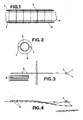
- the above mentioned tubular structure consists of:
- rings may also be cast, using the pipe as a former, with the help of soft spacing collars made of such material as rubber or polyethylene.
- the rings are designed to give an over-all immersed weight (when the pipe is empty of water) suitable for the "bottom pull" as described earlier.
- ribs protruding from the outer wall of the pipe at suitable intervals. These ribs may conveniently be constructed at the pipe joints.
- Each string is made by joining together individual units of the tubular structure described above. This joining may be by welding - both of the ends of the plastic pipes and of the rods so as to produce jointless pulling rods.
- the strings so constructed from pipes, rings and rods, are supported by a suitable structure of beams which allow easy rolling of the strings and the loading onto the rubber wheels (e in Figs 3 and 4).
- the laying proceeds by pulling with a winch (f in Figs 3 and 4) mounted on a well-anchored barge offshore.
- the pipeline (containing no water) slides forward from the rollers and along the bed.
- Coupling between successive strings can be effected by welding the ends (as already mentioned) or by other methods; in any case, the coating of the pipe can be completed, around the joints, by means of tubular moulds and a cast of quick-setting compound (e.g., quick-setting concrete).
- quick-setting compound e.g., quick-setting concrete
- the pipeline When the pull of the whole pipeline has been completed, the pipeline is filled with water and (if necessary) is buried in the bed by means of pipe-burying machines which, by virtue of the design of the pipeline, can thus be used for plastic pipes essentially because of the uniformity of the outer wall and the adequate weight.
- Such a tubular structure shows the main advantages of plastic pipes (regarding corrosion resistance, small loss of hydraulic head, adaptability to bed morphology) together with those advantages formerly confined to non-plastic pipes: strong mechanical protection all over the outer wall; high immersed weight - sufficient to keep the pipe in the bed even if air is blown inside to fill the whole pipe (as may be required for maintenance); and ballasting load distributed evenly along the pipe - instead of the concentrated loads induced by spaced weights which may cause irregular settling of the pipeline and consequent dangerous stressing.
- tubular structure herein described make it suitable for other laying techniques (such as the "lay barge” and “controlled floating” methods) owing to its high tensile strength, the ease of control of the immersed weight, the small bending radius typical of plastic pipes, and the quasi-uniform outer wall.
Landscapes
- Engineering & Computer Science (AREA)
- General Engineering & Computer Science (AREA)
- Mechanical Engineering (AREA)
- Rigid Pipes And Flexible Pipes (AREA)
Applications Claiming Priority (2)
| Application Number | Priority Date | Filing Date | Title |
|---|---|---|---|
| IT8582820A IT1214959B (it) | 1985-10-29 | 1985-10-29 | Struttura tubolare composta per convogliamento subacqueo di fluidi. |
| IT8282085 | 1985-10-29 |
Publications (2)
| Publication Number | Publication Date |
|---|---|
| EP0221860A1 EP0221860A1 (en) | 1987-05-13 |
| EP0221860B1 true EP0221860B1 (en) | 1990-10-17 |
Family
ID=11319522
Family Applications (1)
| Application Number | Title | Priority Date | Filing Date |
|---|---|---|---|
| EP86830305A Expired EP0221860B1 (en) | 1985-10-29 | 1986-10-24 | Multi-component tubular structure for underwater conveyance of fluids |
Country Status (4)
| Country | Link |
|---|---|
| US (1) | US4739800A (it) |
| EP (1) | EP0221860B1 (it) |
| DE (1) | DE3674983D1 (it) |
| IT (1) | IT1214959B (it) |
Cited By (1)
| Publication number | Priority date | Publication date | Assignee | Title |
|---|---|---|---|---|
| DE102013112914A1 (de) * | 2013-11-22 | 2015-05-28 | Egeplast International Gmbh | Kunststoffprofil, insbesondere Kunststoffrohr |
Families Citing this family (14)
| Publication number | Priority date | Publication date | Assignee | Title |
|---|---|---|---|---|
| GB2206665A (en) * | 1987-07-01 | 1989-01-11 | Stanton Plc | Assembly and installation of pipes |
| US5133163A (en) * | 1987-09-17 | 1992-07-28 | Christensen Bruce A | Conduit containing construction block |
| US5340508A (en) * | 1992-11-23 | 1994-08-23 | Clean-Flo Laboratories, Inc. | Aeration system and method |
| US5439323A (en) * | 1993-07-09 | 1995-08-08 | Westinghouse Electric Corporation | Rod and shell composite riser |
| NL9400798A (nl) * | 1994-05-16 | 1996-01-02 | Groot Nijkerk Maschf B V De | Leidingsysteem. |
| FR2728598B1 (fr) * | 1994-12-23 | 1997-03-14 | Pierre Becker | Procede et dispositif de protection d'ouvrages sous-marins de forme allongee et positionnes au fond de la mer |
| DE19509116C2 (de) * | 1995-03-16 | 2000-01-05 | Deutsch Zentr Luft & Raumfahrt | Flexible Struktur |
| WO1998021415A1 (en) * | 1996-11-12 | 1998-05-22 | H.B. Zachry Company | Precast, modular spar system |
| JP2002523321A (ja) * | 1998-08-20 | 2002-07-30 | ボジー ヴェルノ ビーブイ | 細長く伸びた管またはケーブルの貯蔵および(または)輸送方法および手段 |
| FR2784734B1 (fr) * | 1998-10-14 | 2000-11-24 | Novoplastic Sa | Ensemble pour la construction d'un reseau de transport subaquatique de fluide, d'energie, ou de signaux |
| US6536364B1 (en) * | 1999-06-29 | 2003-03-25 | Mcdermott David Ken | Mooring apparatus |
| FR2857690B1 (fr) * | 2003-07-15 | 2005-08-26 | Inst Francais Du Petrole | Systeme de forage en mer comprenant une colonne montante haute pression |
| EP2161488A1 (en) * | 2008-09-09 | 2010-03-10 | Heerema Fabrication Group B.V. | A pipe section for use in a submerged pipeline system, the submerged pipeline system and the use thereof |
| US20260055827A1 (en) * | 2024-06-20 | 2026-02-26 | Longitude 123, Inc. | Ballast weight lock |
Family Cites Families (9)
| Publication number | Priority date | Publication date | Assignee | Title |
|---|---|---|---|---|
| US2419053A (en) * | 1942-07-03 | 1947-04-15 | Okonite Callender Cable Co Inc | Buoyant electric cable |
| FR1261508A (fr) * | 1960-06-23 | 1961-05-19 | Clifford Hartley Patents Ltd | Canalisations pour gaz ou liquides naturels et procédé et appareil pour sa fabrication |
| US3162214A (en) * | 1963-01-16 | 1964-12-22 | American Optical Corp | Flexible tubular structures |
| US3290429A (en) * | 1964-08-04 | 1966-12-06 | Bell Telephone Labor Inc | Armored electric line |
| US3267969A (en) * | 1964-08-17 | 1966-08-23 | James B Mallard | Reenforced weighted pipe |
| DE1525500B1 (de) * | 1966-03-22 | 1970-01-29 | Josef Riepl Bau Unternehmung | Aus mehreren Betonrohren zusammengesetzter zur gemeinsamen Verlegung unter bzw. im Wasser bestimmter Rohrleitungsabschnitt,insbesondere fuer Kanalisationsleitungen |
| FR2137379B2 (it) * | 1971-05-14 | 1973-05-25 | Loribon Gerard | |
| DK370977A (da) * | 1977-08-19 | 1979-02-20 | Nordiske Kabel Og Traadfbrikke | Undervandsledning saasom et kabel eller roer samt vaegtbelastningsanordning til anvendelse paa saadanne ledninger |
| NL8102122A (nl) * | 1981-04-29 | 1982-11-16 | Hollandsche Betongroep Nv | Leiding voor het transporteren van een vloeistof naar en/of van de wal naar een ver weg onder water gelegen punt, zoals een waterleiding voor een inrichting voor het winnen van energie uit temperatuurverschil. |
-
1985
- 1985-10-29 IT IT8582820A patent/IT1214959B/it active
-
1986
- 1986-10-24 EP EP86830305A patent/EP0221860B1/en not_active Expired
- 1986-10-24 DE DE8686830305T patent/DE3674983D1/de not_active Expired - Fee Related
- 1986-10-29 US US06/924,449 patent/US4739800A/en not_active Expired - Fee Related
Cited By (1)
| Publication number | Priority date | Publication date | Assignee | Title |
|---|---|---|---|---|
| DE102013112914A1 (de) * | 2013-11-22 | 2015-05-28 | Egeplast International Gmbh | Kunststoffprofil, insbesondere Kunststoffrohr |
Also Published As
| Publication number | Publication date |
|---|---|
| US4739800A (en) | 1988-04-26 |
| IT8582820A0 (it) | 1985-10-29 |
| DE3674983D1 (de) | 1990-11-22 |
| IT1214959B (it) | 1990-01-31 |
| EP0221860A1 (en) | 1987-05-13 |
Similar Documents
| Publication | Publication Date | Title |
|---|---|---|
| US4739800A (en) | Multi-component tubular structure for underwater conveyance of fluids | |
| US4242010A (en) | Method and means for protecting a sea bottom surface and an installation on same | |
| US2910835A (en) | Pipe laying apparatus and method | |
| US3911688A (en) | Pipe apparatus for the collection of petroleum from deep water wells | |
| US4102137A (en) | Coating and protective device | |
| US6199595B1 (en) | Insulated marine pipe apparatus and method of installation | |
| US6357966B1 (en) | Ballasting method and apparatus for the installation of synthetic underwater pipelines | |
| US3849997A (en) | Submarine pipelines | |
| US4110994A (en) | Marine pipeline | |
| US3724224A (en) | Method for installing double-walled pipelines | |
| US3425453A (en) | Ocean pipeline system | |
| US3788084A (en) | Recovery of marine pipelines | |
| US3583169A (en) | Submarine pipeline laying | |
| EP1022501A1 (en) | Marine pipeline installation method and apparatus | |
| CN86108852A (zh) | 大型水下管线、从陆地下水的方法 | |
| US3698348A (en) | Method and apparatus for subsurface towing of flowlines | |
| AU2005299054B2 (en) | Process, system and equipment for the towing of underwater pipelines | |
| US3479831A (en) | Method and system for laying pipe under water | |
| US4421437A (en) | Corrugated buckle arrestor | |
| US3702539A (en) | Method and apparatus for installing risers | |
| US3940942A (en) | Submarine pipelines | |
| US3656310A (en) | Method for laying submarine pipelines | |
| Akten et al. | On the design and construction of Statpipe pipeline system | |
| RU2065117C1 (ru) | Устройство для удержания подводного трубопровода (варианты) | |
| KR20050032066A (ko) | 부설선 없이 심해 파이트라인 부설방법 |
Legal Events
| Date | Code | Title | Description |
|---|---|---|---|
| PUAI | Public reference made under article 153(3) epc to a published international application that has entered the european phase |
Free format text: ORIGINAL CODE: 0009012 |
|
| AK | Designated contracting states |
Kind code of ref document: A1 Designated state(s): DE ES FR GB NL SE |
|
| 17P | Request for examination filed |
Effective date: 19870811 |
|
| 17Q | First examination report despatched |
Effective date: 19880105 |
|
| GRAA | (expected) grant |
Free format text: ORIGINAL CODE: 0009210 |
|
| AK | Designated contracting states |
Kind code of ref document: B1 Designated state(s): DE ES FR GB NL SE |
|
| PG25 | Lapsed in a contracting state [announced via postgrant information from national office to epo] |
Ref country code: SE Effective date: 19901017 Ref country code: NL Effective date: 19901017 |
|
| REF | Corresponds to: |
Ref document number: 3674983 Country of ref document: DE Date of ref document: 19901122 |
|
| PG25 | Lapsed in a contracting state [announced via postgrant information from national office to epo] |
Ref country code: ES Free format text: LAPSE BECAUSE OF FAILURE TO SUBMIT A TRANSLATION OF THE DESCRIPTION OR TO PAY THE FEE WITHIN THE PRESCRIBED TIME-LIMIT Effective date: 19910128 |
|
| ET | Fr: translation filed | ||
| NLV1 | Nl: lapsed or annulled due to failure to fulfill the requirements of art. 29p and 29m of the patents act | ||
| PLBE | No opposition filed within time limit |
Free format text: ORIGINAL CODE: 0009261 |
|
| STAA | Information on the status of an ep patent application or granted ep patent |
Free format text: STATUS: NO OPPOSITION FILED WITHIN TIME LIMIT |
|
| 26N | No opposition filed | ||
| PGFP | Annual fee paid to national office [announced via postgrant information from national office to epo] |
Ref country code: GB Payment date: 19931025 Year of fee payment: 8 |
|
| PGFP | Annual fee paid to national office [announced via postgrant information from national office to epo] |
Ref country code: FR Payment date: 19931029 Year of fee payment: 8 |
|
| PGFP | Annual fee paid to national office [announced via postgrant information from national office to epo] |
Ref country code: DE Payment date: 19931230 Year of fee payment: 8 |
|
| PG25 | Lapsed in a contracting state [announced via postgrant information from national office to epo] |
Ref country code: GB Effective date: 19941024 |
|
| GBPC | Gb: european patent ceased through non-payment of renewal fee |
Effective date: 19941024 |
|
| PG25 | Lapsed in a contracting state [announced via postgrant information from national office to epo] |
Ref country code: FR Effective date: 19950630 |
|
| PG25 | Lapsed in a contracting state [announced via postgrant information from national office to epo] |
Ref country code: DE Effective date: 19950701 |
|
| REG | Reference to a national code |
Ref country code: FR Ref legal event code: ST |