EP0221867A2 - Verfahren zur Herstellung einer Pumpenstange durch Verbinden von Pumpgestänge für das Aufziehen von Öl und Pumpgestänge, Kupplungselemente und ein Werkzeug zum Verrichten dieses Verfahrens - Google Patents
Verfahren zur Herstellung einer Pumpenstange durch Verbinden von Pumpgestänge für das Aufziehen von Öl und Pumpgestänge, Kupplungselemente und ein Werkzeug zum Verrichten dieses Verfahrens Download PDFInfo
- Publication number
- EP0221867A2 EP0221867A2 EP86850321A EP86850321A EP0221867A2 EP 0221867 A2 EP0221867 A2 EP 0221867A2 EP 86850321 A EP86850321 A EP 86850321A EP 86850321 A EP86850321 A EP 86850321A EP 0221867 A2 EP0221867 A2 EP 0221867A2
- Authority
- EP
- European Patent Office
- Prior art keywords
- sucker rods
- sleeve
- rod
- outer sleeve
- oil
- Prior art date
- Legal status (The legal status is an assumption and is not a legal conclusion. Google has not performed a legal analysis and makes no representation as to the accuracy of the status listed.)
- Withdrawn
Links
Images

Classifications
-
- E—FIXED CONSTRUCTIONS
- E21—EARTH OR ROCK DRILLING; MINING
- E21B—EARTH OR ROCK DRILLING; OBTAINING OIL, GAS, WATER, SOLUBLE OR MELTABLE MATERIALS OR A SLURRY OF MINERALS FROM WELLS
- E21B17/00—Drilling rods or pipes; Flexible drill strings; Kellies; Drill collars; Sucker rods; Cables; Casings; Tubings
- E21B17/02—Couplings; joints
- E21B17/04—Couplings; joints between rod or the like and bit or between rod and rod or the like
-
- B—PERFORMING OPERATIONS; TRANSPORTING
- B23—MACHINE TOOLS; METAL-WORKING NOT OTHERWISE PROVIDED FOR
- B23P—METAL-WORKING NOT OTHERWISE PROVIDED FOR; COMBINED OPERATIONS; UNIVERSAL MACHINE TOOLS
- B23P11/00—Connecting or disconnecting metal parts or objects by metal-working techniques not otherwise provided for
-
- B—PERFORMING OPERATIONS; TRANSPORTING
- B25—HAND TOOLS; PORTABLE POWER-DRIVEN TOOLS; MANIPULATORS
- B25B—TOOLS OR BENCH DEVICES NOT OTHERWISE PROVIDED FOR, FOR FASTENING, CONNECTING, DISENGAGING, OR HOLDING
- B25B27/00—Hand tools, specially adapted for fitting together or separating parts or objects whether or not involving some deformation, not otherwise provided for
- B25B27/02—Hand tools, specially adapted for fitting together or separating parts or objects whether or not involving some deformation, not otherwise provided for for connecting objects by press fit or detaching same
- B25B27/026—Hand tools, specially adapted for fitting together or separating parts or objects whether or not involving some deformation, not otherwise provided for for connecting objects by press fit or detaching same fluid driven
-
- B—PERFORMING OPERATIONS; TRANSPORTING
- B25—HAND TOOLS; PORTABLE POWER-DRIVEN TOOLS; MANIPULATORS
- B25B—TOOLS OR BENCH DEVICES NOT OTHERWISE PROVIDED FOR, FOR FASTENING, CONNECTING, DISENGAGING, OR HOLDING
- B25B27/00—Hand tools, specially adapted for fitting together or separating parts or objects whether or not involving some deformation, not otherwise provided for
- B25B27/02—Hand tools, specially adapted for fitting together or separating parts or objects whether or not involving some deformation, not otherwise provided for for connecting objects by press fit or detaching same
- B25B27/04—Hand tools, specially adapted for fitting together or separating parts or objects whether or not involving some deformation, not otherwise provided for for connecting objects by press fit or detaching same inserting or withdrawing keys
-
- E—FIXED CONSTRUCTIONS
- E21—EARTH OR ROCK DRILLING; MINING
- E21B—EARTH OR ROCK DRILLING; OBTAINING OIL, GAS, WATER, SOLUBLE OR MELTABLE MATERIALS OR A SLURRY OF MINERALS FROM WELLS
- E21B17/00—Drilling rods or pipes; Flexible drill strings; Kellies; Drill collars; Sucker rods; Cables; Casings; Tubings
Definitions
- the invention relates to a method of constructing a pump rod moving to and fro in an oil well, rod elements or sucker rods being joined together by means of coupling elements to form the pump rod.
- the invention also relates to sucker rods, coupling elements and an assembly tool for use in performing the method.
- a system known as the sucker rod system is the most usual and the oldest method of drawing oil up to ground level from a source underground.
- the system comprises a drive unit located above ground which moves a pump rod to and fro.
- the pump rod is connected to a plunger in a pump house immersed in the oil well.
- the pump rod consists of rod elements or sucker rods joined together. Each rod has a standard length of 7.5 - 9 m (25 - 30').
- these sucker rods are provided at the ends with screw threading and are connected by coupling sleeves provided with internal screw threads. These sleeves are screwed onto the last element in the pump rod under construction, after which a new sucker rod is screwed into the coupling sleeve.
- a key section usually with quadratic cross section, is provided close to the end section with the screw thread.
- the sucher rod is tightened to a predetermined torque. Tightening is performed manually with the aid of a wrench provided with shaft and jaws, the jaws being applied around the key section of the sucker rod.
- the object of the invention is to remedy or alleviate the drawbacks to the known methods.
- sucker rods which, at least at the end sections, are smooth and cylindrical, the rods being arranged end to end, and a coupling element consisting of a radially deformable inner sleeve with a conical outer surface and an inner surface surrounding the rod ends, and an outer sleeve with a conical inner surface having substantially the same conicity as the outer surface of the inner sleeve being applied over the two end sections facing each other, and in that the inner sleeve and the outer sleeve are caused with the aid of an assembly tool to move in axial direction with respect to each other, so that the inner sleeve is pressed radially inwards by the outer sleeve to form a friction joint between two adjacent sucker rods.
- the pump rod is composed of smooth, cylindrical sucker rods which need not be subjected to subsequent treatment, materials such as stainless steel can be selected, having properties which would be deteriorated by cold-working. Futhermore, the stress concentration in the rods will be lower, resulting in increased service life or enabling the sucker rods to be made slimmer than conventional sucker rods with the same service life.
- the sucker rods also ensure jolts and blows better than conventional sucker rods, nor are they as sensitive to soiling. Since the sucker rods can by manufactured and finished in a steel rolling mill their material properties can be better controlled than if they must first be manufactured in a steel rolling mill, thereafter machined to the desired shape and finally be subjected to heat-treatment.
- the double-sleeved friction joint used to connect the cylindrical sucker rods reduces the risk of corrosion, thus offering greater freedom in the choice of materials for coupling element and rod.
- Another important advantage is that, with the aid of the sleeve coupling and assembly tool, a friction joint with well controlled pressure transfer is possible.
- the assembly tool by means of which the outer and inner sleeves of the coupling element are moved axially in relation to each other, may also include control means to interrupt the movement.
- control means may comprise either pressure means which curtail the movement at a predetermined pressure, or mechanical stops.
- Figure 1 shows a conventional sucker rod 1, comprising a long rod with upset ends.
- Each end section comprises a key section 2 having substantially quadratic cross section, and a section 3 provided with screw threading.
- a double-sleeved coupling element 5 is fitted around the ends of the sucker rods to be connected.
- the coupling element 5 comprises a circular inner sleeve 6, the inner surface of which surrounds the sucker rod and the outer surface of which is conical.
- An outer sleeve 7 with conical inner surface then surrounds the inner sleeve 6. Said surfaces should have substantially the same conicity.
- the inner sleeve 6 is slightly longer than the outer sleeve 7 and protrudes on both sides of the outer sleeve 7.
- the assembly and dismantling tool 8 is then used to move the outer sleeve 7 to move relative the inner sleeve 6 so that the outer sleeve 7 presses the radially deformable inner sleeve 6 in against the ends of the sucker rods.
- the clamping pressure thus increases in proportion to the relative displacement between the sleeves 6 and 7.
- the displacement movement is discontinued and the assembly tool removed.
- the combined pump rod is then lowered into the shaft a distance corresponding to the length of the sucker rod. The coupling procedure can then be repeated until the pump rod has acquired the desired length.
- the assembly tool 8 comprises two parallel flanges, un upper flange 9 and a lower flange 10, rigidly joined together.
- the axial gap between the flanges 9, 10 is thus greater than the length of a coupling element.
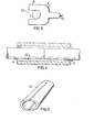
- Each flange 9, 10 is provided with an open recess 23, see Figure 3, which is slightly wider than the diameter of the sucker rod 4.
- the upper flange 9 contains a plurality of pressure chambers 12 in which plungers 11, lla are displaceable. By way of conduits, not shown, inside the assembly tool 8, and an external hose connection 13, the pressure chambers 12 can be connected to an external pressure source, not shown.
- the pressure chambers 12 can also be connected to an outlet pipe 14.
- the assembly tool 8 includes a handle 15 on which an operating lever 16 is provided. This actuates a valve (not shown) which places the pressure chambers in communication with the external pressure source when the lever 16 is pressed towards the handle 15.
- the assembly tool 8 When the coupling element 5 is to be clamped against the ends of the sucker rods the assembly tool 8 is placed so that the rods 4 fit into the recesses 23 in the flanges 9, 10.
- the lower flange 10, forming a support is in contact with the lower end of the inner sleeve 6 protruding from the outer sleeve 7.
- the lever 16 is then actuated, placing the pressure chambers 12 in communication with the external pressure source whereupon the plungers 11, lla, arranged radially outside the inner sleeve 6, are moved towards the outer sleeve 7, displacing this axially relative the inner sleeve 6.
- the pressure supply is discontinued when the sleeve has been displaced sufficiently far.
- a pressure-limiting valve for instance, being set to limit the pressure in the pressure supply circuit to a certain value corresponding to the desired clamping pressure between inner sleeve 6 and sucker rod 4.
- Position transducers sensing the position of the plungers 11, lla may be used instead of the pressure-limiting valve, in which case the transducer emits a signal when the plungers have travelled sufficiently far. The signal is utilized to discontinue the supply of pressure fluid to the pressure chambers 12.
- the outer sleeve 7 is provided with an oil channel 17 running axially through it and communicating via a branch channel 18 with the inner surface of the outer sleeve 7.
- pressurized oil is inserted between the outer surface of the inner sleeve 6 and the inner surface of the outer sleeve 7.
- the oil layer thus produced facilitates the relative movement of the two sleeves.
- the lower flange 10 is provided with a spring-loaded plug 19, the assembly tool 8 being placed so that the plug 19 closes the lower opening of the oil channel 17.
- One of the plungers lla is provided with an injection piston 20 located axially opposite the plug 19.
- the injection piston 20 closes the upper opening of the channel 17 and, via an insert 21 in the plunger lla, communicates with the relevant pressure chamber.
- this pressure chamber 12 When this pressure chamber 12 has been pressurized, oil will flow between the sleeves, after which the plungers 11, lla will displace the outer sleeve 7 along the inner sleeve 6 as described earlier.
- the coupling element is dismantled equally easily by inverting the tool 8 so that the flange 10 is against the upper end of the inner sleeve 6 and the plungers 11, lla exert pressure on the lower end of the outer sleeve 7.
- FIG. 4 An alternative to the coupling element described above is shown in Figures 4 and 5.
- This comprises an outer sleeve 7 and inner sleeve 22.
- the inner sleeve 22 is provided with axial slits in order to facilitate radial deformation.
- the outer surface of the inner sleeve 22 and the inner surface of the outer sleeve 7 are conical.
- the inner sleeve will therefore be pressed inwards against the sucker rods 4, thus locking them by means of friction, when the outer sleeve 7 is displaced along the inner sleeve 6.
- An assembly tool similar to that shown in Figure 2 is used. In this case the tool includes no oil injection piston nor sealing plug.
Landscapes
- Engineering & Computer Science (AREA)
- Mechanical Engineering (AREA)
- Life Sciences & Earth Sciences (AREA)
- Geology (AREA)
- Mining & Mineral Resources (AREA)
- Physics & Mathematics (AREA)
- Environmental & Geological Engineering (AREA)
- Fluid Mechanics (AREA)
- General Life Sciences & Earth Sciences (AREA)
- Geochemistry & Mineralogy (AREA)
- Shafts, Cranks, Connecting Bars, And Related Bearings (AREA)
- Mutual Connection Of Rods And Tubes (AREA)
Applications Claiming Priority (2)
| Application Number | Priority Date | Filing Date | Title |
|---|---|---|---|
| SE8504654A SE458944B (sv) | 1985-10-08 | 1985-10-08 | Saett att genom sammankoppling av pumpstaangselement, sucker rods, aastadkomma en pumpstaang foer oljeuppfordring samt foer saettets genomfoerande anvaenda sucker rods, kopplingselement och monteringsverktyg |
| SE8504654 | 1985-10-08 |
Publications (2)
| Publication Number | Publication Date |
|---|---|
| EP0221867A2 true EP0221867A2 (de) | 1987-05-13 |
| EP0221867A3 EP0221867A3 (de) | 1989-03-08 |
Family
ID=20361662
Family Applications (1)
| Application Number | Title | Priority Date | Filing Date |
|---|---|---|---|
| EP86850321A Withdrawn EP0221867A3 (de) | 1985-10-08 | 1986-09-22 | Verfahren zur Herstellung einer Pumpenstange durch Verbinden von Pumpgestänge für das Aufziehen von Öl und Pumpgestänge, Kupplungselemente und ein Werkzeug zum Verrichten dieses Verfahrens |
Country Status (3)
| Country | Link |
|---|---|
| EP (1) | EP0221867A3 (de) |
| SE (1) | SE458944B (de) |
| SU (1) | SU1593577A3 (de) |
Cited By (3)
| Publication number | Priority date | Publication date | Assignee | Title |
|---|---|---|---|---|
| CN106425988A (zh) * | 2016-08-25 | 2017-02-22 | 浙江亚太机电股份有限公司 | 柱塞泵缸体皮碗装配装置及装配方法 |
| US9982494B2 (en) | 2012-07-12 | 2018-05-29 | Ace Oil Tools As | Device arranged for attaching a pipe stem on a tubular body |
| CN110848130A (zh) * | 2019-11-14 | 2020-02-28 | 辽宁新华仪器有限公司 | 一种新型高强度大泵普通脱接器 |
Family Cites Families (4)
| Publication number | Priority date | Publication date | Assignee | Title |
|---|---|---|---|---|
| US3938853A (en) * | 1974-05-01 | 1976-02-17 | Christensen Diamond Products Company | Shrink-fit sleeve apparatus for drill strings |
| US4063412A (en) * | 1976-11-04 | 1977-12-20 | Owatonna Tool Company | Puller tool |
| GB2101708B (en) * | 1981-07-15 | 1985-05-09 | Skf Svenska Kullagerfab Ab | Shaft couplings |
| GB2114187A (en) * | 1982-01-23 | 1983-08-17 | Benteler Werke Ag | A pump rod for a pump string |
-
1985
- 1985-10-08 SE SE8504654A patent/SE458944B/sv not_active IP Right Cessation
-
1986
- 1986-09-22 EP EP86850321A patent/EP0221867A3/de not_active Withdrawn
- 1986-10-08 SU SU864028270A patent/SU1593577A3/ru active
Cited By (5)
| Publication number | Priority date | Publication date | Assignee | Title |
|---|---|---|---|---|
| US9982494B2 (en) | 2012-07-12 | 2018-05-29 | Ace Oil Tools As | Device arranged for attaching a pipe stem on a tubular body |
| US10767424B2 (en) | 2012-07-12 | 2020-09-08 | Ace Oil Tools As | Device arranged for attaching a pipe stem on a tubular body |
| CN106425988A (zh) * | 2016-08-25 | 2017-02-22 | 浙江亚太机电股份有限公司 | 柱塞泵缸体皮碗装配装置及装配方法 |
| CN106425988B (zh) * | 2016-08-25 | 2018-07-17 | 浙江亚太机电股份有限公司 | 柱塞泵缸体皮碗装配装置及装配方法 |
| CN110848130A (zh) * | 2019-11-14 | 2020-02-28 | 辽宁新华仪器有限公司 | 一种新型高强度大泵普通脱接器 |
Also Published As
| Publication number | Publication date |
|---|---|
| SE458944B (sv) | 1989-05-22 |
| SE8504654D0 (sv) | 1985-10-08 |
| EP0221867A3 (de) | 1989-03-08 |
| SU1593577A3 (ru) | 1990-09-15 |
| SE8504654L (sv) | 1987-04-09 |
Similar Documents
| Publication | Publication Date | Title |
|---|---|---|
| US4608739A (en) | Connector of and sealing of tubular members | |
| EP1322883B1 (de) | Fitting zum inneren verpressen | |
| EP0480478A1 (de) | Rohrkupplung | |
| KR100622360B1 (ko) | 마멸 손상을 감소시키기 위한 릴리프를 구비한 페룰 | |
| US4844516A (en) | Connector for coil tubing or the like | |
| EP2069646B1 (de) | Gewindeverschluss mit vorab festgelegtem drehmoment | |
| EP1141607B1 (de) | Rohrverbindung | |
| US6419278B1 (en) | Automotive hose coupling | |
| US4406561A (en) | Sucker rod assembly | |
| US4363505A (en) | Pipe coupling | |
| US4434811A (en) | Coupling seal and method of assembly | |
| CA2439133A1 (en) | Method of laying pipe-in-pipe structures and device for use therein | |
| US4769892A (en) | Pipe joining method | |
| US5261493A (en) | Method of testing snap type pipe connectors | |
| EP0221867A2 (de) | Verfahren zur Herstellung einer Pumpenstange durch Verbinden von Pumpgestänge für das Aufziehen von Öl und Pumpgestänge, Kupplungselemente und ein Werkzeug zum Verrichten dieses Verfahrens | |
| US20050248154A1 (en) | Threaded connection for oil field applications | |
| US4629220A (en) | Method and apparatus for quick-coupling connecting nipple for plastic pipe | |
| AU7663194A (en) | Pipe connector | |
| JPS61286683A (ja) | 弁組立体 | |
| FI79397B (fi) | Roerkoppling. | |
| US20070096461A1 (en) | Crimped hose fitting | |
| US5518275A (en) | Device for coupling and flaring a metal pipe | |
| WO1997035137A1 (en) | Pipeline coupling | |
| JPH02236087A (ja) | 管をアダプタに回収可能かつ半取外し可能に連結する方法 | |
| EP0793046B1 (de) | Verfahren zur Lehrung und zum Verbinden eines Metallrohres |
Legal Events
| Date | Code | Title | Description |
|---|---|---|---|
| PUAI | Public reference made under article 153(3) epc to a published international application that has entered the european phase |
Free format text: ORIGINAL CODE: 0009012 |
|
| AK | Designated contracting states |
Kind code of ref document: A2 Designated state(s): AT BE CH DE FR GB IT LI LU NL |
|
| PUAL | Search report despatched |
Free format text: ORIGINAL CODE: 0009013 |
|
| AK | Designated contracting states |
Kind code of ref document: A3 Designated state(s): AT BE CH DE FR GB IT LI LU NL |
|
| STAA | Information on the status of an ep patent application or granted ep patent |
Free format text: STATUS: THE APPLICATION IS DEEMED TO BE WITHDRAWN |
|
| 18D | Application deemed to be withdrawn |
Effective date: 19890909 |
|
| RIN1 | Information on inventor provided before grant (corrected) |
Inventor name: KULLMAN, RALF Inventor name: SUNDBERG, STAFFAN |