EP0221948B1 - Bohrstiftanpassungsgerät - Google Patents
Bohrstiftanpassungsgerät Download PDFInfo
- Publication number
- EP0221948B1 EP0221948B1 EP86902940A EP86902940A EP0221948B1 EP 0221948 B1 EP0221948 B1 EP 0221948B1 EP 86902940 A EP86902940 A EP 86902940A EP 86902940 A EP86902940 A EP 86902940A EP 0221948 B1 EP0221948 B1 EP 0221948B1
- Authority
- EP
- European Patent Office
- Prior art keywords
- drill
- adapter
- pivot
- drill rod
- parts
- Prior art date
- Legal status (The legal status is an assumption and is not a legal conclusion. Google has not performed a legal analysis and makes no representation as to the accuracy of the status listed.)
- Expired
Links
- 239000011435 rock Substances 0.000 claims abstract description 3
- 239000002689 soil Substances 0.000 claims abstract description 3
- 238000005553 drilling Methods 0.000 abstract description 17
- 230000008878 coupling Effects 0.000 abstract 1
- 238000010168 coupling process Methods 0.000 abstract 1
- 238000005859 coupling reaction Methods 0.000 abstract 1
- 238000009527 percussion Methods 0.000 abstract 1
Images


Classifications
-
- E—FIXED CONSTRUCTIONS
- E21—EARTH OR ROCK DRILLING; MINING
- E21B—EARTH OR ROCK DRILLING; OBTAINING OIL, GAS, WATER, SOLUBLE OR MELTABLE MATERIALS OR A SLURRY OF MINERALS FROM WELLS
- E21B10/00—Drill bits
- E21B10/26—Drill bits with leading portion, i.e. drill bits with a pilot cutter; Drill bits for enlarging the borehole, e.g. reamers
- E21B10/32—Drill bits with leading portion, i.e. drill bits with a pilot cutter; Drill bits for enlarging the borehole, e.g. reamers with expansible cutting tools
- E21B10/327—Drill bits with leading portion, i.e. drill bits with a pilot cutter; Drill bits for enlarging the borehole, e.g. reamers with expansible cutting tools the cutter being pivoted about a longitudinal axis
-
- E—FIXED CONSTRUCTIONS
- E21—EARTH OR ROCK DRILLING; MINING
- E21B—EARTH OR ROCK DRILLING; OBTAINING OIL, GAS, WATER, SOLUBLE OR MELTABLE MATERIALS OR A SLURRY OF MINERALS FROM WELLS
- E21B10/00—Drill bits
- E21B10/36—Percussion drill bits
- E21B10/38—Percussion drill bits characterised by conduits or nozzles for drilling fluids
-
- E—FIXED CONSTRUCTIONS
- E21—EARTH OR ROCK DRILLING; MINING
- E21B—EARTH OR ROCK DRILLING; OBTAINING OIL, GAS, WATER, SOLUBLE OR MELTABLE MATERIALS OR A SLURRY OF MINERALS FROM WELLS
- E21B10/00—Drill bits
- E21B10/36—Percussion drill bits
- E21B10/40—Percussion drill bits with leading portion
Definitions
- the present invention relates to a drill adapter intended for rock and soil drilling operations and being of the kind adapted for connection between a drill rod and a drill bit in a manner to allow the drill bit to be positioned eccentrically in relation to the geometric longitudinal axis of the drill rod (cf. US-A-3648 789).
- a drill adapter intended for rock and soil drilling operations and being of the kind adapted for connection between a drill rod and a drill bit in a manner to allow the drill bit to be positioned eccentrically in relation to the geometric longitudinal axis of the drill rod (cf. US-A-3648 789).
- the use of such an adapter enables holes of larger diameter than that of the drill bit to be drilled by causing the bit to rotate around the axis of the drill rod during a drilling operation.
- a known drill adapter of this kind includes a forward part, to which the drill bit is attached, and a rearward part, said parts being rotatably joined at an inclined abutment surface common to both parts, so that when the forward adapter part is rotated relative to the rearward part said part in swung outwardly and angled obliquely to the geometric longitudinal axis of the drilling rod.
- Another known device for eccentric compressed-air drilling purposes includes a so-called off-centre drill bit which comprises a guide, an especially designed pilot drill, and a reamer arranged therebetween.
- the eccentric function of this device is achieved through the reamer, which by rotating the same through 180° can be moved radially outwards and inwards relative to the pilot drill located in the drill hole and in front of the reamer.
- An object of the present invention is to provide an improved drill adapter of the kind described in the introduction to which there can be connected a conventional drilling bit which can be adjusted between a centric and eccentric position without being positioned obliquely in the drill hole.
- the drill adapter illustrated in Fig. 1 comprises mainly two parts, i.e. an upper part 10 and a lower part 30 which can be adjusted positionally in relation to the upper part 10, between a centric and an eccentric position.
- the upper adapter part 10 has a connecting end 11 provided with an internal screwthread 12 (for example an API-type screwthread) for connecting the adapter to one end of a drill rod (not shown), optionally via an intermediately connected down-the-hole drill or a hammer means, and presents a journal or bearing plate 21.
- the lower adapter part 30 has a journal or bearing plate 41 and a connecting end 31 on which there is provided an external screwthread 32 for connecting the adapter to a conventional drill bit not shown.
- a central channel 17 (Fig. 3) which provides a free axial passage between the two adapter parts, both in the centric and eccentric positions thereof.
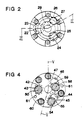
- the lower journal plate 41 presents a plurality of axial recesses or notches (Fig. 4) for pivotally journalling the lower adapter part 30 to the upper part 10 and for attaching the journal plate 41 to the lower connecting end 31.
- journalling of the two adapter parts for pivotal action between the aforesaid two positions is effected by providing the lower journal plate 41 with firstly an eccentrically located bore 42 which merges with a lower bore-enlargement 43 which accommodates from beneath a pivot peg 50 having an enlarged bottom-head 51, and secondly two slots which are spaced from the bore 42 and extend in circular-arcuate fashion thereto and which exhibit lower slot-enlargements 45, 47 each of which receives from beneath a pivot-restricting peg 54 and 58 having a respective enlarged lower head portion 55 and 59.
- firstly two guide pins 61, 61 each of which is accommodated in a respective bore 48 in the plate 41 (Fig. 3) and a respective bore 33 in the lower connecting end 31, and secondly four screw-joint means 60 let into the plate 41 and accommodated in bores 49 and screwthread holes 34 respectively (Fig. 5).
- the upper journal plate 21 has three throughpassing bores 22, 24, 26 which accommodate the pegs upstanding from the lower bearing plate 41, i.e. the pivot peg 50 and the pivot-restricting pegs 54 and 58 (Fig. 4).
- the upper journal plate 21 is secured to the pegs 50, 54 and 58 by means of similar screw- joints - of which only the joint comprising screw 53, enlarged bush 52 for the pivot peg 50 is shown in Fig. 3 - arranged in holes 23, 25 and 27 respectively.
- the upper connecting end 11 of the adapter is connected with the upper journal plate 21 by means of two guide pins accommodated in respective blind bores, of which guide pins one 18 is illustrated in Fig. 5 accommodated in blind bores 19 and 20, and by means of a plurality of circumferentially distributed and uniformly spaced screw connections which, as will be seen from Fig. 3, are let into the upper surface of the connecting end 11 as shown at 13 and extend through bores 14 in said connecting end 11 to engage screw-threaded bores 28 in the upper journal plate 21.
- the lower part of the central channel 17 is widened, at 29, in the upper journal plate 21, so as not to choke the air flow when the adapter is adjusted to its eccentric position and used for compressed-air drilling purposes.
- a drill adapter according to the present invention is intended to be used in the following manner.
- the upper connecting end 11 of the adapter Prior to drilling the upper connecting end 11 of the adapter is screwed, with the aid of screwthread 12, to one end of a drill rod (not shown) or, in the case of impact drilling, to an intermediate hammer assembly.
- the lower connecting end 31 is screwed directly to a drill bit, via the screwthread 32.
- the drill rod located centrally in the drill hole will rotate, and therewith also the adapter, in the direction of arrow 73 (Fig. 1).
- the lower part 30 of the adapter will be twisted in the opposite direction around the pivot peg 50 relative to the upper adapter part 10, to the eccentric position defined by the pegs 54, 58.
- the centre part of the drill bit will circle around the axis of the drill rod, so that the drill hole established by the drill bit will obtain a radius corresponding to the sum of the radius of the drill bit and the eccentricity of the adapter.
- the drill hole is sufficiently large to permit the casing tube to be driven down into the hole in a troublefree manner.
- the drill rod When drilling is completed the drill rod is rotated in a direction opposite to that indicated by arrow 73. so as to return the adapter to the centric position, as a result of frictional engagement of the drill bit with the bottom of the drill hole. The arrangement can then be withdrawn from the drill hole, without being hindered by the casing tube.
Landscapes
- Engineering & Computer Science (AREA)
- Geology (AREA)
- Mining & Mineral Resources (AREA)
- Life Sciences & Earth Sciences (AREA)
- General Life Sciences & Earth Sciences (AREA)
- Fluid Mechanics (AREA)
- Environmental & Geological Engineering (AREA)
- Physics & Mathematics (AREA)
- Mechanical Engineering (AREA)
- Geochemistry & Mineralogy (AREA)
- Earth Drilling (AREA)
- Drilling Tools (AREA)
- Perforating, Stamping-Out Or Severing By Means Other Than Cutting (AREA)
- Paper (AREA)
- Liquid Developers In Electrophotography (AREA)
- Surgical Instruments (AREA)
- Eye Examination Apparatus (AREA)
- Pharmaceuticals Containing Other Organic And Inorganic Compounds (AREA)
Claims (4)
Priority Applications (1)
| Application Number | Priority Date | Filing Date | Title |
|---|---|---|---|
| AT86902940T ATE41468T1 (de) | 1985-04-25 | 1986-04-24 | Bohrstiftanpassungsgeraet. |
Applications Claiming Priority (2)
| Application Number | Priority Date | Filing Date | Title |
|---|---|---|---|
| US06/727,224 US4682662A (en) | 1985-04-25 | 1985-04-25 | Drill adapter |
| US727224 | 2000-11-30 |
Publications (2)
| Publication Number | Publication Date |
|---|---|
| EP0221948A1 EP0221948A1 (de) | 1987-05-20 |
| EP0221948B1 true EP0221948B1 (de) | 1989-03-15 |
Family
ID=24921821
Family Applications (1)
| Application Number | Title | Priority Date | Filing Date |
|---|---|---|---|
| EP86902940A Expired EP0221948B1 (de) | 1985-04-25 | 1986-04-24 | Bohrstiftanpassungsgerät |
Country Status (11)
| Country | Link |
|---|---|
| US (1) | US4682662A (de) |
| EP (1) | EP0221948B1 (de) |
| JP (1) | JPS62502556A (de) |
| KR (1) | KR880700147A (de) |
| AT (1) | ATE41468T1 (de) |
| AU (1) | AU569658B2 (de) |
| DE (1) | DE3662416D1 (de) |
| DK (1) | DK626786D0 (de) |
| FI (1) | FI865308A7 (de) |
| NO (1) | NO865271L (de) |
| WO (1) | WO1986006435A1 (de) |
Families Citing this family (1)
| Publication number | Priority date | Publication date | Assignee | Title |
|---|---|---|---|---|
| SE460300B (sv) * | 1986-10-03 | 1989-09-25 | Loevab Loef Och Oestlund Ab | Roterbart borrverktyg med upprymningsdel till en saenkborrmaskin |
Citations (1)
| Publication number | Priority date | Publication date | Assignee | Title |
|---|---|---|---|---|
| US3848683A (en) * | 1972-02-10 | 1974-11-19 | Atlas Copco Ab | Method and means for drilling |
Family Cites Families (8)
| Publication number | Priority date | Publication date | Assignee | Title |
|---|---|---|---|---|
| US1754830A (en) * | 1926-11-20 | 1930-04-15 | John W Macclatchie | Underreamer |
| US1745650A (en) * | 1927-10-19 | 1930-02-04 | Grant John | Expanding roller underreamer |
| GB963670A (en) * | 1962-03-01 | 1964-07-15 | Skanska Cementgjuteriet Ab | Improvements in or relating to deep drills |
| FI40998B (de) * | 1962-07-09 | 1969-04-30 | Atlas Copco Ab | |
| US3416616A (en) * | 1967-03-01 | 1968-12-17 | Skanska Cementgjuteriet Ab | Deep drills with eccentric bits |
| SE325005B (de) * | 1968-10-16 | 1970-06-22 | Atlas Copco Ab | |
| SE367040B (de) * | 1972-05-03 | 1974-05-13 | Stabilator Ab | |
| SE421551B (sv) * | 1980-03-26 | 1982-01-04 | Sandvik Ab | Borrverktyg for rotations- och/eller slagborrning |
-
1985
- 1985-04-25 US US06/727,224 patent/US4682662A/en not_active Expired - Fee Related
-
1986
- 1986-04-24 EP EP86902940A patent/EP0221948B1/de not_active Expired
- 1986-04-24 FI FI865308A patent/FI865308A7/fi not_active IP Right Cessation
- 1986-04-24 WO PCT/SE1986/000189 patent/WO1986006435A1/en not_active Ceased
- 1986-04-24 JP JP61502521A patent/JPS62502556A/ja active Pending
- 1986-04-24 AU AU57794/86A patent/AU569658B2/en not_active Ceased
- 1986-04-24 AT AT86902940T patent/ATE41468T1/de not_active IP Right Cessation
- 1986-04-24 DE DE8686902940T patent/DE3662416D1/de not_active Expired
- 1986-12-23 NO NO865271A patent/NO865271L/no unknown
- 1986-12-23 DK DK626786A patent/DK626786D0/da not_active Application Discontinuation
- 1986-12-24 KR KR860700927A patent/KR880700147A/ko not_active Withdrawn
Patent Citations (1)
| Publication number | Priority date | Publication date | Assignee | Title |
|---|---|---|---|---|
| US3848683A (en) * | 1972-02-10 | 1974-11-19 | Atlas Copco Ab | Method and means for drilling |
Also Published As
| Publication number | Publication date |
|---|---|
| FI865308L (fi) | 1986-12-23 |
| KR880700147A (ko) | 1988-02-20 |
| FI865308A0 (fi) | 1986-12-23 |
| DK626786A (da) | 1986-12-23 |
| US4682662A (en) | 1987-07-28 |
| AU569658B2 (en) | 1988-02-11 |
| NO865271D0 (no) | 1986-12-23 |
| EP0221948A1 (de) | 1987-05-20 |
| JPS62502556A (ja) | 1987-10-01 |
| ATE41468T1 (de) | 1989-04-15 |
| AU5779486A (en) | 1986-11-18 |
| WO1986006435A1 (en) | 1986-11-06 |
| DE3662416D1 (en) | 1989-04-20 |
| NO865271L (no) | 1987-02-19 |
| FI865308A7 (fi) | 1986-12-23 |
| DK626786D0 (da) | 1986-12-23 |
Similar Documents
| Publication | Publication Date | Title |
|---|---|---|
| US3387673A (en) | Rotary percussion gang drill | |
| US6450269B1 (en) | Method and bit for directional horizontal boring | |
| US5052503A (en) | Eccentric drilling tool | |
| US7152702B1 (en) | Modular system for a back reamer and method | |
| US3765493A (en) | Dual bit drilling tool | |
| CA2585564C (en) | Rock drill bit | |
| US6311793B1 (en) | Rock bit nozzle and retainer assembly | |
| EP1402146B1 (de) | Erdbohrvorrichtung | |
| WO1996039568A1 (en) | Rotary cone drill bit modular arm | |
| CN100342113C (zh) | 钻头组件 | |
| US6311790B1 (en) | Removable boring head with tapered shank connector | |
| US5934394A (en) | Drill means | |
| EP0851090A1 (de) | Im-loch bohrhammer | |
| US4729439A (en) | Gang drill construction | |
| AU655581B2 (en) | A down-the-hole drill tool for drilling in advance of a casing tube | |
| JPH0610582A (ja) | ドリルビット | |
| JP4091249B2 (ja) | ダウンホール掘削用の掘削工具、リーマー手段、及びその工具に使用するボデー要素 | |
| US6021856A (en) | Bit retention system | |
| EP0221948B1 (de) | Bohrstiftanpassungsgerät | |
| US3469641A (en) | Reaming bit assembly | |
| US6533052B2 (en) | Drill bit for impact-assisted directional boring | |
| US20030010539A1 (en) | Drill steel for drilling mine roofs | |
| US5366032A (en) | Rock bit | |
| US6112835A (en) | Drilling apparatus having a radially displaceable reamer | |
| AU719474B2 (en) | Stabiliser for borehole drilling apparatus |
Legal Events
| Date | Code | Title | Description |
|---|---|---|---|
| PUAI | Public reference made under article 153(3) epc to a published international application that has entered the european phase |
Free format text: ORIGINAL CODE: 0009012 |
|
| 17P | Request for examination filed |
Effective date: 19870105 |
|
| AK | Designated contracting states |
Kind code of ref document: A1 Designated state(s): AT BE CH DE FR GB IT LI LU NL SE |
|
| 17Q | First examination report despatched |
Effective date: 19880201 |
|
| GRAA | (expected) grant |
Free format text: ORIGINAL CODE: 0009210 |
|
| AK | Designated contracting states |
Kind code of ref document: B1 Designated state(s): AT BE CH DE FR GB IT LI LU NL SE |
|
| PG25 | Lapsed in a contracting state [announced via postgrant information from national office to epo] |
Ref country code: IT Free format text: LAPSE BECAUSE OF FAILURE TO SUBMIT A TRANSLATION OF THE DESCRIPTION OR TO PAY THE FEE WITHIN THE PRE;WARNING: LAPSES OF ITALIAN PATENTS WITH EFFECTIVE DATE BEFORE 2007 MAY HAVE OCCURRED AT ANY TIME BEFORE 2007. THE CORRECT EFFECTIVE DATE MAY BE DIFFERENT FROM THE ONE RECORDED.SCRIBED TIME-LIMIT Effective date: 19890315 Ref country code: SE Effective date: 19890315 Ref country code: CH Effective date: 19890315 Ref country code: LI Effective date: 19890315 Ref country code: NL Effective date: 19890315 Ref country code: FR Free format text: THE PATENT HAS BEEN ANNULLED BY A DECISION OF A NATIONAL AUTHORITY Effective date: 19890315 Ref country code: AT Effective date: 19890315 |
|
| REF | Corresponds to: |
Ref document number: 41468 Country of ref document: AT Date of ref document: 19890415 Kind code of ref document: T |
|
| REF | Corresponds to: |
Ref document number: 3662416 Country of ref document: DE Date of ref document: 19890420 |
|
| PG25 | Lapsed in a contracting state [announced via postgrant information from national office to epo] |
Ref country code: BE Effective date: 19890430 Ref country code: LU Free format text: LAPSE BECAUSE OF NON-PAYMENT OF DUE FEES Effective date: 19890430 |
|
| REG | Reference to a national code |
Ref country code: CH Ref legal event code: PL |
|
| EN | Fr: translation not filed | ||
| NLV1 | Nl: lapsed or annulled due to failure to fulfill the requirements of art. 29p and 29m of the patents act | ||
| BERE | Be: lapsed |
Owner name: VANCURA VLADIMIR Effective date: 19890430 |
|
| PLBE | No opposition filed within time limit |
Free format text: ORIGINAL CODE: 0009261 |
|
| STAA | Information on the status of an ep patent application or granted ep patent |
Free format text: STATUS: NO OPPOSITION FILED WITHIN TIME LIMIT |
|
| PG25 | Lapsed in a contracting state [announced via postgrant information from national office to epo] |
Ref country code: DE Effective date: 19900201 |
|
| 26N | No opposition filed | ||
| PG25 | Lapsed in a contracting state [announced via postgrant information from national office to epo] |
Ref country code: GB Effective date: 19900424 |
|
| GBPC | Gb: european patent ceased through non-payment of renewal fee |