EP0221987B1 - Perfectionnements aux cyclotrons - Google Patents
Perfectionnements aux cyclotrons Download PDFInfo
- Publication number
- EP0221987B1 EP0221987B1 EP86903472A EP86903472A EP0221987B1 EP 0221987 B1 EP0221987 B1 EP 0221987B1 EP 86903472 A EP86903472 A EP 86903472A EP 86903472 A EP86903472 A EP 86903472A EP 0221987 B1 EP0221987 B1 EP 0221987B1
- Authority
- EP
- European Patent Office
- Prior art keywords
- magnetic field
- cyclotron
- beam space
- pole pieces
- chamber
- Prior art date
- Legal status (The legal status is an assumption and is not a legal conclusion. Google has not performed a legal analysis and makes no representation as to the accuracy of the status listed.)
- Expired
Links
- 230000005291 magnetic effect Effects 0.000 claims abstract description 36
- 230000005294 ferromagnetic effect Effects 0.000 claims abstract description 6
- 238000005086 pumping Methods 0.000 claims abstract description 5
- 150000002500 ions Chemical class 0.000 claims description 29
- 239000002245 particle Substances 0.000 claims description 29
- 239000011888 foil Substances 0.000 claims description 6
- XEEYBQQBJWHFJM-UHFFFAOYSA-N Iron Chemical compound [Fe] XEEYBQQBJWHFJM-UHFFFAOYSA-N 0.000 abstract description 16
- 229910052742 iron Inorganic materials 0.000 abstract description 8
- 238000010884 ion-beam technique Methods 0.000 abstract 2
- 230000004323 axial length Effects 0.000 abstract 1
- 239000001307 helium Substances 0.000 description 7
- 229910052734 helium Inorganic materials 0.000 description 7
- SWQJXJOGLNCZEY-UHFFFAOYSA-N helium atom Chemical compound [He] SWQJXJOGLNCZEY-UHFFFAOYSA-N 0.000 description 7
- 239000007788 liquid Substances 0.000 description 6
- IJGRMHOSHXDMSA-UHFFFAOYSA-N Atomic nitrogen Chemical compound N#N IJGRMHOSHXDMSA-UHFFFAOYSA-N 0.000 description 4
- 230000007704 transition Effects 0.000 description 4
- RYGMFSIKBFXOCR-UHFFFAOYSA-N Copper Chemical compound [Cu] RYGMFSIKBFXOCR-UHFFFAOYSA-N 0.000 description 2
- 230000001133 acceleration Effects 0.000 description 2
- 229910052802 copper Inorganic materials 0.000 description 2
- 239000010949 copper Substances 0.000 description 2
- 230000003993 interaction Effects 0.000 description 2
- 229910052757 nitrogen Inorganic materials 0.000 description 2
- 230000001360 synchronised effect Effects 0.000 description 2
- OKTJSMMVPCPJKN-UHFFFAOYSA-N Carbon Chemical compound [C] OKTJSMMVPCPJKN-UHFFFAOYSA-N 0.000 description 1
- UFHFLCQGNIYNRP-UHFFFAOYSA-N Hydrogen Chemical compound [H][H] UFHFLCQGNIYNRP-UHFFFAOYSA-N 0.000 description 1
- 230000005540 biological transmission Effects 0.000 description 1
- UQMRAFJOBWOFNS-UHFFFAOYSA-N butyl 2-(2,4-dichlorophenoxy)acetate Chemical compound CCCCOC(=O)COC1=CC=C(Cl)C=C1Cl UQMRAFJOBWOFNS-UHFFFAOYSA-N 0.000 description 1
- 229910052799 carbon Inorganic materials 0.000 description 1
- 238000010276 construction Methods 0.000 description 1
- 239000002826 coolant Substances 0.000 description 1
- 230000000694 effects Effects 0.000 description 1
- 238000000605 extraction Methods 0.000 description 1
- 239000003302 ferromagnetic material Substances 0.000 description 1
- 239000007789 gas Substances 0.000 description 1
- 230000002452 interceptive effect Effects 0.000 description 1
- 238000010849 ion bombardment Methods 0.000 description 1
- 239000000463 material Substances 0.000 description 1
- 238000009203 neutron therapy Methods 0.000 description 1
- 230000005855 radiation Effects 0.000 description 1
- 238000002601 radiography Methods 0.000 description 1
- 239000000725 suspension Substances 0.000 description 1
Images



Classifications
-
- H—ELECTRICITY
- H05—ELECTRIC TECHNIQUES NOT OTHERWISE PROVIDED FOR
- H05H—PLASMA TECHNIQUE; PRODUCTION OF ACCELERATED ELECTRICALLY-CHARGED PARTICLES OR OF NEUTRONS; PRODUCTION OR ACCELERATION OF NEUTRAL MOLECULAR OR ATOMIC BEAMS
- H05H13/00—Magnetic resonance accelerators; Cyclotrons
Definitions
- the present invention relates to cyclotrons which are devices for accelerating a beam of ionized particles around a substantially spiral path lying normal to an axial magnetic field, so as to produce a continuous output beam of particles at the high energy levels required for research and other purposes involving ion bombardment.
- a beam of ionized particles travels past electrodes which are paired to have opposing electrical voltages applied to them. With each transition of the ionized particles past the differential voltage of a pair of electrodes, the particles gain energy.
- the voltages applied to the electrodes are alternating voltages of radio frequency and are applied at a frequency to synchronise with the transitions of the ionized particles.
- the particles can be brought back up to the required speed and thus kept in synchronism with the radio frequency energisation by increasing the strength of the magnetic field with radius.
- the magnetic field is then said to have an isochronous field shape. This field shape does, however, cause a loss of focussing of the beam of ionized particles and to re-focus the particles an azimuthal variation or'flutter' is incorporated into the magnetic field.
- Cyclotrons are usually constructed using resistive magnet coils enclosed within ferro-magnetic yokes, but the bulk and weight of these magnets has limited their use to establishments with large premises to house them. In addition, the amount of energy required to power the resistive coils puts a substantial demand on the electrical supply.
- US-A-3868522 describes a cyclotron which has no iron yoke but which suffers from a number of problems.
- our separate liquid helium environments are required to cool the four superconducting coils to their operating temperatures.
- the construction of this prior art is limited in that it is essential to provide an even number of pairs, at least four in number, of generally flat conducting plates to define the RF cavity.
- a cyclotron comprises a superconducting magnet having at least one cylindrical magnet coil arranged in a cryostat to provide a magnetic field extending axially of the coil, the cryostat defining an axial chamber having a substantially circular cross-section and containing the magnetic field, wherein the superconducting magnet provides yokeless means for generating the magnetic field, wherein interacting means are disposed in the chamber and arranged to interact with the magnetic field to provide a 'flutter' or variation of the axial magnetic field in the azimuthal direction in relation to the axis of the axial chamber and to provide an isochronous variation of the axial magnetic field in the radial direction from the axis, and wherein resonant cavity means are disposed in the chamber and arranged to provide an accelerating field for a beam of ionised particles, the interacting means and the resonant cavity means together defining a beam space disposed in the radial direction from the axis in which the beam of ion
- the present invention provides a design of cyclotron using a superconducting magnet which has no iron yoke.
- the desired isochronous field variation in the radial direction and the desired variation of magnetic field in the azimuth direction are both achieved.
- the invention provides an improved cyclotron over that described in US-A-3868522 since the or each cylindrical magnet coil has an internal radius greater than the outer radius of the beam space. This allows a single coolant vessel to be used and also allows the cyclotron accelerating components to be inserted without interfering with the cryostat containing the superconducting coils. Furthermore, this arrangment allows the use of RF cavity resonators instead of plates and the possibility of threefold symmetry.
- said interacting means comprise sector-shaped ferro-magnetic pole pieces and said resonant cavity means comprise sector-shaped members interposed between said pole pieces.
- the accelerating action of the cyclotron is provided to a stream or beam of ionized particles which is continuously injected into the centre of a disc-shaped beam space 10.
- An axial magnetic field extends parallel to a central axis 11 of the cyclotron (beam space 10 extending radially outwards from this axis 11) and receives azimuthal and radial variations in the region of beam space 10 by interaction with interacting means in the form of soft iron pole pieces 12 through to 17.
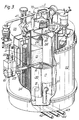
- the axial magnetic field is provided by yokeless means in the form of a superconducting magnet 29 having a set of superconducting magnet coils 21 through to 24 which are housed in a cryostat 25, so that the coils are kept close to absolute zero for superconducting operation.
- the cryostat 25 is of cylindrical shape and defines a central cylindrical axially extending opening or chamber 26. Constructional details of the cryostat 25 will be described later.
- the soft iron pole pieces are provided as three upper pole pieces 12, 13, 14 disposed at 120° intervals around the axis 11 within chamber 26.
- a lower set of soft iron pole pieces 15, 16, 17 is also disposed at 120° intervals around the axis 11 within the chamber 26, with lower pole piece 15 aligned axially with upper pole piece 12 and the other pole pieces similarly aligned.
- the shape, disposition and magnetic properties of the pole pieces are designed and selected so as to provide the desired variations in field strength to the axial field.
- Figures 6 and 7 show respectively the azimuthal variations and the isochronous radial shape of the magnetic field.
- Figure 6 shows the field strength varies around the circumference of the cyclotron, wihy the position of two of the pole pieces 12-17 shown at 60° and 180°.
- Figure 7 shows the radial variation of the magnetic field from 3.5 T at the axis 11 of the cyclotron, to 3.6 T at the circumference E, these figures for field strength being merely typical.
- radio frequency energisation is supplied to the beam of particles orbiting in the beam space 10 through radio frequency cavity means in the form of members 30, 31 also disposed in chamber 26.
- These members comprise an upper set of sector-shaped extensions 32, 33, 34 spaced at 120° intervals around the axis 11 of the cyclotron and extending axially upwards from the beam space 10 and radially outwards from the axis 11 and interposed between the pole pieces 12 to 14.
- the extensions 32 through to 34 each comprise a prism-shaped copper shell 39 nested inside another larger prism-shaped copper shell 40, the shells 39, 40 being spaced apart to form a narrow cavity 41.
- the outer shells 40 are joined axially to adjacent shells at the centre of the cyclotron, as at 42, and the cavities 41 of all three extensions 32 through to 34, thus communicate at the centre.
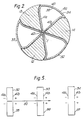
- Each extension appears, in a cross-section normal to axis 11, as in Figure 2, as a sector-shaped cavity strip having two arms 41a and 41b extending substantially radially outwards from axis 11 and with a circumferential arm 41c.
- a lower set of extensions 35, 36, 37 is similarly spaced around axis 11, similarly joined one to the other at the centre, similarly disposed in chamber 26 and similarly interposed between the lower pole pieces.
- Each extension 35-37 aligns axially with one of the extensions of the upper set.
- each of extensions 32 through to 34 lies axially opposite an extension of the lower set 35 through to 37 and opposing extensions are spaced apart axially to define, in part, the beam space 10.
- the pole pieces 12 through to 14 lie axially opposite the pole pieces 15 through to 17 of the lower set and are also spaced apart axially to define, in part, the beam space 10.
- resonant cavity members 32 through to 37 circumferentially between the pole pieces 12 through to 17, allows the resonant cavities to be extended axially for as far as is necessary for them to provide efficient delivery of the radio frequency energisation. In the example, they are made to be one quarter of the wavelength of the required radio frequency energisation.
- the cavities 41 are closed at their ends remote from the beam space 10 to form quarter wave resonators.
- Radio frequency energisation is fed from respective co-axial cables 42 through to 44 into the cavities 41 between the inner and outer shells 39, 40, so as to produce a large sinusoidally oscillating voltage between the ends of the cavities adjacent the beam space 10.
- the cavities of all three extensions in the upper set along with all three cavities of the extensions in the lower set are energised in phase and, in the example, they are supplied with radio frequency waves at a frequency three times the revolution frequency of the ionized particles.
- FIG. 5 there is shown a developed axial section through the three radio cavity extensions of both upper and lower sets.
- the beam 50 travels from left to right, as shown, and the radio frequency energisation is synchronised to provide the required polarity to accelerate the particles as they pass each of the cavities.
- each of the ionized particles passes the two sides or shells making up each cavity and because the phase of the voltages applied to these sides is synchronised to provide accelerating voltages as the particles pass, the particles are given six accelerating voltage 'kicks' per revolution.
- Each voltage kick is typically 30 kV and the ion revolution frequency is 50 MHz, i.e. each orbit increases the energy by 180 kV and the cavity frequency is 150 MHz.
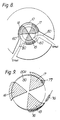
- the particles When the particles reach the required energisation they are removed from the cyclotron. As shown in Figure 8 using negative ions, at the appropriate point in the spiral path of the beam 80, the particles are caused to strike a thin carbon foil 60.
- This foil 60 strips negative charge from the ions, thereby converting them to positive ions. As such they are deflected by the axial magnetic field in a direction radially outwards and thus pass out of a delivery pipe 61.
- the foil can have any number of alternative positions depending on the energy required in the output particles: thus, by changing the position of the foil, alternative outputs of 10 MeV and 17 MeV can be obtained.
- the stream of ions is provided by an ion source 70 which is situated on top of the cyclotron.
- the ion source 70 emits a stream of negative ions radially outwards: the stream is turned immediately through 90° by the magnetic field and the majority of the concomitant hydrogen gas is removed at this point by differential vacuum pumping.
- the facility easily to remove gas from the ion stream, along with the facility for extremely efficient pumping of the beam space, contributes to the excellent overall efficiency of the cyclotron.
- the stream of negative ions from source 70 is shown at 71. It is turned immediately through 90° so as to be directed along the central axis 11 and passes through a hole 72 provided in the top of the resonant cavity members 32 to 34, on its passage to the beam space 10.
- the ion stream is again turned through 90°, as shown at 79, and then starts its orbits in the beam space 10.
- Figure 4 shows a cyclotron which is very similar to that shown in Figure 3.
- the ion generator is in the beam space 10 at 74, and is supplied from a services unit 75 along a tube 73, the ion stream issuing from a hole in tube 73 at 74.
- the ion stream is delivered to the centre of the beam space 10. At the centre of the beam space, this stream begins its spiral path into the flat disc-shaped beam space 10.
- a target which is the actual workpiece, is positioned within the beam space 10 in the path of the ion stream so that the ions impinge directly on it.
- the cavities can be made in a more efficient shape and can be provided in greater number than in conventional designs, thus providing greater acceleration per turn of the helical path of the ionised particles.
- each cavity extension is hollow and open at top and bottom thereby providing a clear, low impedance, axially extending path between the beam space 10 and a vacuum pump 55.
- Pump 55 is mounted on a plate 56 which closes the upper end of chamber 26, whilst a plate 57 closes the lower end.
- the cyclotron is thus constructed without an iron yoke making it very lightweight and portable. Such a cyclotron is very suitable for neutron radiography and neutron therapy.
- cryostat 25 the four cylindrical magnet coils 21, 22, 23, 24 in the cryostat 25 are mounted on a cylindrical former 85.
- the former 85 along with a cylindrical shell 86 and end plates 87, 38, defines a liquid helium bath having an entry 39 for passage of leads and for pouring in liquid helium so that the coils 21 through to 24 operate immersed in liquid helium as superconducting coils.
- a radiation shield 43 housed within the cryostat is a radiation shield 43 and a double walled cylindrical container 44 which includes a liquid nitrogen bath 44a.
- the container 44 is suspended from top and bottom plates 45, 46 of the cryostat by arms 48 and the helium bath is suspended from arms 47, all these suspension arms being made of material which resists the transmission of heat.
- the inner and outer cylindrical walls 51, 52 of the cryostat, together with top and bottom plates 54, 55 define a vacuum chamber which is evacuated to resist the ingress of heat.
- cryostat follows standard modern practice for superconducting magnets of high performance with the coils kept close to absolute zero in the bath of liquid helium and the rest of the structure designed to resist the ingress of heat and to minimise the boil-off of helium and nitrogen.
Landscapes
- Physics & Mathematics (AREA)
- Engineering & Computer Science (AREA)
- Plasma & Fusion (AREA)
- Spectroscopy & Molecular Physics (AREA)
- Particle Accelerators (AREA)
Abstract
Claims (10)
Applications Claiming Priority (2)
| Application Number | Priority Date | Filing Date | Title |
|---|---|---|---|
| GB858512804A GB8512804D0 (en) | 1985-05-21 | 1985-05-21 | Cyclotrons |
| GB8512804 | 1985-05-21 |
Publications (2)
| Publication Number | Publication Date |
|---|---|
| EP0221987A1 EP0221987A1 (fr) | 1987-05-20 |
| EP0221987B1 true EP0221987B1 (fr) | 1991-01-16 |
Family
ID=10579443
Family Applications (1)
| Application Number | Title | Priority Date | Filing Date |
|---|---|---|---|
| EP86903472A Expired EP0221987B1 (fr) | 1985-05-21 | 1986-05-21 | Perfectionnements aux cyclotrons |
Country Status (5)
| Country | Link |
|---|---|
| US (1) | US4943781A (fr) |
| EP (1) | EP0221987B1 (fr) |
| DE (1) | DE3676949D1 (fr) |
| GB (1) | GB8512804D0 (fr) |
| WO (1) | WO1986007229A1 (fr) |
Cited By (13)
| Publication number | Priority date | Publication date | Assignee | Title |
|---|---|---|---|---|
| US7728311B2 (en) | 2005-11-18 | 2010-06-01 | Still River Systems Incorporated | Charged particle radiation therapy |
| US8003964B2 (en) | 2007-10-11 | 2011-08-23 | Still River Systems Incorporated | Applying a particle beam to a patient |
| US8581523B2 (en) | 2007-11-30 | 2013-11-12 | Mevion Medical Systems, Inc. | Interrupted particle source |
| US8791656B1 (en) | 2013-05-31 | 2014-07-29 | Mevion Medical Systems, Inc. | Active return system |
| US8927950B2 (en) | 2012-09-28 | 2015-01-06 | Mevion Medical Systems, Inc. | Focusing a particle beam |
| US8933650B2 (en) | 2007-11-30 | 2015-01-13 | Mevion Medical Systems, Inc. | Matching a resonant frequency of a resonant cavity to a frequency of an input voltage |
| US8952634B2 (en) | 2004-07-21 | 2015-02-10 | Mevion Medical Systems, Inc. | Programmable radio frequency waveform generator for a synchrocyclotron |
| US9155186B2 (en) | 2012-09-28 | 2015-10-06 | Mevion Medical Systems, Inc. | Focusing a particle beam using magnetic field flutter |
| US9185789B2 (en) | 2012-09-28 | 2015-11-10 | Mevion Medical Systems, Inc. | Magnetic shims to alter magnetic fields |
| US9301384B2 (en) | 2012-09-28 | 2016-03-29 | Mevion Medical Systems, Inc. | Adjusting energy of a particle beam |
| US9545528B2 (en) | 2012-09-28 | 2017-01-17 | Mevion Medical Systems, Inc. | Controlling particle therapy |
| US9962560B2 (en) | 2013-12-20 | 2018-05-08 | Mevion Medical Systems, Inc. | Collimator and energy degrader |
| US10258810B2 (en) | 2013-09-27 | 2019-04-16 | Mevion Medical Systems, Inc. | Particle beam scanning |
Families Citing this family (41)
| Publication number | Priority date | Publication date | Assignee | Title |
|---|---|---|---|---|
| GB8701363D0 (en) * | 1987-01-22 | 1987-02-25 | Oxford Instr Ltd | Magnetic field generating assembly |
| US5015893A (en) * | 1988-07-16 | 1991-05-14 | Yugen Kaisha Chubuseimitsu | Motor structure with magnetic interference shield |
| GB8820628D0 (en) * | 1988-09-01 | 1988-10-26 | Amersham Int Plc | Proton source |
| US5032869A (en) * | 1990-04-06 | 1991-07-16 | General Electric Company | Axial thermal shield support for a MR magnet |
| US5083105A (en) * | 1990-04-06 | 1992-01-21 | General Electric Company | Axial support system for a mr magnet |
| US5034713A (en) * | 1990-04-06 | 1991-07-23 | General Electric Company | Radial support system for a MR magnet |
| BE1005530A4 (fr) * | 1991-11-22 | 1993-09-28 | Ion Beam Applic Sa | Cyclotron isochrone |
| US5290638A (en) * | 1992-07-24 | 1994-03-01 | Massachusetts Institute Of Technology | Superconducting joint with niobium-tin |
| US5463291A (en) * | 1993-12-23 | 1995-10-31 | Carroll; Lewis | Cyclotron and associated magnet coil and coil fabricating process |
| AU691028B2 (en) * | 1994-08-19 | 1998-05-07 | Amersham International Plc | Superconducting cyclotron and target for use in the production of heavy isotopes |
| AU706791B2 (en) * | 1994-08-19 | 1999-06-24 | Amersham International Plc | Target for use in the production of heavy isotopes |
| US5977554A (en) * | 1998-03-23 | 1999-11-02 | The Penn State Research Foundation | Container for transporting antiprotons |
| US6576916B2 (en) * | 1998-03-23 | 2003-06-10 | Penn State Research Foundation | Container for transporting antiprotons and reaction trap |
| US6414331B1 (en) | 1998-03-23 | 2002-07-02 | Gerald A. Smith | Container for transporting antiprotons and reaction trap |
| SE513191C2 (sv) * | 1998-09-29 | 2000-07-24 | Gems Pet Systems Ab | Snabbkoppling |
| EP1069809A1 (fr) * | 1999-07-13 | 2001-01-17 | Ion Beam Applications S.A. | Cyclotron isochrone et procédé d'extraction de particules chargées hors de ce cyclotron |
| US6130926A (en) * | 1999-07-27 | 2000-10-10 | Amini; Behrouz | Method and machine for enhancing generation of nuclear particles and radionuclides |
| US7577228B2 (en) * | 2002-10-28 | 2009-08-18 | General Electric Company | Transportable manufacturing facility for radioactive materials |
| US7656258B1 (en) | 2006-01-19 | 2010-02-02 | Massachusetts Institute Of Technology | Magnet structure for particle acceleration |
| JP5481070B2 (ja) * | 2006-01-19 | 2014-04-23 | マサチューセッツ インスティテュート オブ テクノロジー | 粒子加速のための磁場生成方法、磁石構造体及びその製造方法 |
| US8975836B2 (en) | 2012-07-27 | 2015-03-10 | Massachusetts Institute Of Technology | Ultra-light, magnetically shielded, high-current, compact cyclotron |
| TW201422278A (zh) | 2012-09-28 | 2014-06-16 | Mevion Medical Systems Inc | 粒子加速器之控制系統 |
| US10254739B2 (en) | 2012-09-28 | 2019-04-09 | Mevion Medical Systems, Inc. | Coil positioning system |
| EP2901823B1 (fr) | 2012-09-28 | 2021-12-08 | Mevion Medical Systems, Inc. | Contrôle de l'intensité d'un faisceau de particules |
| EP2901821B1 (fr) | 2012-09-28 | 2020-07-08 | Mevion Medical Systems, Inc. | Régénérateur de champ magnétique |
| US9730308B2 (en) | 2013-06-12 | 2017-08-08 | Mevion Medical Systems, Inc. | Particle accelerator that produces charged particles having variable energies |
| US10675487B2 (en) | 2013-12-20 | 2020-06-09 | Mevion Medical Systems, Inc. | Energy degrader enabling high-speed energy switching |
| US9661736B2 (en) | 2014-02-20 | 2017-05-23 | Mevion Medical Systems, Inc. | Scanning system for a particle therapy system |
| US9950194B2 (en) | 2014-09-09 | 2018-04-24 | Mevion Medical Systems, Inc. | Patient positioning system |
| JP6441508B2 (ja) * | 2015-05-26 | 2018-12-19 | アンタヤ サイエンス アンド テクノロジーAntaya Science & Technology | 超伝導フラッタコイル及び非磁性補強を有する等時性サイクロトロン |
| US10786689B2 (en) | 2015-11-10 | 2020-09-29 | Mevion Medical Systems, Inc. | Adaptive aperture |
| US10028369B2 (en) | 2016-03-17 | 2018-07-17 | Massachusetts Institute Of Technology | Particle acceleration in a variable-energy synchrocyclotron by a single-tuned variable-frequency drive |
| JP6602716B2 (ja) * | 2016-03-30 | 2019-11-06 | ジャパンスーパーコンダクタテクノロジー株式会社 | 超電導マグネット装置 |
| JP6546115B2 (ja) * | 2016-03-30 | 2019-07-17 | ジャパンスーパーコンダクタテクノロジー株式会社 | 超電導マグネット装置 |
| US10925147B2 (en) | 2016-07-08 | 2021-02-16 | Mevion Medical Systems, Inc. | Treatment planning |
| US11103730B2 (en) | 2017-02-23 | 2021-08-31 | Mevion Medical Systems, Inc. | Automated treatment in particle therapy |
| JP6940676B2 (ja) | 2017-06-30 | 2021-09-29 | メビオン・メディカル・システムズ・インコーポレーテッド | リニアモーターを使用して制御される構成可能コリメータ |
| DE102017217930A1 (de) * | 2017-10-09 | 2019-04-11 | Bruker Biospin Ag | Magnetanordnung mit Kryostat und Magnetspulensystem, mit Kältespeichern an den Stromzuführungen |
| EP3934751B1 (fr) | 2019-03-08 | 2024-07-17 | Mevion Medical Systems, Inc. | Collimateur et dégradeur d'énergie pour système de thérapie par particules |
| GB2640666A (en) | 2024-04-30 | 2025-11-05 | Univ Manchester | Cyclotron |
| CN119233513B (zh) * | 2024-08-19 | 2025-04-15 | 国电投核力同创(北京)科技有限公司 | 用于消色散偏转磁铁的调节块和消色散偏转磁铁调节方法 |
Family Cites Families (5)
| Publication number | Priority date | Publication date | Assignee | Title |
|---|---|---|---|---|
| US3794927A (en) * | 1970-01-20 | 1974-02-26 | Atomic Energy Commission | System for producing high energy positively charged particles |
| US3624527A (en) * | 1970-09-15 | 1971-11-30 | Atomic Energy Commission | Magnetically self-shaping septum for beam deflection |
| CA966893A (en) * | 1973-06-19 | 1975-04-29 | Her Majesty In Right Of Canada As Represented By Atomic Energy Of Canada Limited | Superconducting cyclotron |
| US3925676A (en) * | 1974-07-31 | 1975-12-09 | Ca Atomic Energy Ltd | Superconducting cyclotron neutron source for therapy |
| US4641104A (en) * | 1984-04-26 | 1987-02-03 | Board Of Trustees Operating Michigan State University | Superconducting medical cyclotron |
-
1985
- 1985-05-21 GB GB858512804A patent/GB8512804D0/en active Pending
-
1986
- 1986-05-21 EP EP86903472A patent/EP0221987B1/fr not_active Expired
- 1986-05-21 WO PCT/GB1986/000284 patent/WO1986007229A1/fr not_active Ceased
- 1986-05-21 DE DE8686903472T patent/DE3676949D1/de not_active Expired - Lifetime
-
1989
- 1989-07-18 US US07/382,035 patent/US4943781A/en not_active Expired - Fee Related
Cited By (19)
| Publication number | Priority date | Publication date | Assignee | Title |
|---|---|---|---|---|
| US8952634B2 (en) | 2004-07-21 | 2015-02-10 | Mevion Medical Systems, Inc. | Programmable radio frequency waveform generator for a synchrocyclotron |
| US8344340B2 (en) | 2005-11-18 | 2013-01-01 | Mevion Medical Systems, Inc. | Inner gantry |
| US9452301B2 (en) | 2005-11-18 | 2016-09-27 | Mevion Medical Systems, Inc. | Inner gantry |
| US8907311B2 (en) | 2005-11-18 | 2014-12-09 | Mevion Medical Systems, Inc. | Charged particle radiation therapy |
| US8916843B2 (en) | 2005-11-18 | 2014-12-23 | Mevion Medical Systems, Inc. | Inner gantry |
| US7728311B2 (en) | 2005-11-18 | 2010-06-01 | Still River Systems Incorporated | Charged particle radiation therapy |
| US8003964B2 (en) | 2007-10-11 | 2011-08-23 | Still River Systems Incorporated | Applying a particle beam to a patient |
| US8941083B2 (en) | 2007-10-11 | 2015-01-27 | Mevion Medical Systems, Inc. | Applying a particle beam to a patient |
| US8970137B2 (en) | 2007-11-30 | 2015-03-03 | Mevion Medical Systems, Inc. | Interrupted particle source |
| US8581523B2 (en) | 2007-11-30 | 2013-11-12 | Mevion Medical Systems, Inc. | Interrupted particle source |
| US8933650B2 (en) | 2007-11-30 | 2015-01-13 | Mevion Medical Systems, Inc. | Matching a resonant frequency of a resonant cavity to a frequency of an input voltage |
| US9155186B2 (en) | 2012-09-28 | 2015-10-06 | Mevion Medical Systems, Inc. | Focusing a particle beam using magnetic field flutter |
| US8927950B2 (en) | 2012-09-28 | 2015-01-06 | Mevion Medical Systems, Inc. | Focusing a particle beam |
| US9185789B2 (en) | 2012-09-28 | 2015-11-10 | Mevion Medical Systems, Inc. | Magnetic shims to alter magnetic fields |
| US9301384B2 (en) | 2012-09-28 | 2016-03-29 | Mevion Medical Systems, Inc. | Adjusting energy of a particle beam |
| US9545528B2 (en) | 2012-09-28 | 2017-01-17 | Mevion Medical Systems, Inc. | Controlling particle therapy |
| US8791656B1 (en) | 2013-05-31 | 2014-07-29 | Mevion Medical Systems, Inc. | Active return system |
| US10258810B2 (en) | 2013-09-27 | 2019-04-16 | Mevion Medical Systems, Inc. | Particle beam scanning |
| US9962560B2 (en) | 2013-12-20 | 2018-05-08 | Mevion Medical Systems, Inc. | Collimator and energy degrader |
Also Published As
| Publication number | Publication date |
|---|---|
| US4943781A (en) | 1990-07-24 |
| WO1986007229A1 (fr) | 1986-12-04 |
| GB8512804D0 (en) | 1985-06-26 |
| DE3676949D1 (de) | 1991-02-21 |
| EP0221987A1 (fr) | 1987-05-20 |
Similar Documents
| Publication | Publication Date | Title |
|---|---|---|
| EP0221987B1 (fr) | Perfectionnements aux cyclotrons | |
| EP0357368B1 (fr) | Source d'ions positifs d'hydrogène | |
| US4197510A (en) | Isochronous cyclotron | |
| EP0276123B1 (fr) | Dispositif de génération de champ magnétique | |
| US4641057A (en) | Superconducting synchrocyclotron | |
| US3868522A (en) | Superconducting cyclotron | |
| US7098615B2 (en) | Radio frequency focused interdigital linear accelerator | |
| US11596051B2 (en) | Resonator, linear accelerator configuration and ion implantation system having toroidal resonator | |
| US7898193B2 (en) | Slot resonance coupled standing wave linear particle accelerator | |
| CN111479379A (zh) | 主动返回系统 | |
| WO2008130596A1 (fr) | Cyclotron ayant des aimants permanents | |
| JPH08330096A (ja) | 変動する磁極を用いた平坦プラズマ発生装置 | |
| US6777893B1 (en) | Radio frequency focused interdigital linear accelerator | |
| CN113382529A (zh) | 一种超导离子环形同步加速器 | |
| EP3120373A1 (fr) | Modèle d'aimant compact pour magnétrons à haute puissance | |
| RU2246035C9 (ru) | Ионный двигатель кошкина | |
| JP2509223B2 (ja) | サイクロトロン | |
| Blewett | Linear accelerator injectors for proton-synchrotrons | |
| Olsen et al. | The histrap proposal: Heavy-ion storage ring for atomic physics | |
| Anashin et al. | Project of the compact superconducting storage ring Siberia-SM | |
| Wutte et al. | A 2.45 GHz ECR ion source for production of medium charge states ions | |
| Redhead | Microtrons in Canada | |
| CA2227228C (fr) | Methode d'extraction de particules chargees hors d'un cyclotron isochrone et dispositif appliquant cette methode | |
| Olsen et al. | HISTRAP proposal: heavy ion storage ring for atomic physics | |
| Barbalat | Technology of particle accelerators |
Legal Events
| Date | Code | Title | Description |
|---|---|---|---|
| PUAI | Public reference made under article 153(3) epc to a published international application that has entered the european phase |
Free format text: ORIGINAL CODE: 0009012 |
|
| AK | Designated contracting states |
Kind code of ref document: A1 Designated state(s): DE FR GB SE |
|
| 17P | Request for examination filed |
Effective date: 19870604 |
|
| 17Q | First examination report despatched |
Effective date: 19890130 |
|
| GRAA | (expected) grant |
Free format text: ORIGINAL CODE: 0009210 |
|
| AK | Designated contracting states |
Kind code of ref document: B1 Designated state(s): DE FR GB SE |
|
| ET | Fr: translation filed | ||
| REF | Corresponds to: |
Ref document number: 3676949 Country of ref document: DE Date of ref document: 19910221 |
|
| PLBE | No opposition filed within time limit |
Free format text: ORIGINAL CODE: 0009261 |
|
| STAA | Information on the status of an ep patent application or granted ep patent |
Free format text: STATUS: NO OPPOSITION FILED WITHIN TIME LIMIT |
|
| 26N | No opposition filed | ||
| EAL | Se: european patent in force in sweden |
Ref document number: 86903472.8 |
|
| PGFP | Annual fee paid to national office [announced via postgrant information from national office to epo] |
Ref country code: SE Payment date: 20010417 Year of fee payment: 16 |
|
| PGFP | Annual fee paid to national office [announced via postgrant information from national office to epo] |
Ref country code: DE Payment date: 20010514 Year of fee payment: 16 |
|
| PGFP | Annual fee paid to national office [announced via postgrant information from national office to epo] |
Ref country code: GB Payment date: 20010516 Year of fee payment: 16 |
|
| PGFP | Annual fee paid to national office [announced via postgrant information from national office to epo] |
Ref country code: FR Payment date: 20010518 Year of fee payment: 16 |
|
| REG | Reference to a national code |
Ref country code: GB Ref legal event code: IF02 |
|
| PG25 | Lapsed in a contracting state [announced via postgrant information from national office to epo] |
Ref country code: GB Free format text: LAPSE BECAUSE OF NON-PAYMENT OF DUE FEES Effective date: 20020521 |
|
| PG25 | Lapsed in a contracting state [announced via postgrant information from national office to epo] |
Ref country code: SE Free format text: LAPSE BECAUSE OF NON-PAYMENT OF DUE FEES Effective date: 20020522 |
|
| PG25 | Lapsed in a contracting state [announced via postgrant information from national office to epo] |
Ref country code: DE Free format text: LAPSE BECAUSE OF NON-PAYMENT OF DUE FEES Effective date: 20021203 |
|
| EUG | Se: european patent has lapsed | ||
| GBPC | Gb: european patent ceased through non-payment of renewal fee |
Effective date: 20020521 |
|
| PG25 | Lapsed in a contracting state [announced via postgrant information from national office to epo] |
Ref country code: FR Free format text: LAPSE BECAUSE OF NON-PAYMENT OF DUE FEES Effective date: 20030131 |
|
| REG | Reference to a national code |
Ref country code: FR Ref legal event code: ST |
|
| REG | Reference to a national code |
Ref country code: FR Ref legal event code: CD |