EP0222049A1 - Métier à tisser - Google Patents
Métier à tisser Download PDFInfo
- Publication number
- EP0222049A1 EP0222049A1 EP85810536A EP85810536A EP0222049A1 EP 0222049 A1 EP0222049 A1 EP 0222049A1 EP 85810536 A EP85810536 A EP 85810536A EP 85810536 A EP85810536 A EP 85810536A EP 0222049 A1 EP0222049 A1 EP 0222049A1
- Authority
- EP
- European Patent Office
- Prior art keywords
- projectile
- return
- push
- pushback
- speed
- Prior art date
- Legal status (The legal status is an assumption and is not a legal conclusion. Google has not performed a legal analysis and makes no representation as to the accuracy of the status listed.)
- Granted
Links
- 238000009941 weaving Methods 0.000 claims abstract description 8
- 230000001133 acceleration Effects 0.000 claims abstract description 5
- 238000010586 diagram Methods 0.000 description 4
- 238000000034 method Methods 0.000 description 2
- 238000001816 cooling Methods 0.000 description 1
- 230000007423 decrease Effects 0.000 description 1
- 238000003780 insertion Methods 0.000 description 1
- 230000037431 insertion Effects 0.000 description 1
- 238000005461 lubrication Methods 0.000 description 1
- 230000000630 rising effect Effects 0.000 description 1
Images

Classifications
-
- D—TEXTILES; PAPER
- D03—WEAVING
- D03D—WOVEN FABRICS; METHODS OF WEAVING; LOOMS
- D03D47/00—Looms in which bulk supply of weft does not pass through shed, e.g. shuttleless looms, gripper shuttle looms, dummy shuttle looms
- D03D47/12—Looms in which bulk supply of weft does not pass through shed, e.g. shuttleless looms, gripper shuttle looms, dummy shuttle looms wherein single picks of weft thread are inserted, i.e. with shedding between each pick
- D03D47/24—Looms in which bulk supply of weft does not pass through shed, e.g. shuttleless looms, gripper shuttle looms, dummy shuttle looms wherein single picks of weft thread are inserted, i.e. with shedding between each pick by gripper or dummy shuttle
Definitions
- the invention relates to a device for pushing back the projectile of a projectile weaving machine after the weft insertion and after braking the projectile in the catch mechanism.
- the projectile When pushing back, the projectile is brought into a position in which it is separated from the inserted weft thread and then pushed out of the catch mechanism by means of an ejector.
- the projectile Due to changes in the lubrication status of the projectile or due to changed operating conditions, for example due to a longer machine standstill and cooling of the catching gear, the projectile can penetrate more or less deeply into the catching gear when braking. If the projectile comes to a standstill after braking too quickly at too great a distance from the pushback head, the pushback hits the projectile head at a relatively high speed on. In this case, the impact stress in the contact zone between the projectile head and the push-back head can become so great that its material strength is fully exhausted. An increase in speed of the weaving machine, which led to an even higher push-back speed, is therefore not possible.
- the invention solves this problem in that the drive of the return slide is designed such that the return slide is accelerated slowly and more quickly decelerated during the return movement, such that the acceleration time accounts for at least 60% of the total movement time from one dead center to the other.
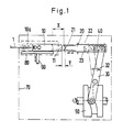
- Fig. 1 the projectile can be seen in its standstill position after braking in the catch brake 80.
- the catch brake 80 here indicated schematically only by dashed lines, has the task of braking the projectile after entering the catch mechanism 70 within a weaving path that is as constant as possible, with a safety distance Y between the projectile head 11 and the push-back head 21 being maintained.
- the return pusher head 21 forms the part of the return pusher 20 facing the projectile 1, which is driven by the cam drum 50 via the return pusher tab 40 and the return pusher lever 30. While the cam drum 50 is continuously driven by the main drive of the weaving machine, the push-back lever 30 executes a discontinuous pivoting movement according to arrow 32 during the push-back process.
- the return pusher 20 slides back and forth horizontally around the dimension X between the guides 22 and 23 and pushes the projectile 1 back into the position indicated by dash-dotted lines, in which it is pushed out of the catch mechanism 70 by the ejector 60.
- Fig. 2 are above the angle of rotation of the main drive of the loom, the return slide path and the return slide speed according to the prior art with dashed lines and according to the invention with solid lines Lines shown.
- the amount of the return slide speed is shown, so that the return stroke of the return slide stroke results in up to approximately 350 °.
- the properties of the return slide drive according to the invention can be seen particularly well in relation to those of a return slide according to the prior art in the speed diagram in FIG. 2 below.
- the reversal point of the push back has been moved from approx. 353 ° to 358 ° for a push back according to the invention.
- the total movement time of a back slide according to the invention measured on the angle of rotation of the weaving machine, extends over 65 ° compared to 55 ° for a back slide according to the prior art.
- the reversal point of the back slide has been moved from approx. 330 ° to approx.
- the acceleration time during which the push-back speed increases is at least 60% of the total movement time during a push-back stroke.
- the catching brake of a projectile weaving machine is generally set so that the minimum distance between the projectile 1 and the push-back head 21 is not less than 10 mm. It can be seen from the path diagram of the return pusher in the upper part of FIG. 2 that in a drive of the return pusher designed according to the invention, the contact between the return pusher head and the projectile takes place from approximately 320 °. In the lower part of FIG. 2, it can be seen from the speed diagram of the pushback device that from the earliest point of contact between the pushback head and the projectile, which is possible after covering a distance of 10 mm of the pushback device, there are already considerable speed differences between a drive according to the prior art and occur a drive according to the invention.
Landscapes
- Engineering & Computer Science (AREA)
- Textile Engineering (AREA)
- Looms (AREA)
Priority Applications (3)
| Application Number | Priority Date | Filing Date | Title |
|---|---|---|---|
| EP19850810536 EP0222049B1 (fr) | 1985-11-13 | 1985-11-13 | Métier à tisser |
| DE8585810536T DE3563638D1 (en) | 1985-11-13 | 1985-11-13 | Loom |
| JP26949686A JPS62117855A (ja) | 1985-11-13 | 1986-11-12 | 織機のひ戻し装置 |
Applications Claiming Priority (1)
| Application Number | Priority Date | Filing Date | Title |
|---|---|---|---|
| EP19850810536 EP0222049B1 (fr) | 1985-11-13 | 1985-11-13 | Métier à tisser |
Publications (2)
| Publication Number | Publication Date |
|---|---|
| EP0222049A1 true EP0222049A1 (fr) | 1987-05-20 |
| EP0222049B1 EP0222049B1 (fr) | 1988-07-06 |
Family
ID=8194659
Family Applications (1)
| Application Number | Title | Priority Date | Filing Date |
|---|---|---|---|
| EP19850810536 Expired EP0222049B1 (fr) | 1985-11-13 | 1985-11-13 | Métier à tisser |
Country Status (3)
| Country | Link |
|---|---|
| EP (1) | EP0222049B1 (fr) |
| JP (1) | JPS62117855A (fr) |
| DE (1) | DE3563638D1 (fr) |
Citations (3)
| Publication number | Priority date | Publication date | Assignee | Title |
|---|---|---|---|---|
| DE1244076B (de) * | 1961-06-14 | 1967-07-06 | Sulzer Ag | Webmaschine mit Greiferschuetzen |
| FR2393094A1 (fr) * | 1977-06-01 | 1978-12-29 | Sulzer Ag | Dispositif recepteur de l'organe d'insertion de la trame d'une machine a tisser |
| DE3222393A1 (de) * | 1982-05-07 | 1983-11-17 | Gebrüder Sulzer AG, 8401 Winterthur | Verfahren zum betrieb des fangwerkes von greiferprojektil-webmaschinen |
-
1985
- 1985-11-13 EP EP19850810536 patent/EP0222049B1/fr not_active Expired
- 1985-11-13 DE DE8585810536T patent/DE3563638D1/de not_active Expired
-
1986
- 1986-11-12 JP JP26949686A patent/JPS62117855A/ja active Pending
Patent Citations (3)
| Publication number | Priority date | Publication date | Assignee | Title |
|---|---|---|---|---|
| DE1244076B (de) * | 1961-06-14 | 1967-07-06 | Sulzer Ag | Webmaschine mit Greiferschuetzen |
| FR2393094A1 (fr) * | 1977-06-01 | 1978-12-29 | Sulzer Ag | Dispositif recepteur de l'organe d'insertion de la trame d'une machine a tisser |
| DE3222393A1 (de) * | 1982-05-07 | 1983-11-17 | Gebrüder Sulzer AG, 8401 Winterthur | Verfahren zum betrieb des fangwerkes von greiferprojektil-webmaschinen |
Also Published As
| Publication number | Publication date |
|---|---|
| EP0222049B1 (fr) | 1988-07-06 |
| DE3563638D1 (en) | 1988-08-11 |
| JPS62117855A (ja) | 1987-05-29 |
Similar Documents
| Publication | Publication Date | Title |
|---|---|---|
| CH661538A5 (de) | Vorrichtung zum entfernen von schussfaeden aus einer webmaschine. | |
| DE1961689B2 (de) | Schussfadeneintragvorrichtung | |
| DE1535520A1 (de) | Webverfahren mit umlaufenden Greifschuetzen und Webstuhl zu dessen Durchfuehrung | |
| EP0222049B1 (fr) | Métier à tisser | |
| CH669802A5 (fr) | ||
| DE1710353B1 (de) | Verfahren zur Bildung einer Gewebeleiste bei auf Greiferwebmaschinen hergestellten Geweben und Vorrichtung zur Durchfuehrung des Verfahrens | |
| DE3812960A1 (de) | Greiferwebmaschine | |
| DE2740881C3 (de) | Fangvorrichtung für das Schußeinrtagsorgan einer Webmaschine | |
| DE1535414B1 (de) | Verfahren zum Bilden von verduennten Einlegekanten beim Herstellen von Geweben auf Webmaschinen mit Entnahme des Schussfadens von ortsfesten Vorratsspulen und Vorrichtung zur Durchfuehrung des Verfahrens | |
| EP0109607B1 (fr) | Métier à tisser à plat avec une navette à pince circulant dans un circuit fermé | |
| EP0053217B1 (fr) | Lamelle de guidage pour la formation du canal de guidage dans un métier à tisser | |
| DE660810C (de) | Vorrichtung zur UEbergabe des Schussfadens an den Greiferschuetzen bei Webstuehlen mit feststehenden Schussspulen | |
| DE1941404A1 (de) | Verfahren zur Beendigung der Durchschlagphase eines Greifers auf Greiferwebstuehlen,zur Ausfaedelung des durch ihn in das Fach eingetragenen Schussfadens und zum unmittelbar nachfolgenden Einziehen eines neuen Schussfadens | |
| EP0053216B1 (fr) | Buse de soufflage auxiliaire pour métier à tisser à jet d'air | |
| DE2207099A1 (de) | Fadenklemme fuer textilmaschinen | |
| CH655140A5 (de) | Verfahren zum betrieb des fangwerkes von greiferprojektil-webmaschinen. | |
| DE2654052A1 (de) | Verfahren und vorrichtung zur herstellung eines gewebes | |
| DE869322C (de) | Verfahren zum Weben auf Greiferwebmaschinen und Webmaschine zur Ausfuehrung des Verfahrens | |
| EP0340165B1 (fr) | Métier à tisser avec dispositif de formation de lisière mécanique | |
| DE3308674A1 (de) | Muenzsortiervorrichtung | |
| DE1535346C (de) | Vorrichtung zum Eintragen von verschiedenartigen Schußfäden bei Webmaschinen mit Schußfadeneintragvorrichtungen zur Entnahme der Schußfäden von außerhalb des Faches angeordneten Spulen | |
| DE1272844B (de) | Verfahren zum Herstellen eines Gewebes mit abgeschnittenen Schussfaeden und einer von umgelegten Schussfadenenden gebildeten Leiste | |
| DE930826C (de) | Verfahren, Vorrichtung und Nadel zum selbsttaetigen Umhaengen des Doppelrandes auf der flachen Kulierwirkmaschine | |
| DE3242121A1 (de) | Webmaschine fuer siebe und filze zur ausruestung von papiermaschinen und dergleichen | |
| DE3908559C2 (fr) |
Legal Events
| Date | Code | Title | Description |
|---|---|---|---|
| PUAI | Public reference made under article 153(3) epc to a published international application that has entered the european phase |
Free format text: ORIGINAL CODE: 0009012 |
|
| 17P | Request for examination filed |
Effective date: 19851115 |
|
| AK | Designated contracting states |
Kind code of ref document: A1 Designated state(s): AT BE CH DE FR GB IT LI LU NL SE |
|
| RBV | Designated contracting states (corrected) |
Designated state(s): BE CH DE FR GB IT LI |
|
| 17Q | First examination report despatched |
Effective date: 19871028 |
|
| ITF | It: translation for a ep patent filed | ||
| GRAA | (expected) grant |
Free format text: ORIGINAL CODE: 0009210 |
|
| AK | Designated contracting states |
Kind code of ref document: B1 Designated state(s): BE CH DE FR GB IT LI |
|
| GBT | Gb: translation of ep patent filed (gb section 77(6)(a)/1977) | ||
| REF | Corresponds to: |
Ref document number: 3563638 Country of ref document: DE Date of ref document: 19880811 |
|
| ET | Fr: translation filed | ||
| PGFP | Annual fee paid to national office [announced via postgrant information from national office to epo] |
Ref country code: DE Payment date: 19881230 Year of fee payment: 4 |
|
| PLBE | No opposition filed within time limit |
Free format text: ORIGINAL CODE: 0009261 |
|
| STAA | Information on the status of an ep patent application or granted ep patent |
Free format text: STATUS: NO OPPOSITION FILED WITHIN TIME LIMIT |
|
| 26N | No opposition filed | ||
| PG25 | Lapsed in a contracting state [announced via postgrant information from national office to epo] |
Ref country code: GB Effective date: 19891113 |
|
| PG25 | Lapsed in a contracting state [announced via postgrant information from national office to epo] |
Ref country code: LI Effective date: 19891130 Ref country code: CH Effective date: 19891130 Ref country code: BE Effective date: 19891130 |
|
| BERE | Be: lapsed |
Owner name: GEBRUDER SULZER A.G. Effective date: 19891130 |
|
| GBPC | Gb: european patent ceased through non-payment of renewal fee | ||
| PG25 | Lapsed in a contracting state [announced via postgrant information from national office to epo] |
Ref country code: FR Effective date: 19900731 |
|
| REG | Reference to a national code |
Ref country code: CH Ref legal event code: PL |
|
| PG25 | Lapsed in a contracting state [announced via postgrant information from national office to epo] |
Ref country code: DE Effective date: 19900801 |
|
| REG | Reference to a national code |
Ref country code: FR Ref legal event code: ST |