EP0222063A2 - Vorrichtung zum Austrag von Schüttgut aus einer Halde - Google Patents
Vorrichtung zum Austrag von Schüttgut aus einer Halde Download PDFInfo
- Publication number
- EP0222063A2 EP0222063A2 EP86110246A EP86110246A EP0222063A2 EP 0222063 A2 EP0222063 A2 EP 0222063A2 EP 86110246 A EP86110246 A EP 86110246A EP 86110246 A EP86110246 A EP 86110246A EP 0222063 A2 EP0222063 A2 EP 0222063A2
- Authority
- EP
- European Patent Office
- Prior art keywords
- conveyor
- elements
- trough
- stockpile
- carrying
- Prior art date
- Legal status (The legal status is an assumption and is not a legal conclusion. Google has not performed a legal analysis and makes no representation as to the accuracy of the status listed.)
- Granted
Links
- 239000013590 bulk material Substances 0.000 title claims abstract description 18
- 239000000463 material Substances 0.000 claims abstract description 23
- 230000000295 complement effect Effects 0.000 claims description 2
- 230000007423 decrease Effects 0.000 claims description 2
- 238000010276 construction Methods 0.000 abstract description 2
- 238000007599 discharging Methods 0.000 abstract description 2
- 230000006378 damage Effects 0.000 description 1
- 230000001419 dependent effect Effects 0.000 description 1
Images


Classifications
-
- B—PERFORMING OPERATIONS; TRANSPORTING
- B65—CONVEYING; PACKING; STORING; HANDLING THIN OR FILAMENTARY MATERIAL
- B65G—TRANSPORT OR STORAGE DEVICES, e.g. CONVEYORS FOR LOADING OR TIPPING, SHOP CONVEYOR SYSTEMS OR PNEUMATIC TUBE CONVEYORS
- B65G65/00—Loading or unloading
- B65G65/02—Loading or unloading machines comprising essentially a conveyor for moving the loads associated with a device for picking-up the loads
- B65G65/06—Loading or unloading machines comprising essentially a conveyor for moving the loads associated with a device for picking-up the loads with endless scraping or elevating pick-up conveyors
Definitions
- the invention relates to a device according to the preamble of claim 1.
- scraper conveyors have often been used to discharge bulk material from a stockpile, in which the conveying elements are formed by scraper blades, which pick up the material trickling down from the tip of the stockpile and transport it out of the stockpile area.
- the bulk material is pushed and rolled in front of the scraper, which causes grain destruction in the case of sensitive goods.
- Another disadvantage is the considerable energy requirement, which is primarily due to the high friction work.
- the invention is therefore based on the object of designing a device of the type required in the preamble of claim 1 in such a way that a particularly gentle transport of the bulk material is ensured, while at the same time requiring little energy.
- the bulk material trickling down from the heap of embankment passes through the material inlet openings provided in the side wall of the conveying elements into the elongate carrying trough formed by the conveying elements and is distributed over the cross section of the carrying trough when the conveyor is moved by the stationary guide elements a closed bulk bed has formed in the conveyor at the end. After the bulk material has left the area of a guide element, it is at rest and is no longer moved relative to the conveyor. This ensures special grain protection when transporting goods.
- the greatly reduced friction within the bulk material according to the invention results in a substantial reduction in the energy requirement. It is also advantageous that - compared to a known scraper conveyor - a much larger amount of bulk material can be transported with the same construction volume.
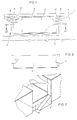
- the device illustrated in the drawing for discharging bulk material from a heap 1 contains a conveyor 2 which rotates endlessly parallel to a heap side.
- This conveyor has a plurality of conveying elements 3, which are U-shaped in cross-section and complement each other to form an elongated carrying trough.
- the side wall of the conveying elements 3 facing the heap 1 is provided with good inlet openings 4.
- plow-like lifting elements 5 are provided on the outside of the side wall of the conveying elements 3 facing the heap 1, which lift the good they have grasped to the level of the bottom of the carrying trough and convey them through the good entry openings 4 into the interior of the carrying trough.
- Guide elements 6, which are arranged in a fixed manner from above, engage in the carrying trough and serve to distribute material well over the cross section of the carrying trough.
- the guide elements 6 are fastened to a support system 7, on which the conveyor elements 3 are suspended via support rollers 8, 9 and are guided over guide rollers 10.
- the connection of the individual conveyor elements 3 is ensured by two link chains 11, 12.
- the width of the conveyor elements 3 (transverse to the direction of movement - arrow 13 - of the conveyor) is a multiple of the length of the conveyor elements 3 (in the direction of movement of the conveyor).
- the product inlet openings 4 extend to the bottom of the support trough formed by the conveying elements 3.
- the plow-like lifting elements 5 extend at least to the lower edge of the product entry openings 4 (cf. FIG. 3).
- the length of the guiding elements 6 which follow one another in the conveying direction and are designed as sheets decreases (cf. FIG. 4).
- the angle of attack of the guide elements 6 with respect to the direction of movement (arrow 13) of the conveyor is expediently adjustable.
- the bulk material trickling down from the slope of the stockpile 1 passes through the product inlet openings 4 into the carrying trough formed by the conveying elements 3 and is distributed over the cross section of the carrying trough when the conveyor 2 is moved by the stationary guide elements 6 in the manner shown in FIG .
- the individual guide elements 6 steer the bulk material more or less onto the side of the conveyor facing away from the stockpile.
- the guide elements 6 are staggered so that a closed bulk bed has formed at the end of the discharge device in the carrying trough of the conveyor 2. As can be seen from FIG. 4, the bulk material remains at rest as soon as it has left the respective guide element 6.
- the plow-like lifting elements 5 clear the path of the conveyor in the direction of the stockpile. You lift the bulk material in the way and convey it through the material inlet openings 4 into the interior of the carrying trough.
- the angle of attack of the guide elements 6 with respect to the direction of movement of the conveyor 2 can be varied depending on the type of bulk material and conveying speed. Furthermore, the guide elements can optionally on a material feed from the one or the other long side of the conveyor can be adjusted so that they can be aligned with the new entry direction when changing the stockpile (entry of the material from the opposite side, for example with longitudinal mixing beds).
- both side walls of the conveying elements 3 are expediently provided with material entry openings 4.
- These good inlet openings 4 can be designed to be closable.
- the material inlet openings 4 can end above the bottom of the support trough formed by the conveying elements 3 and to extend to a side rim 14 delimiting the support trough in the region of the material inlet opening 4 (see FIG. 5).
- the bulk material can be dammed up in the carrying trough of the conveyor 2 up to the height of the side board 14, the plow-like lifting elements 5 also reaching here at least to the lower edge of the product inlet openings 4.
Landscapes
- Engineering & Computer Science (AREA)
- Mechanical Engineering (AREA)
- Filling Or Emptying Of Bunkers, Hoppers, And Tanks (AREA)
- Discharge Of Articles From Conveyors (AREA)
- Structure Of Belt Conveyors (AREA)
Abstract
Description
- Die Erfindung betrifft eine Vorrichtung entsprechend dem Oberbegriff des Anspruches 1.
- Zum Austrag von Schüttgut aus einer Halde werden bisher vielfach Kratzerförderer verwendet, bei denen die Förderelemente durch Kratzschaufeln gebildet werden, die das vom Haldenanschnitt herabrieselnde Material aufnehmen und aus dem Haldenbereich transportieren. Das Schüttgut wird hierbei vor der Kratzschaufel her geschoben und gewälzt, was bei empfindlichem Gut eine Kornzerstörung mit sich bringt. Nachteilig ist weiterhin der vor allem durch die hohe Reibungsarbeit bedingte beträchtliche Energiebedarf.
- Der Erfindung liegt daher die Aufgabe zugrunde, eine Vorrichtung der im Oberbegriff des Anspruches 1 vorausgesetzten Art so auszubilden, daß - bei zugleich geringem Energiebedarf - ein besonders schonender Transport des Schüttgutes gewährleistet ist.
- Diese Aufgabe wird erfindungsgemäß durch die kennzeichnenden Merkmale des Anspruches 1 gelöst.
- Zweckmäßige Ausgestaltungen der Erfindung sind Gegenstand der Unteransprüche.
- Bei der erfindungsgemäßen Vorrichtung gelangt das von der Haldenböschung herabrieselnde Schüttgut durch die in der Seitenwand der Förderelemente vorgesehenen Guteintrittsöffnungen in die von den Förderelementen gebildete, langgestreckte Tragmulde und wird bei der Bewegung des Förderers durch die ortsfest angeordneten Leitelemente über den Querschnitt der Tragmulde verteilt, so daß sich am Ende ein geschlossenes Schüttgutbett im Förderer gebildet hat. Nachdem das Schüttgut den Bereich eines Leitelementes verlassen hat, befindet es sich in Ruhe und wird relativ zum Förderer nicht mehr bewegt. Dadurch ist eine besondere Kornschonung beim Guttransport gewährleistet.
- Durch die erfindungsgemäß stark verringerte Reibung innerhalb des Schüttgutes ergibt sich eine wesentliche Senkung des Energiebedarfes. Vorteilhaft ist ferner, daß - im Vergleich zu einem bekannten Kratzerförderer - bei gleichem Bauvolumen eine wesentlich größere Menge Schüttgut transportiert werden kann.
- Ein Ausführungsbeispiel der Erfindung ist in der Zeichnung veranschaulicht. Es zeigen
- Fig.1 einen Querschnitt durch eine erfindungsgemäße Vorrichtung,
- Fig.2 eine Aufsicht auf ein Förderelement des Förderers,
- Fig.3 eine Perspektivansicht von zwei Förderelementen,
- Fig.4 einen Horizontalschnitt durch den Förderer (längs der Linie IV-IV der Fig.1),
- Fig.5 ein Detail einer Variante.
- Die in der Zeichnung veranschaulichte Vorrichtung zum Austrag von Schüttgut aus einer Halde 1 enthält einen Förderer 2, der parallel zu einer Haldenseite endlos umläuft.
- Dieser Förderer besitzt eine Vielzahl von Förderelementen 3, die im Querschnitt U-förmig ausgebildet sind und sich zu einer langgestreckten Tragmulde ergänzen.
- Die der Halde 1 zugekehrte Seitenwand der Förderelemente 3 ist mit Guteintrittsöffnungen 4 versehen. Im Bereich dieser Guteintrittsöffnungen 4 sind an der Außenseite der der Halde 1 zugekehrten Seitenwand der Förderelemente 3 pflugartige Hubelemente 5 vorgesehen, die das von ihnen erfaßte Gut auf die Höhe des Bodens der Tragmulde anheben und durch die Guteintrittsöffnungen 4 in das Innere der Tragmulde befördern.
- In die Tragmulde greifen von oben ortsfest angeordnete Leitelemente 6 ein, die zur Gutverteilung über den Querschnitt der Tragmulde dienen.
- Die Leitelemente 6 sind an einem Tragsystem 7 befestigt, an dem die Förderelemente 3 über Tragrollen 8, 9 aufgehängt und über Führungsrollen 10 geführt sind. Der Verbund der einzelnen Förderelemente 3 wird durch zwei Laschenketten 11, 12 gewährleistet.
- Die Breite der Förderelemente 3 (quer zur Bewegungsrichtung - Pfeil 13 - des Förderers) beträgt ein Mehrfaches der Länge der Förderelemente 3 (in Bewegungsrichtung des Förderers).
- Bei dem in den Fig.1 bis 4 dargestellten Ausführungsbeispiel reichen die Guteintrittsöffnungen 4 bis zum Boden der von den Förderelementen 3 gebildeten Tragmulde. Die pflugartigen Hubelemente 5 reichen mindestens bis zum unteren Rand der Guteintrittsöffnungen 4 (vgl. Fig.3).
- Die Länge der in Förderichtung aufeinanderfolgenden, als Bleche ausgebildeten Leitelemente 6 nimmt ab (vgl. Fig.4). Der Anstellwinkel der Leitelemente 6 gegenüber der Bewegungsrichtung (Pfeil 13) des Förderers ist zweckmäßig einstellbar.
- Die Funktion der erfindungsgemäßen Vorrichtung ist damit wie folgt:
- Das von der Böschung der Halde 1 herabrieselnde Schüttgut gelangt durch die Guteintrittsöffnungen 4 in die von den Förderelementen 3 gebildete Tragmulde und wird bei der Bewegung des Förderers 2 durch die ortsfest angeordneten Leitelemente 6 in der aus Fig.4 ersichtlichen Weise über den Querschnitt der Tragmulde verteilt. Die einzelnen Leitelemente 6 lenken das Schüttgut mehr oder weniger auf die der Halde abgewandte Seite des Förderers. Die Leitelemente 6 sind dabei so gestaffelt, daß sich am Ende der Austragsvorrichtung in der Tragmulde des Förderers 2 ein geschlossenes Schüttgutbett gebildet hat. Wie aus Fig.4 hervorgeht, bleibt das Schüttgut in Ruhe, sobald es das jeweilige Leitelement 6 verlassen hat.
- Die pflugartigen Hubelemente 5 räumen den Weg des Förderers in Haldenrichtung frei. Sie heben das im Wege befindliche Schüttgut an und befördern es durch die Guteintrittsöffnungen 4 in das Innere der Tragmulde.
- Der Anstellwinkel der Leitelemente 6 gegenüber der Bewegungsrichtung des Förderers 2 kann je nach Art des Schüttgutes und Fördergeschwindigkeit variiert werden. Ferner können die Leitelemente wahlweise auf eine Gutzuführung von der einen oder anderen Längsseite des Förderers einstellbar sein, so daß sie bei Haldenwechsel (Eintrag des Gutes von der gegenüberliegenden Seite, beispielsweise bei Längsmischbetten) auf die neue Eintragsrichtung ausgerichtet werden können.
- In einem solchen Falle werden zweckmäßig beide Seitenwände der Förderelemente 3 mit Guteintrittsöffnungen 4 versehen werden. Diese Guteintrittsöffnungen 4 können verschließbar ausgebildet werden.
- Es ist ferner möglich, die Guteintrittsöffnungen 4 oberhalb des Bodens der von den Förderelementen 3 gebildeten Tragmulde enden und bis zu einem die Tragmulde im Bereich der Guteintrittsöffnung 4 begrenzenden Seitenbord 14 reichen zu lassen (vgl. Fig.5). In diesem Falle kann das Schüttgut in der Tragmulde des Förderers 2 bis zur Höhe des Seitenbords 14 aufgestaut werden, wobei auch hier die pflugartigen Hubelemente 5 mindestens bis zum unteren Rand der Guteintrittsöffnungen 4 reichen.
Claims (11)
gekennzeichnet durch folgende Merkmale:
Applications Claiming Priority (2)
| Application Number | Priority Date | Filing Date | Title |
|---|---|---|---|
| DE19853540391 DE3540391A1 (de) | 1985-11-14 | 1985-11-14 | Vorrichtung zum austrag von schuettgut aus einer halde |
| DE3540391 | 1985-11-14 |
Publications (3)
| Publication Number | Publication Date |
|---|---|
| EP0222063A2 true EP0222063A2 (de) | 1987-05-20 |
| EP0222063A3 EP0222063A3 (en) | 1989-03-08 |
| EP0222063B1 EP0222063B1 (de) | 1990-10-31 |
Family
ID=6285970
Family Applications (1)
| Application Number | Title | Priority Date | Filing Date |
|---|---|---|---|
| EP86110246A Expired - Lifetime EP0222063B1 (de) | 1985-11-14 | 1986-07-25 | Vorrichtung zum Austrag von Schüttgut aus einer Halde |
Country Status (2)
| Country | Link |
|---|---|
| EP (1) | EP0222063B1 (de) |
| DE (2) | DE3540391A1 (de) |
Cited By (3)
| Publication number | Priority date | Publication date | Assignee | Title |
|---|---|---|---|---|
| GB2187428B (en) * | 1986-01-31 | 1989-11-01 | Orenstein & Koppel Ag | Device for clearing stockpiles of bulk materials |
| US5199549A (en) * | 1991-07-23 | 1993-04-06 | Krupp Polysius Ag | Scraper conveyor for loose bulk material |
| CN105293093A (zh) * | 2015-10-21 | 2016-02-03 | 广东省现代农业装备研究所 | 一种高床养殖垫料翻堆装置 |
Families Citing this family (1)
| Publication number | Priority date | Publication date | Assignee | Title |
|---|---|---|---|---|
| DE3800926A1 (de) * | 1988-01-14 | 1989-07-27 | Krupp Polysius Ag | Foerdereinrichtung fuer schuettgut |
Family Cites Families (4)
| Publication number | Priority date | Publication date | Assignee | Title |
|---|---|---|---|---|
| BE509415A (de) * | ||||
| DE560438C (de) * | 1930-11-21 | 1932-10-03 | Vereinigungsgesellschaft Rhein | Raeummaschine |
| DE2828233C3 (de) * | 1978-06-28 | 1984-06-20 | PHB Weserhütte AG, 5000 Köln | Gerät zum Entspeichern von Schüttguthalden |
| DE2846789C2 (de) * | 1978-10-27 | 1986-04-17 | Gustav Schade Maschinenfabrik Gmbh & Co, 4600 Dortmund | Entspeicherungsgerät für das Abräumen von Schüttguthalden |
-
1985
- 1985-11-14 DE DE19853540391 patent/DE3540391A1/de not_active Withdrawn
-
1986
- 1986-07-25 EP EP86110246A patent/EP0222063B1/de not_active Expired - Lifetime
- 1986-07-25 DE DE8686110246T patent/DE3675335D1/de not_active Expired - Fee Related
Cited By (3)
| Publication number | Priority date | Publication date | Assignee | Title |
|---|---|---|---|---|
| GB2187428B (en) * | 1986-01-31 | 1989-11-01 | Orenstein & Koppel Ag | Device for clearing stockpiles of bulk materials |
| US5199549A (en) * | 1991-07-23 | 1993-04-06 | Krupp Polysius Ag | Scraper conveyor for loose bulk material |
| CN105293093A (zh) * | 2015-10-21 | 2016-02-03 | 广东省现代农业装备研究所 | 一种高床养殖垫料翻堆装置 |
Also Published As
| Publication number | Publication date |
|---|---|
| DE3675335D1 (de) | 1990-12-06 |
| EP0222063B1 (de) | 1990-10-31 |
| EP0222063A3 (en) | 1989-03-08 |
| DE3540391A1 (de) | 1987-05-21 |
Similar Documents
| Publication | Publication Date | Title |
|---|---|---|
| EP0230612B1 (de) | Seitenkratzer für Schüttguthalde | |
| DE2731281C2 (de) | Fördervorrichtung mit einem Fördergut in variabler Menge | |
| DE4303413A1 (de) | Beschickungsvorrichtung für eine Palettiervorrichtung | |
| DE2047131A1 (de) | Richtungswandler fur Behalterfbr dereinnchtungen | |
| EP0222063B1 (de) | Vorrichtung zum Austrag von Schüttgut aus einer Halde | |
| DE3404024A1 (de) | Vorrichtung zur gleichmaessigen beschickung eines foerderbandes fuer granulierte schlacke | |
| EP0434995B1 (de) | Silo mit einer Austragvorrichtung | |
| DE1031220B (de) | Vorrichtung zum Austragen von Holzspaenen u. dgl. aus einem Bunker | |
| DE2802188C3 (de) | Vorrichtung zum Ordnen von schweren metallischen Werkstücken | |
| DE2846789C2 (de) | Entspeicherungsgerät für das Abräumen von Schüttguthalden | |
| DE847878C (de) | Vorrichtung zum Entleeren von Foerdergut aus Schwingfoerderrinnen an beliebiger Stelle | |
| DE2834782A1 (de) | Silagefraeser mit vorratsbehaelter | |
| DE2649835C3 (de) | Schneckenförderer für körniges Material, wie Getreide | |
| DE3881704T2 (de) | Anordnung zum befördern von massengut. | |
| AT223535B (de) | Fördereinrichtung | |
| DE3601292A1 (de) | Kratzerfoerderer | |
| DE3207287C2 (de) | ||
| DE2461756A1 (de) | Foerdervorrichtung fuer in bruchstuecken vorliegendes gut aus einem vorratslager | |
| DE3524778C1 (de) | Vorrichtung zum Aufnehmen und Abfoerdern von in Haufwerken gelagerten Feldfruechten | |
| DE968657C (de) | Vorrichtung zum Verteilen und Auseinanderziehen von in Haufen anfallendem Blattgut, insbesondere Tabakblaettern | |
| DE9014270U1 (de) | Silo mit einer Austragvorrichtung | |
| DE726579C (de) | Zufuehrungsvorrichtung fuer Foerderschnecken mit sich gegenlaeufig drehenden Zufuehrungsorganen, deren Aussenumfaenge sich ueberschneiden | |
| DE2314528A1 (de) | Vorrichtung zur regulierung der schichthoehe eines foerdergutstromes auf einem bandfoerderer | |
| AT410544B (de) | Einrichtung zum umsetzen von auf einem kompostierfeld gelagertem, verrottbarem gut | |
| DE3021308A1 (de) | Vorrichtung zum raeumen einer halde |
Legal Events
| Date | Code | Title | Description |
|---|---|---|---|
| PUAI | Public reference made under article 153(3) epc to a published international application that has entered the european phase |
Free format text: ORIGINAL CODE: 0009012 |
|
| AK | Designated contracting states |
Kind code of ref document: A2 Designated state(s): BE DE FR GB IT |
|
| PUAL | Search report despatched |
Free format text: ORIGINAL CODE: 0009013 |
|
| RHK1 | Main classification (correction) |
Ipc: B65G 65/28 |
|
| AK | Designated contracting states |
Kind code of ref document: A3 Designated state(s): BE DE FR GB IT |
|
| 17P | Request for examination filed |
Effective date: 19890908 |
|
| 17Q | First examination report despatched |
Effective date: 19891204 |
|
| GRAA | (expected) grant |
Free format text: ORIGINAL CODE: 0009210 |
|
| AK | Designated contracting states |
Kind code of ref document: B1 Designated state(s): BE DE FR GB IT |
|
| GBT | Gb: translation of ep patent filed (gb section 77(6)(a)/1977) | ||
| REF | Corresponds to: |
Ref document number: 3675335 Country of ref document: DE Date of ref document: 19901206 |
|
| ET | Fr: translation filed | ||
| ITF | It: translation for a ep patent filed | ||
| PLBE | No opposition filed within time limit |
Free format text: ORIGINAL CODE: 0009261 |
|
| STAA | Information on the status of an ep patent application or granted ep patent |
Free format text: STATUS: NO OPPOSITION FILED WITHIN TIME LIMIT |
|
| 26N | No opposition filed | ||
| ITTA | It: last paid annual fee | ||
| PGFP | Annual fee paid to national office [announced via postgrant information from national office to epo] |
Ref country code: FR Payment date: 19940609 Year of fee payment: 9 |
|
| PGFP | Annual fee paid to national office [announced via postgrant information from national office to epo] |
Ref country code: GB Payment date: 19940620 Year of fee payment: 9 Ref country code: BE Payment date: 19940620 Year of fee payment: 9 |
|
| PGFP | Annual fee paid to national office [announced via postgrant information from national office to epo] |
Ref country code: DE Payment date: 19940712 Year of fee payment: 9 |
|
| PG25 | Lapsed in a contracting state [announced via postgrant information from national office to epo] |
Ref country code: GB Effective date: 19950725 |
|
| PG25 | Lapsed in a contracting state [announced via postgrant information from national office to epo] |
Ref country code: BE Effective date: 19950731 |
|
| BERE | Be: lapsed |
Owner name: KRUPP POLYSIUS A.G. Effective date: 19950731 |
|
| GBPC | Gb: european patent ceased through non-payment of renewal fee |
Effective date: 19950725 |
|
| PG25 | Lapsed in a contracting state [announced via postgrant information from national office to epo] |
Ref country code: DE Effective date: 19960402 |
|
| PG25 | Lapsed in a contracting state [announced via postgrant information from national office to epo] |
Ref country code: FR Effective date: 19960430 |
|
| REG | Reference to a national code |
Ref country code: FR Ref legal event code: ST |
|
| REG | Reference to a national code |
Ref country code: FR Ref legal event code: ST |
|
| REG | Reference to a national code |
Ref country code: FR Ref legal event code: ST |
|
| PG25 | Lapsed in a contracting state [announced via postgrant information from national office to epo] |
Ref country code: IT Free format text: LAPSE BECAUSE OF NON-PAYMENT OF DUE FEES;WARNING: LAPSES OF ITALIAN PATENTS WITH EFFECTIVE DATE BEFORE 2007 MAY HAVE OCCURRED AT ANY TIME BEFORE 2007. THE CORRECT EFFECTIVE DATE MAY BE DIFFERENT FROM THE ONE RECORDED. Effective date: 20050725 |