EP0222077B1 - Dispositif de mesure de la vitesse de rotation - Google Patents
Dispositif de mesure de la vitesse de rotation Download PDFInfo
- Publication number
- EP0222077B1 EP0222077B1 EP86111253A EP86111253A EP0222077B1 EP 0222077 B1 EP0222077 B1 EP 0222077B1 EP 86111253 A EP86111253 A EP 86111253A EP 86111253 A EP86111253 A EP 86111253A EP 0222077 B1 EP0222077 B1 EP 0222077B1
- Authority
- EP
- European Patent Office
- Prior art keywords
- modulation
- frequencies
- signal
- frequency
- maximum
- Prior art date
- Legal status (The legal status is an assumption and is not a legal conclusion. Google has not performed a legal analysis and makes no representation as to the accuracy of the status listed.)
- Expired - Lifetime
Links
- 238000011156 evaluation Methods 0.000 claims description 9
- 239000013307 optical fiber Substances 0.000 claims description 8
- 230000000694 effects Effects 0.000 claims 1
- 230000010363 phase shift Effects 0.000 claims 1
- 238000001514 detection method Methods 0.000 description 7
- 230000035945 sensitivity Effects 0.000 description 5
- 239000000835 fiber Substances 0.000 description 4
- 230000003287 optical effect Effects 0.000 description 2
- 230000001105 regulatory effect Effects 0.000 description 2
- 238000009795 derivation Methods 0.000 description 1
- 238000000034 method Methods 0.000 description 1
- 230000001902 propagating effect Effects 0.000 description 1
- 238000011896 sensitive detection Methods 0.000 description 1
- 230000006641 stabilisation Effects 0.000 description 1
- 238000011105 stabilization Methods 0.000 description 1
Images

Classifications
-
- G—PHYSICS
- G01—MEASURING; TESTING
- G01C—MEASURING DISTANCES, LEVELS OR BEARINGS; SURVEYING; NAVIGATION; GYROSCOPIC INSTRUMENTS; PHOTOGRAMMETRY OR VIDEOGRAMMETRY
- G01C19/00—Gyroscopes; Turn-sensitive devices using vibrating masses; Turn-sensitive devices without moving masses; Measuring angular rate using gyroscopic effects
- G01C19/58—Turn-sensitive devices without moving masses
- G01C19/64—Gyrometers using the Sagnac effect, i.e. rotation-induced shifts between counter-rotating electromagnetic beams
- G01C19/72—Gyrometers using the Sagnac effect, i.e. rotation-induced shifts between counter-rotating electromagnetic beams with counter-rotating light beams in a passive ring, e.g. fibre laser gyrometers
Definitions
- the invention relates to a device for measuring the rotational speed according to the preamble of the main claim.
- DE-OS 3 040 514 describes a phase modulator to which a modulation signal generated by a frequency generator is fed.
- the signal received by the evaluation device via a photodetector is evaluated at two frequencies f i , f 2 , in such a way that this evaluation on the one hand produces a signal which contains the Sagnac phase and on the other hand a control or regulating signal for influencing the frequency generator. This finally affects the modulation signal at the phase modulator.
- the purpose of this measure is to keep the modulation as constant as possible, and thus a more precise signal evaluation.
- control and regulating circuits in particular have a temperature drift, moreover, with this method only one evaluation frequency can be kept at an optimal working point, the amplitude of the 1st order Jessel function only having a very small stroke having.
- DE-OS 3 028 821 discloses a ring interferometer produced with the aid of optical fibers, in which two phase modulators are inserted into the optical path of the optical fiber.
- the two phase modulators are controlled by different generators and generate different phase modulations.
- phase modulator only one phase modulator is provided.
- the signals of two generators are added in an amplifier to a sum signal, which then controls the phase modulator.
- the modulation values (frequencies and stroke) of the two modulation signals used are additionally selected such that the 1st order and 2nd order Bessel functions each have a maximum.
- An embodiment of the invention proposes that both modulation frequencies are superimposed on a single modulation device.
- two modulation devices can be used, each of which is controlled with one frequency.
- the modulation device is constructed, for example, from piezoelectric elements (see EP-A 123 499) but can also consist of integrated optical modulators.
- the invention is explained in more detail below using several exemplary embodiments.
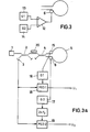
- the fiber gyro shown in Fig. 1 consists of a laser diode 1, the beam splitters 2 and 4 with an intermediate polarizer 20 and a photodiode 3 connected to 2, an optical fiber 5 consisting of at least one turn, a modulator 6 and an evaluation device 7.
- the structure of the Fiber gyro in Fig. 2 is identical to this.
- the evaluation device 7 contains a frequency generator 8, the signal of which is fed to the modulator 6 and a phase-sensitive rectifier circuit 9.
- the modulator 6 consists of a piezoelectric body, around which one or more turns of the optical fiber 5 are wound and which, when activated by the frequency generator 8, modulates the length of the optical fiber 5.
- the phase-sensitive rectifier circuit is supplied with the signal detected by the photodiode and, as a reference signal, with the frequency f m formed by the generator.
- J 1 (2 ⁇ m) in equation (1) must be maximum, which is achieved by setting the modulation stroke 2hub m .
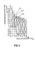
- the x-axis shows the modulation stroke of the modulator and the y-axis the output signal amplitude.
- the B-th order functions are shown. From the figure it can be seen that the maximum of the 1st order Bessel function is at a modulation stroke 2. Of 1.85.
- the simultaneous detection of the fundamental wave signal and the 1st harmonic is of particular interest for various applications (e.g. measuring range expansion, scaling stabilization, etc.).
- a device of this type requires the known structure shown in FIG. 2.
- phase-sensitive rectification is also carried out at twice the generator frequency.
- the rectifier 11 controlled by the reference signal of the frequency doubler 10 forms an output signal U 2 of the first harmonic.
- the modulation stroke 2 ⁇ m is set so that it lies at the maximum of the 1st order Bessel function.
- the modulation stroke would have to take on other values in order to achieve maximum sensitivity and stability; in the illustration shown in FIG. 4, the modulation stroke would be 2 ⁇ m for this case 3.1.
- the modulation stroke in the arrangement according to FIG. 2 cannot be optimized simultaneously for both detection functions. If the modulation stroke was set to the value 1.85 as shown in FIG. 4, the working point A2 would lie on the curve area with a large slope. This has the serious disadvantage that even the smallest changes in the modulation stroke lead to large scaling fluctuations in the corresponding detection function. The sensitivity is also reduced.
- the modulator 6 is therefore controlled in the exemplary embodiment of FIG. 3 via a summing amplifier 12 with two frequencies of the frequency generators 13, 14.
- the required modulation strokes for evaluating the 1st and 2nd order Bessel functions can thus be set independently of one another.
- FIGS. 1 and 2 show a further possibility for setting the modulation values separately.
- the structure of the fiber gyroscope corresponds essentially to that shown in FIGS. 1 and 2.
- a further modulator 15 is arranged in the light path. This modulator 15 is controlled via the frequency generator 16, the modulator 6 via the frequency generator 17.
- the modulators can thus work at different frequencies and with different modulation strokes.
- the signal supplied by the photodiode 3 is fed to the rectifier 18 to form the first output signal U 1 and to the rectifier 19 to form the second output signal U 2 .
- the rectifier 18 is controlled by means of the frequency of the generator 16, that of the rectifier 19 by means of the frequency of the generator 17 via a frequency doubling.
- the output signal U 1 is thus proportional to the 1st order Bessel function with maximum sensitivity.
- the stroke of the generator 17 can be set to a value which allows a maximum amplitude of the output signal U 2 in the 2nd order Bessel function. 4 this means the working point setting in points A1 and A3.
- a further addition can be made by additional modulation frequencies and the evaluation of higher-order Bessel functions; the invention is not limited to the evaluation of two output signals.
Landscapes
- Physics & Mathematics (AREA)
- Engineering & Computer Science (AREA)
- Optics & Photonics (AREA)
- Electromagnetism (AREA)
- Power Engineering (AREA)
- General Physics & Mathematics (AREA)
- Radar, Positioning & Navigation (AREA)
- Remote Sensing (AREA)
- Gyroscopes (AREA)
Claims (6)
caractérisé en ce que les valeurs de modulation formées par la fréquence et l'amplitude d'un signal de modulation sont choisies de manière que la fonction de Bessel d'ordre premier présente un maximum et que les valeurs de modulation de l'autre signal de modulation sont choisies de manière que la fonction de Bessel correspondante du second ordre soit maximale.
Applications Claiming Priority (2)
| Application Number | Priority Date | Filing Date | Title |
|---|---|---|---|
| DE3533695 | 1985-09-21 | ||
| DE19853533695 DE3533695A1 (de) | 1985-09-21 | 1985-09-21 | Verfahren zur messung der drehgeschwindigkeit |
Publications (2)
| Publication Number | Publication Date |
|---|---|
| EP0222077A1 EP0222077A1 (fr) | 1987-05-20 |
| EP0222077B1 true EP0222077B1 (fr) | 1990-11-14 |
Family
ID=6281565
Family Applications (1)
| Application Number | Title | Priority Date | Filing Date |
|---|---|---|---|
| EP86111253A Expired - Lifetime EP0222077B1 (fr) | 1985-09-21 | 1986-08-14 | Dispositif de mesure de la vitesse de rotation |
Country Status (2)
| Country | Link |
|---|---|
| EP (1) | EP0222077B1 (fr) |
| DE (2) | DE3533695A1 (fr) |
Families Citing this family (4)
| Publication number | Priority date | Publication date | Assignee | Title |
|---|---|---|---|---|
| DE3727167A1 (de) * | 1987-08-14 | 1989-02-23 | Teldix Gmbh | Faserkreisel |
| EP0471881A1 (fr) * | 1990-08-24 | 1992-02-26 | SENSOPTIC Optische Sensortechnik AG | Dispositif de mesure d'une grandeur physique |
| WO1992004597A1 (fr) * | 1990-08-31 | 1992-03-19 | Japan Aviation Electronics Industry Limited | Appareil de mesure de la vitesse angulaire par interference optique |
| ATE149674T1 (de) * | 1993-03-05 | 1997-03-15 | Jenoptik Jena Gmbh | Phasenmoduliertes interferometer |
Family Cites Families (9)
| Publication number | Priority date | Publication date | Assignee | Title |
|---|---|---|---|---|
| DE2934794A1 (de) * | 1979-08-29 | 1981-03-19 | Licentia Patent-Verwaltungs-Gmbh, 6000 Frankfurt | Verfahren zur messung absoluter drehungen und anordnung zur durchfuehrung des verfahrens |
| DE3001721A1 (de) * | 1980-01-18 | 1981-07-23 | Licentia Patent-Verwaltungs-Gmbh, 6000 Frankfurt | Verfahren zur messung absoluter drehungen und anordnung zur durchfuehrung des verfahrens |
| DE3028821A1 (de) * | 1980-07-30 | 1982-02-25 | Licentia Patent-Verwaltungs-Gmbh, 6000 Frankfurt | Ringinterferometer |
| DE3040514A1 (de) * | 1980-10-28 | 1982-07-22 | Licentia Patent-Verwaltungs-Gmbh, 6000 Frankfurt | Verfahren und anordnung zur signalauswertung eines lichtleitfaserrotationssensors |
| DE3140110A1 (de) * | 1981-10-09 | 1983-04-28 | Licentia Patent-Verwaltungs-Gmbh, 6000 Frankfurt | "verfahren und anordnung zur messung absoluter drehungen" |
| GB2108652B (en) * | 1981-10-27 | 1985-05-30 | Standard Telephones Cables Ltd | Fibre-optic interferometer gyroscope |
| CA1230663A (fr) * | 1982-04-28 | 1987-12-22 | Kenichi Yoshida | Gyroscope a fibres optiques |
| DE3247013A1 (de) * | 1982-12-18 | 1984-06-20 | Standard Elektrik Lorenz Ag, 7000 Stuttgart | Einrichtung zur messung der rotationsgeschwindigkeit |
| DE3484025D1 (de) * | 1983-04-25 | 1991-03-07 | Univ Leland Stanford Junior | Faseroptischer rotationsdetektor mit erweitertem dynamischem messbereich. |
-
1985
- 1985-09-21 DE DE19853533695 patent/DE3533695A1/de not_active Withdrawn
-
1986
- 1986-08-14 EP EP86111253A patent/EP0222077B1/fr not_active Expired - Lifetime
- 1986-08-14 DE DE8686111253T patent/DE3675629D1/de not_active Expired - Fee Related
Also Published As
| Publication number | Publication date |
|---|---|
| DE3533695A1 (de) | 1987-03-26 |
| DE3675629D1 (de) | 1990-12-20 |
| EP0222077A1 (fr) | 1987-05-20 |
Similar Documents
| Publication | Publication Date | Title |
|---|---|---|
| DE3326555C2 (fr) | ||
| DE69801435T2 (de) | Schwingungsfehlerverminderungsservo für faseroptischen kreisel | |
| DE69924531T2 (de) | Kerreffektkompensation für einen interferometrischen faseroptischen kreisel | |
| EP0074609B1 (fr) | Dispositif de mesure de vitesse de rotation | |
| DE68916785T2 (de) | Gyroskop aus optischer faser mit geschlossener schleife. | |
| DE3805904A1 (de) | Faserkreisel | |
| DE3500633C2 (fr) | ||
| DE69106289T2 (de) | Optischer Faserkreisel. | |
| DE3401640C2 (de) | Einrichtung zur Messung der Drehgeschwindigkeit | |
| EP0670469A1 (fr) | Gyroscope à laser en anneau du type brillouin | |
| DE69115877T2 (de) | Gerät zum messen der winkelgeschwindigkeit durch optische interferenz | |
| DE69102644T2 (de) | Demodulationsreferenzsignalquelle. | |
| EP0602075B1 (fr) | Detecteur optique pour mouvements de rotation | |
| DE2934794A1 (de) | Verfahren zur messung absoluter drehungen und anordnung zur durchfuehrung des verfahrens | |
| DE1614662B2 (de) | Ringlaser | |
| DE3040514A1 (de) | Verfahren und anordnung zur signalauswertung eines lichtleitfaserrotationssensors | |
| DE2936248A1 (de) | Verfahren zum betrieb eines ringinterferometers als rotationssensor | |
| DE69213477T2 (de) | Bestimmung der laufzeit des optischen signals in einem optischen interferometer | |
| EP0222077A1 (fr) | Dispositif de mesure de la vitesse de rotation | |
| EP0164599A1 (fr) | Dispositif pour la mesure de la vitesse de rotation | |
| DE69111080T2 (de) | Amplitudenbestimmung der bias-modulation in einem optischen faserkreisel. | |
| EP0185358B1 (fr) | Dispositif de mesure de la vitesse de rotation | |
| DE68903616T3 (de) | Fiberoptische Messeinrichtung, Gyrometer, Navigations- und Stabilisationssystem. | |
| EP0113890A2 (fr) | Dispositif pour mesurer la vitesse de rotation | |
| EP0172391A2 (fr) | Procédé et dispositif de mesure de la vitesse angulaire avec utilisation de l'effect Sagnac |
Legal Events
| Date | Code | Title | Description |
|---|---|---|---|
| PUAI | Public reference made under article 153(3) epc to a published international application that has entered the european phase |
Free format text: ORIGINAL CODE: 0009012 |
|
| AK | Designated contracting states |
Kind code of ref document: A1 Designated state(s): DE FR GB IT |
|
| 17P | Request for examination filed |
Effective date: 19871029 |
|
| 17Q | First examination report despatched |
Effective date: 19890622 |
|
| GRAA | (expected) grant |
Free format text: ORIGINAL CODE: 0009210 |
|
| ITF | It: translation for a ep patent filed | ||
| AK | Designated contracting states |
Kind code of ref document: B1 Designated state(s): DE FR GB IT |
|
| REF | Corresponds to: |
Ref document number: 3675629 Country of ref document: DE Date of ref document: 19901220 |
|
| ET | Fr: translation filed | ||
| GBT | Gb: translation of ep patent filed (gb section 77(6)(a)/1977) | ||
| ITTA | It: last paid annual fee | ||
| PLBE | No opposition filed within time limit |
Free format text: ORIGINAL CODE: 0009261 |
|
| STAA | Information on the status of an ep patent application or granted ep patent |
Free format text: STATUS: NO OPPOSITION FILED WITHIN TIME LIMIT |
|
| 26N | No opposition filed | ||
| REG | Reference to a national code |
Ref country code: GB Ref legal event code: 746 Effective date: 19930301 |
|
| REG | Reference to a national code |
Ref country code: FR Ref legal event code: DL |
|
| PGFP | Annual fee paid to national office [announced via postgrant information from national office to epo] |
Ref country code: FR Payment date: 19990617 Year of fee payment: 14 |
|
| PGFP | Annual fee paid to national office [announced via postgrant information from national office to epo] |
Ref country code: GB Payment date: 19990625 Year of fee payment: 14 |
|
| PGFP | Annual fee paid to national office [announced via postgrant information from national office to epo] |
Ref country code: DE Payment date: 19990930 Year of fee payment: 14 |
|
| PG25 | Lapsed in a contracting state [announced via postgrant information from national office to epo] |
Ref country code: GB Free format text: LAPSE BECAUSE OF NON-PAYMENT OF DUE FEES Effective date: 20000814 |
|
| GBPC | Gb: european patent ceased through non-payment of renewal fee |
Effective date: 20000814 |
|
| PG25 | Lapsed in a contracting state [announced via postgrant information from national office to epo] |
Ref country code: FR Free format text: LAPSE BECAUSE OF NON-PAYMENT OF DUE FEES Effective date: 20010430 |
|
| PG25 | Lapsed in a contracting state [announced via postgrant information from national office to epo] |
Ref country code: DE Free format text: LAPSE BECAUSE OF NON-PAYMENT OF DUE FEES Effective date: 20010501 |
|
| REG | Reference to a national code |
Ref country code: FR Ref legal event code: ST |
|
| PG25 | Lapsed in a contracting state [announced via postgrant information from national office to epo] |
Ref country code: IT Free format text: LAPSE BECAUSE OF NON-PAYMENT OF DUE FEES;WARNING: LAPSES OF ITALIAN PATENTS WITH EFFECTIVE DATE BEFORE 2007 MAY HAVE OCCURRED AT ANY TIME BEFORE 2007. THE CORRECT EFFECTIVE DATE MAY BE DIFFERENT FROM THE ONE RECORDED. Effective date: 20050814 |