EP0222086A2 - Transformateur de polarisation - Google Patents
Transformateur de polarisation Download PDFInfo
- Publication number
- EP0222086A2 EP0222086A2 EP86111865A EP86111865A EP0222086A2 EP 0222086 A2 EP0222086 A2 EP 0222086A2 EP 86111865 A EP86111865 A EP 86111865A EP 86111865 A EP86111865 A EP 86111865A EP 0222086 A2 EP0222086 A2 EP 0222086A2
- Authority
- EP
- European Patent Office
- Prior art keywords
- polarization converter
- reference system
- waveguide
- wave
- phase
- Prior art date
- Legal status (The legal status is an assumption and is not a legal conclusion. Google has not performed a legal analysis and makes no representation as to the accuracy of the status listed.)
- Granted
Links
Images

Classifications
-
- H—ELECTRICITY
- H01—ELECTRIC ELEMENTS
- H01P—WAVEGUIDES; RESONATORS, LINES, OR OTHER DEVICES OF THE WAVEGUIDE TYPE
- H01P1/00—Auxiliary devices
- H01P1/18—Phase-shifters
- H01P1/185—Phase-shifters using a diode or a gas filled discharge tube
-
- G—PHYSICS
- G03—PHOTOGRAPHY; CINEMATOGRAPHY; ANALOGOUS TECHNIQUES USING WAVES OTHER THAN OPTICAL WAVES; ELECTROGRAPHY; HOLOGRAPHY
- G03F—PHOTOMECHANICAL PRODUCTION OF TEXTURED OR PATTERNED SURFACES, e.g. FOR PRINTING, FOR PROCESSING OF SEMICONDUCTOR DEVICES; MATERIALS THEREFOR; ORIGINALS THEREFOR; APPARATUS SPECIALLY ADAPTED THEREFOR
- G03F7/00—Photomechanical, e.g. photolithographic, production of textured or patterned surfaces, e.g. printing surfaces; Materials therefor, e.g. comprising photoresists; Apparatus specially adapted therefor
- G03F7/004—Photosensitive materials
- G03F7/0048—Photosensitive materials characterised by the solvents or agents facilitating spreading, e.g. tensio-active agents
-
- H—ELECTRICITY
- H01—ELECTRIC ELEMENTS
- H01P—WAVEGUIDES; RESONATORS, LINES, OR OTHER DEVICES OF THE WAVEGUIDE TYPE
- H01P1/00—Auxiliary devices
- H01P1/165—Auxiliary devices for rotating the plane of polarisation
- H01P1/17—Auxiliary devices for rotating the plane of polarisation for producing a continuously rotating polarisation, e.g. circular polarisation
- H01P1/174—Auxiliary devices for rotating the plane of polarisation for producing a continuously rotating polarisation, e.g. circular polarisation using a magnetic element
-
- H—ELECTRICITY
- H01—ELECTRIC ELEMENTS
- H01P—WAVEGUIDES; RESONATORS, LINES, OR OTHER DEVICES OF THE WAVEGUIDE TYPE
- H01P1/00—Auxiliary devices
- H01P1/18—Phase-shifters
- H01P1/19—Phase-shifters using a ferromagnetic device
- H01P1/195—Phase-shifters using a ferromagnetic device having a toroidal shape
Definitions
- the present invention relates to a polarization converter for microwaves, consisting of a waveguide with means arranged therein along its axis, which form a reference system from perpendicular longitudinal sectional planes, in which the orthogonal components of a wave fed into the waveguide undergo phase shifts of different sizes, the reference system being about the longitudinal axis of the waveguide is rotatable.
- Such a polarization converter is known from US Pat. No. 2,607,849.
- a dielectric plate is arranged in a circular waveguide in the direction of wave propagation. This plate represents the above-mentioned orthogonal reference system. This is because a wave component running parallel to the dielectric plate experiences a phase shift dependent on the length of the plate, whereas the wave component oriented perpendicular to it passes through the waveguide almost instantaneously.
- the dielectric plate is rotatably mounted about the waveguide axis, as a result of which the reference system can be aligned at any angle to the plane of polarization of the wave fed in.
- the magnitudes of the orthogonal wave components aligned with the reference system depend on the position of the reference system relative to the polarization plane of the injected wave. so that by twisting the dielectric plate, for example, the ellipticity of a wave can be influenced or its direction of polarization can be changed.
- a polarization converter is used as a variable phase shifter if the polarization converter has 180 ° phase rotation between the orthogonal planes of the reference system and is arranged between 90 ° polarization converters.
- the polarization converter on which US Pat. No. 2,607,849 is based has the advantage that its reference system can be brought into any angular position and thus any desired phase rotation can be imparted to a shaft without restriction.
- the alignment of the reference system takes place in a purely mechanical way by means of the axially rotatably mounted dielectric plate, the angular velocity of the reference system is very narrow.
- the invention is therefore based on the object to provide a polarization converter of the type mentioned, the reference system is realized so that it is set very quickly in any angular position relative to the polarization plane of the injected wave, or that it reaches up to very high angular velocities , continuous rotation can be exposed.
- the polarization converter according to the invention enables, for example, an endlessly rotating phase in a very simple manner slider or to implement a phase or frequency modulator that works with very little loss ( ⁇ 1dB attenuation).
- an electrically controlled polarization converter avoids the disturbing influences on the shaft that usually occur in an arrangement with mechanically movable parts.
- FIGS. 1 front view
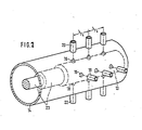
- 2 perspective side view
- This polarization converter consists of a coaxial waveguide, between the inner conductor 13 and outer conductor 14 of which several diodes 15, 16, 17, 18 - preferably capacitance diodes - are arranged.
- the diodes are in contact with the inner conductor 13 and receive their bias voltages via coaxial feed lines 19, 20, 21, 22 which are passed through the outer conductor 14.
- the arrangement of four diodes on the circumference is only one example. A larger number simplifies the continuous rotation of the reference system through the control. However, at least three diodes must be distributed around the circumference, otherwise a rotating reference system cannot be implemented.
- the reference system x ', y' mentioned above is formed by the capacitive impedances of the diodes.
- any desired radial position can also be given to the reference system.
- the reference voltages on which the diode impedances depend can be used to bring the reference system into discrete angular positions or to subject it to continuous rotation with a selectable angular velocity.
- several cross-sectional planes are provided along the waveguide axis at intervals of ⁇ / 4, in which at least three transversely aligned diodes are arranged.
- the number of cross-sectional planes equipped with diodes depends on which phase shift is to be achieved between the wave components propagating in the orthogonal longitudinal sectional planes of the reference system, e.g. a 90 ° or a 180 ° polarization converter is to be realized.
- the inner conductor 13 is provided with gradations 23 at the end (cf. FIG. 2).
- a 180 ° polarization converter 24 of the type described above is used.
- a 90 ° polarization converter 26 or 27 is arranged in front of and behind this variable 180 ° polarization converter. Both 90 ° polarization converters 26 and 27 need only have a rigid reference system.
- Such a polarization converter with a fixed reference system can be realized, for example, in that a Dielectric plate extending wave propagation direction is used (see. US-PS 2 607 849), or that, as shown in Fig. 3, the waveguide 26 and 27 is filled with a dielectric 28 and 31, which with two opposite, parallel to Flattened waveguide axis 29 and 30 or 32 and 33 is provided.
- the phase shifter shown schematically in Fig. 3 works as follows: A linearly polarized wave E 1 enters the first 90 ° polarization converter 26. Due to the dielectric 28 with respect to the plane of polarization of the wave E1 by 45 ° inclined flats 29 and 30, the wave is converted into a circularly polarized. This circularly polarized wave then passes through the 180 ° polarization converter 24, in which the reference system x ', y' is rotated by an angle ⁇ relative to the plane of polarization of the input wave E 1.
- phase shifter shaft E2 refers to the shaft E1 at the input of the phase shifter, the y-axis being oriented parallel and the x-axis perpendicular to the plane of polarization of the shaft E1.
- the opposite circularly polarized wave appearing at the output of the 180 ° polarization converter is then converted back into a linearly polarized wave E2 by the subsequent 90 ° polarization converter 27.
- the emerging from the phase shifter shaft E2 has experienced a phase shift of 2 ⁇ due to the rotation of the reference system of the 180 ° polarization converter by the angle ⁇ with respect to the incoming wave E1.
- the fact that an endlessly rotating phase shifter can be constructed with this is particularly advantageous.
- the electrically controllable polarization converter according to the invention enables very rapid and very large phase changes, the use of which can just be made
- the possibility opens up to use the phase shifter shown in FIGS. 1, 2 as a frequency converter.
- the angular frequency of the emerging wave E2 changes compared to the angular frequency of the incoming wave E1 by the value 2 ⁇ , whereby it depends on the direction of rotation of the reference system whether the angular frequency is increased or decreased by this value.
Landscapes
- Physics & Mathematics (AREA)
- General Physics & Mathematics (AREA)
- Waveguide Switches, Polarizers, And Phase Shifters (AREA)
Priority Applications (2)
| Application Number | Priority Date | Filing Date | Title |
|---|---|---|---|
| DE8686111865T DE3280253D1 (de) | 1982-10-16 | 1982-10-16 | Polarisationswandler. |
| EP19860111865 EP0222086B1 (fr) | 1982-10-16 | 1982-10-16 | Transformateur de polarisation |
Applications Claiming Priority (2)
| Application Number | Priority Date | Filing Date | Title |
|---|---|---|---|
| EP19820109582 EP0105963A1 (fr) | 1982-10-16 | 1982-10-16 | Transformateur de polarisation |
| EP19860111865 EP0222086B1 (fr) | 1982-10-16 | 1982-10-16 | Transformateur de polarisation |
Related Parent Applications (2)
| Application Number | Title | Priority Date | Filing Date |
|---|---|---|---|
| EP82109582.5 Division | 1982-10-16 | ||
| EP19820109582 Division-Into EP0105963A1 (fr) | 1982-10-16 | 1982-10-16 | Transformateur de polarisation |
Publications (3)
| Publication Number | Publication Date |
|---|---|
| EP0222086A2 true EP0222086A2 (fr) | 1987-05-20 |
| EP0222086A3 EP0222086A3 (en) | 1987-08-19 |
| EP0222086B1 EP0222086B1 (fr) | 1990-09-26 |
Family
ID=26084379
Family Applications (1)
| Application Number | Title | Priority Date | Filing Date |
|---|---|---|---|
| EP19860111865 Expired - Lifetime EP0222086B1 (fr) | 1982-10-16 | 1982-10-16 | Transformateur de polarisation |
Country Status (1)
| Country | Link |
|---|---|
| EP (1) | EP0222086B1 (fr) |
Cited By (1)
| Publication number | Priority date | Publication date | Assignee | Title |
|---|---|---|---|---|
| FR2907601A1 (fr) * | 2006-10-24 | 2008-04-25 | Satimo Sa | Coupleur a bande de fonctionnement ultra large de jonction a mode orthogonal |
Family Cites Families (4)
| Publication number | Priority date | Publication date | Assignee | Title |
|---|---|---|---|---|
| US2425345A (en) * | 1942-12-23 | 1947-08-12 | Bell Telephone Labor Inc | Microwave transmission system |
| US2458579A (en) * | 1945-04-26 | 1949-01-11 | Bell Telephone Labor Inc | Microwave modulator |
| US3403356A (en) * | 1966-06-14 | 1968-09-24 | Navy Usa | Reciprocal microwave polarization rotator |
| US3845485A (en) * | 1973-04-18 | 1974-10-29 | Itt | Non-rotating antenna |
-
1982
- 1982-10-16 EP EP19860111865 patent/EP0222086B1/fr not_active Expired - Lifetime
Cited By (3)
| Publication number | Priority date | Publication date | Assignee | Title |
|---|---|---|---|---|
| FR2907601A1 (fr) * | 2006-10-24 | 2008-04-25 | Satimo Sa | Coupleur a bande de fonctionnement ultra large de jonction a mode orthogonal |
| WO2008049776A1 (fr) | 2006-10-24 | 2008-05-02 | Ste D'applications Technologiques De L'imagerie Micro-Onde | Coupleur à bande de fonctionnement ultra large de jonction à mode orthogonal |
| US8125295B2 (en) | 2006-10-24 | 2012-02-28 | Ste D'applications Technologiques De L'imagerie Micro-Onde | Orthogonal-mode coupler of the coaxial type having a branched central conductor |
Also Published As
| Publication number | Publication date |
|---|---|
| EP0222086A3 (en) | 1987-08-19 |
| EP0222086B1 (fr) | 1990-09-26 |
Similar Documents
| Publication | Publication Date | Title |
|---|---|---|
| DE2055443C3 (de) | Polarisationswandler für Mikrowellen | |
| DE68911031T2 (de) | Mikrowellen-Multiplexfilter. | |
| DE1541728B2 (de) | Bandleitungsrichtungskoppler | |
| DE2437938A1 (de) | Oberflaechenschallwellenvorrichtung | |
| EP0089414A1 (fr) | Joint rotatif pour guide d'ondes | |
| DE2944957A1 (de) | Mikrowellenschaltung | |
| DE2627584C3 (de) | Verfahren zur Behandlung eines Materials mit Mikrowellen | |
| DE2904054A1 (de) | 3db-richtkoppler in hohlleiterbauweise | |
| EP0222086B1 (fr) | Transformateur de polarisation | |
| DE1944960C3 (de) | Filtereinrichtung | |
| DE3009254C2 (de) | Antennenerreger mit einem Strahlungsdiagramm elliptischen Querschnitts | |
| DE4002496C1 (en) | Polarisation rotator for linearly polarised guided wave - has waveguide extending through rotor in stator in direction of axis of rotation | |
| DE68915134T2 (de) | Mikrowellen-Bandpassfilter in Kammleitungsform. | |
| DE2616121C3 (de) | Wanderfeldröhre | |
| DE1002815B (de) | Frequenz- und Phasenschieber und Modulator fuer sehr kurze elektromagnetische Wellen | |
| EP0105963A1 (fr) | Transformateur de polarisation | |
| DE2603348C3 (de) | Übergangsleitungsstück und damit aufgebaute Anordnung zur Kopplung zwischen Koaxialleitungen und einer konzentrischen Mehrfachleitung sowie deren Verwendung | |
| DE2161893C3 (de) | Antennensystem, bestehend aus einem flachen Parabolspiegel und einer Ausleuchtantenne | |
| DE837130C (de) | Kopplungsvorrichtung zur gerichteten UEbertragung von Hochfrequenzenergie | |
| DE911858C (de) | Einstellbarer Phasendreher fuer Hochfrequenz-Wechselspannungen | |
| DE3843259C1 (fr) | ||
| DE8214629U1 (de) | Speisebruecke fuer hf-aktive elemente | |
| DE3223291A1 (de) | Elektronisches verfahren und vorrichtung zur phasenverschiebung bei wellen im ultrahochfrequenzbereich, die sich in einem hohlleiter fortpflanzen | |
| DE2460695C3 (de) | Mikrowellen-Phasenschieberglied in Streifenleitungstechnik | |
| DE1589589A1 (de) | Vorrichtung zur Erzeugung eines in Impulse zerhackten Elektronenstrahles |
Legal Events
| Date | Code | Title | Description |
|---|---|---|---|
| PUAI | Public reference made under article 153(3) epc to a published international application that has entered the european phase |
Free format text: ORIGINAL CODE: 0009012 |
|
| AC | Divisional application: reference to earlier application |
Ref document number: 105963 Country of ref document: EP |
|
| AK | Designated contracting states |
Kind code of ref document: A2 Designated state(s): BE CH DE FR GB IT LI NL SE |
|
| PUAL | Search report despatched |
Free format text: ORIGINAL CODE: 0009013 |
|
| AK | Designated contracting states |
Kind code of ref document: A3 Designated state(s): BE CH DE FR GB IT LI NL SE |
|
| 17P | Request for examination filed |
Effective date: 19870904 |
|
| 17Q | First examination report despatched |
Effective date: 19900131 |
|
| GRAA | (expected) grant |
Free format text: ORIGINAL CODE: 0009210 |
|
| AC | Divisional application: reference to earlier application |
Ref document number: 105963 Country of ref document: EP |
|
| AK | Designated contracting states |
Kind code of ref document: B1 Designated state(s): BE CH DE FR GB IT LI NL SE |
|
| ITF | It: translation for a ep patent filed | ||
| ET | Fr: translation filed | ||
| REF | Corresponds to: |
Ref document number: 3280253 Country of ref document: DE Date of ref document: 19901031 |
|
| GBT | Gb: translation of ep patent filed (gb section 77(6)(a)/1977) | ||
| REG | Reference to a national code |
Ref country code: GB Ref legal event code: 746 |
|
| PLBE | No opposition filed within time limit |
Free format text: ORIGINAL CODE: 0009261 |
|
| STAA | Information on the status of an ep patent application or granted ep patent |
Free format text: STATUS: NO OPPOSITION FILED WITHIN TIME LIMIT |
|
| 26N | No opposition filed | ||
| PGFP | Annual fee paid to national office [announced via postgrant information from national office to epo] |
Ref country code: GB Payment date: 19910925 Year of fee payment: 10 |
|
| PGFP | Annual fee paid to national office [announced via postgrant information from national office to epo] |
Ref country code: FR Payment date: 19911016 Year of fee payment: 10 |
|
| PGFP | Annual fee paid to national office [announced via postgrant information from national office to epo] |
Ref country code: SE Payment date: 19911024 Year of fee payment: 10 |
|
| ITTA | It: last paid annual fee | ||
| PGFP | Annual fee paid to national office [announced via postgrant information from national office to epo] |
Ref country code: NL Payment date: 19911031 Year of fee payment: 10 |
|
| PGFP | Annual fee paid to national office [announced via postgrant information from national office to epo] |
Ref country code: BE Payment date: 19911106 Year of fee payment: 10 |
|
| PGFP | Annual fee paid to national office [announced via postgrant information from national office to epo] |
Ref country code: CH Payment date: 19911118 Year of fee payment: 10 |
|
| REG | Reference to a national code |
Ref country code: FR Ref legal event code: DL |
|
| PG25 | Lapsed in a contracting state [announced via postgrant information from national office to epo] |
Ref country code: GB Effective date: 19921016 |
|
| PG25 | Lapsed in a contracting state [announced via postgrant information from national office to epo] |
Ref country code: SE Effective date: 19921017 |
|
| PG25 | Lapsed in a contracting state [announced via postgrant information from national office to epo] |
Ref country code: LI Effective date: 19921031 Ref country code: CH Effective date: 19921031 Ref country code: BE Effective date: 19921031 |
|
| BERE | Be: lapsed |
Owner name: ANT NACHRICHTENTECHNIK G.M.B.H. Effective date: 19921031 |
|
| PG25 | Lapsed in a contracting state [announced via postgrant information from national office to epo] |
Ref country code: NL Effective date: 19930501 |
|
| GBPC | Gb: european patent ceased through non-payment of renewal fee |
Effective date: 19921016 |
|
| NLV4 | Nl: lapsed or anulled due to non-payment of the annual fee | ||
| PG25 | Lapsed in a contracting state [announced via postgrant information from national office to epo] |
Ref country code: FR Effective date: 19930630 |
|
| REG | Reference to a national code |
Ref country code: CH Ref legal event code: PL |
|
| REG | Reference to a national code |
Ref country code: FR Ref legal event code: ST |
|
| EUG | Se: european patent has lapsed |
Ref document number: 86111865.1 Effective date: 19930510 |
|
| REG | Reference to a national code |
Ref country code: FR Ref legal event code: D6 |
|
| PGFP | Annual fee paid to national office [announced via postgrant information from national office to epo] |
Ref country code: DE Payment date: 19951218 Year of fee payment: 14 |
|
| PG25 | Lapsed in a contracting state [announced via postgrant information from national office to epo] |
Ref country code: DE Effective date: 19970701 |