EP0222087A1 - Einrichtung für die Massengalvanisierung von schüttfähigem Gut - Google Patents
Einrichtung für die Massengalvanisierung von schüttfähigem Gut Download PDFInfo
- Publication number
- EP0222087A1 EP0222087A1 EP86111907A EP86111907A EP0222087A1 EP 0222087 A1 EP0222087 A1 EP 0222087A1 EP 86111907 A EP86111907 A EP 86111907A EP 86111907 A EP86111907 A EP 86111907A EP 0222087 A1 EP0222087 A1 EP 0222087A1
- Authority
- EP
- European Patent Office
- Prior art keywords
- goods
- electrolyte
- bath container
- anode
- carrier
- Prior art date
- Legal status (The legal status is an assumption and is not a legal conclusion. Google has not performed a legal analysis and makes no representation as to the accuracy of the status listed.)
- Granted
Links
- 239000003792 electrolyte Substances 0.000 claims abstract description 27
- 238000009713 electroplating Methods 0.000 claims abstract description 26
- 230000007480 spreading Effects 0.000 claims abstract description 8
- 238000003892 spreading Methods 0.000 claims abstract description 8
- QVGXLLKOCUKJST-UHFFFAOYSA-N atomic oxygen Chemical compound [O] QVGXLLKOCUKJST-UHFFFAOYSA-N 0.000 claims abstract description 7
- 239000001301 oxygen Substances 0.000 claims abstract description 7
- 229910052760 oxygen Inorganic materials 0.000 claims abstract description 7
- 230000002093 peripheral effect Effects 0.000 claims abstract description 6
- 229910052782 aluminium Inorganic materials 0.000 claims description 8
- XAGFODPZIPBFFR-UHFFFAOYSA-N aluminium Chemical group [Al] XAGFODPZIPBFFR-UHFFFAOYSA-N 0.000 claims description 8
- 239000013590 bulk material Substances 0.000 claims description 2
- 238000004070 electrodeposition Methods 0.000 claims description 2
- 239000000463 material Substances 0.000 abstract description 28
- 230000008676 import Effects 0.000 abstract description 3
- YXFVVABEGXRONW-UHFFFAOYSA-N Toluene Chemical compound CC1=CC=CC=C1 YXFVVABEGXRONW-UHFFFAOYSA-N 0.000 description 10
- 238000000151 deposition Methods 0.000 description 8
- 230000008021 deposition Effects 0.000 description 8
- 210000001035 gastrointestinal tract Anatomy 0.000 description 3
- 229910052751 metal Inorganic materials 0.000 description 3
- 239000002184 metal Substances 0.000 description 3
- 239000005486 organic electrolyte Substances 0.000 description 3
- 230000032258 transport Effects 0.000 description 3
- 0 CC(*)*12C3=C(*4)C4C3C1C2C1C(C2)CC2C1 Chemical compound CC(*)*12C3=C(*4)C4C3C1C2C1C(C2)CC2C1 0.000 description 2
- 238000005299 abrasion Methods 0.000 description 2
- 238000000576 coating method Methods 0.000 description 2
- 230000006735 deficit Effects 0.000 description 2
- 238000005246 galvanizing Methods 0.000 description 2
- 239000007789 gas Substances 0.000 description 2
- 239000007788 liquid Substances 0.000 description 2
- 238000003860 storage Methods 0.000 description 2
- 241000589614 Pseudomonas stutzeri Species 0.000 description 1
- 230000006978 adaptation Effects 0.000 description 1
- 238000005269 aluminizing Methods 0.000 description 1
- 238000007743 anodising Methods 0.000 description 1
- 230000008859 change Effects 0.000 description 1
- 238000005260 corrosion Methods 0.000 description 1
- 230000007797 corrosion Effects 0.000 description 1
- 230000005611 electricity Effects 0.000 description 1
- 238000002474 experimental method Methods 0.000 description 1
- 230000002349 favourable effect Effects 0.000 description 1
- 239000011261 inert gas Substances 0.000 description 1
- 238000000034 method Methods 0.000 description 1
- 239000011148 porous material Substances 0.000 description 1
- 230000008569 process Effects 0.000 description 1
- 230000001737 promoting effect Effects 0.000 description 1
- 230000009467 reduction Effects 0.000 description 1
- 125000006850 spacer group Chemical group 0.000 description 1
- 230000001360 synchronised effect Effects 0.000 description 1
- 238000009827 uniform distribution Methods 0.000 description 1
Images

Classifications
-
- C—CHEMISTRY; METALLURGY
- C25—ELECTROLYTIC OR ELECTROPHORETIC PROCESSES; APPARATUS THEREFOR
- C25D—PROCESSES FOR THE ELECTROLYTIC OR ELECTROPHORETIC PRODUCTION OF COATINGS; ELECTROFORMING; APPARATUS THEREFOR
- C25D17/00—Constructional parts, or assemblies thereof, of cells for electrolytic coating
- C25D17/16—Apparatus for electrolytic coating of small objects in bulk
- C25D17/22—Apparatus for electrolytic coating of small objects in bulk having open containers
- C25D17/24—Oblique barrels
Definitions
- the invention relates to a device for the mass electroplating of pourable material, in particular for the electrodeposition of aluminum from aprotic, oxygen and water-free, organoaluminum electrolytes a bath container for holding an electrolyte, - a goods tray which is immersed in the electrolyte and rotatable about its inclined axis, - At least one disk-shaped anode which is immersed in the electrolyte and at least largely aligned parallel to the bottom of the product carrier and with - At least one driver for the spreading of the pourable goods on the bottom of the goods carrier.
- the electroplated goods In the case of bulk electroplating of bulk goods, the electroplated goods must be held together during the electroplating process so that each individual part has electrical contact. On the other hand, the electroplated material should be spread out as far as possible so that the metal can be deposited on the largest possible surface of the goods and the most uniform current density possible on all parts. These two requirements must be met by the goods container.
- a further essential prerequisite for achieving perfect metal coatings with a uniform layer thickness is the sufficient mixing of the electroplated material during the electroplating. This mixing of the electroplating material is usually done by rotating the product container around a non-vertical one Axis brought about, whereby depending on the shape and wall friction, the individual parts are more or less conveyed upwards and then roll or slide down again.
- the simplest container is the electroplating bell, a rotating pot that also serves as a bath container. Mixing of the electroplating material is achieved by rotating the bell, tilted against the vertical. Since the anode is hooked into the bell, the anode surface is usually too small in relation to the product surface even when using profiled special anodes. However, this then leads to low deposition rates and thus to an increase in the electroplating time and an increase in abrasion.
- Galvanizing drums are also frequently used for mass electroplating, which, in contrast to the bell, only serve as a goods container and are arranged in a bath container.
- the electroplating material is mixed by rotating the electroplating drums around a horizontal axis. Since the anodes are located outside the drum body, larger anode surfaces can be realized.
- a perforation must be made in the jacket of the drum body for the passage of current between the anodes and the electroplated material.
- the open cross-section of such a perforation available for the passage of current is of strength found and dimensioned so small with regard to the size of the electroplating material that there is a significant impairment of the passage of electricity.
- a device of the type mentioned in which the goods carrying tray is provided with ribs in its interior, which promote a uniform distribution of the pourable goods on the bottom of the goods carrying tray.
- the ribs take the pourable material with the rotation of the goods tray upwards, i. H. the degree of expansion based on the bottom of the product carrier is increased considerably by the ribs.
- Both the product tray and a container for receiving the finished galvanized goods are pivoted about a common shaft mounted above the bath container in such a way that both containers can be brought into such a mutual position that the pourable material is emptied from the product carrier into the receiving container and this can be pivoted out of the electrolyte, while at the same time the goods tray is returned to the working position.
- Aluminum deposited from aprotic, oxygen and water-free, organoaluminum electrolytes is characterized by its ductility, low pore density, corrosion resistance and anodizing ability. Since the entry of air through reaction with atmospheric oxygen and air humidity causes a considerable reduction in the conductivity and service life of these electrolytes, the electroplating must be carried out in an air-tight facility. This also applies to the loading and unloading of these air-tight facilities the entry of air can be prevented, import and export locks are also required, which are designed as gas locks, as liquid locks or as combined gas-liquid locks. When mass-aluminizing using aprotic, oxygen-free and water-free, aluminum-organic electrolytes, there is also the problem of preventing air from entering the electrolyte as far as possible.
- a device for the galvanic deposition of aluminum from oxygen- and water-free, aluminum-organic electrolytes in which a galvanizing drum rotatable about its horizontal axis is arranged in a gas-tight sealable bath container.
- the galvanized drum which is perforated, is surrounded by two anodes, which can be adjusted so that they form an opening for the bulk material to be emptied.
- the electroplating drum is loaded by a transport device leading into the interior of the bath container via a lock, which ends above a closable opening in the electroplating drum, the opening and closing of the electroplating drum being carried out from the outside.
- a drain container designed as an export lock is used, which is arranged below the bath container and communicates with it via a lockable, tubular connecting piece.
- the object of the invention is to further improve the degree of spreading of the pourable material in relation to the bottom of the product carrier shell in a device of the type mentioned at the outset.
- the device should also be designed so that it can be operated with a justifiable additional effort in the absence of air and can be used for mass aluminization using aprotic, oxygen and water-free, organoaluminum electrolytes.
- the driver is formed by a spiral track.
- a spiral track acts as a transport device which constantly conveys the pourable material from the lower areas of the goods carrying tray to the upper areas.
- the spiral track also promoting the mixing of the goods to a large extent.
- the web can be formed in a particularly simple manner by a profile introduced into the bottom of the goods carrier. With a profile that is sawtooth-shaped in cross section, it is then possible in particular to further improve the entrainment of the goods into the higher regions of the product carrying tray.
- the bottom of the product carrier can also be perforated.
- an additional anode can be arranged below the bottom and parallel to the bottom. As a result, the anode surface area is increased still further, so that particularly high deposition rates can be achieved.
- a slide for the discharge of the goods is arranged in the peripheral wall of the product carrier. If this slide is opened in the lowest position of its orbit, the product carrying tray is emptied automatically.
- the angle of inclination of the axis of the goods carrier shell to the horizontal is approximately 30 to 38 °.
- the angle of inclination of the axis of the product carrier shell to the horizontal can be adjusted, a particularly good adaptation to the requirements of the respective electroplating material is made possible with regard to the spreading and mixing.
- the angle of inclination of the axis can then preferably be adjusted via the inclined position of the entire bath container. This takes into account the fact that when the axis is adjusted, the parallel orientation of the anode to the bottom of the carrier pan is to be maintained.
- the inclined position of the entire bath container can then be used to ensure a synchronous adjustment of the product support shell and anode in a particularly simple manner.
- the bath container is expediently pivotably arranged on a frame.
- the device according to the invention can be used with relatively little additional effort for mass aluminization using aprotic, oxygen and water-free, organoaluminum electrolytes. This is achieved in that the bath container can be closed gas-tight and that locks are provided for the introduction and discharge of the goods.
- the bath container is then preferably provided with a lid arranged in the region of the anode, so that the anode is easily accessible when the lid is open and can be exchanged without problems if necessary.
- FIG. 1 and 2 show a device for the mass aluminization of pourable material G in the partially broken top view or in longitudinal section.
- an aprotic, oxygen- and water-free, aluminum-organic electrolyte In an arranged obliquely on a frame Ge and gas-tightly sealed with the aid of a lid D there is an aprotic, oxygen- and water-free, aluminum-organic electrolyte, the area above the electrolyte level Esp being covered with an inert gas, such as, for. B. nitrogen is applied.
- the pourable material G to be aluminized which is, for example, screws, nuts, bolts, spacer bushings and the like, is conveyed via a 2 only indicated hatch Es and an adjoining inclined downpipe Fr are introduced into the bath container Bb and then falls onto the bottom B of a goods carrying tray, generally designated W, which is completely immersed in the electrolyte.
- the goods carrier W has the shape of an extremely flat circular cylinder, the peripheral wall of which is designated Wa.
- the goods carrying tray W When loading the goods carrying tray W with the goods to be electroplated and during the electroplating operation, the goods carrying tray W is rotated in the direction of arrow U about its axis Ac, which is inclined to the horizontal.
- the corresponding drive shaft Aw of the product carrier Wl is firmly connected to the base B, is passed gas and liquid-tight through the wall of the bath container Bb and is mounted in a bearing housing Lg attached to the wall of the bathroom container Bb from the outside.
- the drive assigned to the drive shaft Aw is not shown in the drawing.
- FIG. 2 A disk-shaped anode A arranged at a short distance parallel to the bottom B and thus also to the spread material G is only indicated schematically in FIG. 2.
- the insulated fastening of this anode A which consists of pure aluminum and is composed of several segments, in the bath container Bb does not appear from FIG. 2. However, it can be seen that the anode A can be easily replaced when the cover D is open.
- the bath container Bb is arranged obliquely on a frame Ge, wherein the inclination can be changed by pivoting the entire bath container Bb.
- the lower part of the bath container Bb is articulated to the frame Ge via an axis of rotation Da, while a pneumatically or hydraulically actuated adjusting cylinder Vz is articulated to the upper region of the bath container Bb via a first pivot point Dp1 and to the frame Ge via a second pivot point Dp2 is.
- the slant can be adjusted via the adjusting cylinder Vz position of the container Bb and thus also the angle of inclination ⁇ of the axis Ac of the goods carrier W1 can be adjusted to the horizontal. Possibly. the angle of inclination ⁇ is also reduced when the goods carrying tray W is emptied.
- Diameter of the goods tray W1 3.0 m
- Bulk weight of goods G approx. 300 kg
- Anodic current density 1.0 A / dm2
- Cathodic current density 0.5 - 1.0 A / dm2
- Angle of inclination ⁇ 30 - 38 °
- Speed of goods tray W1 2 - 12 U / min
- the speed and the angle of inclination ⁇ can be matched to the material G to be aluminized in such a way that the completely uniform spreading of the material G shown in FIG. 1 results.
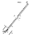
- This optimal spreading of the material G is also brought about by a driver, the mode of operation of which is explained with reference to FIG. 3.
- Fig. 3 shows that the bottom B of the goods tray W is provided with a sawtooth-shaped profile in cross section, which forms a path Ba running in the form of a spiral.
- This spiral path Ba forms an optimally acting driver, which in turn forms a conveying device by the rotation of the goods carrying tray W, which transports the goods G from the lower area into the upper area of the goods carrying tray W. In the upper area, the material G then slides over the inclined flanks of the sawtooth-shaped profile, which results in very good mixing.
- an inclination angle .alpha. and a rotational speed can be set for each good G, at which the good G is spread almost completely over the entire bottom surface of the goods carrying tray W with very thorough mixing.
- a perforation P can be made in the bottom B of the goods carrying tray W, through which the electrolyte exchange is further improved.
- an additional anode ZA can then be arranged at a distance parallel to the bottom B, which, like the anode A likewise only indicated, consists of pure aluminum and is composed of several segments.
- the perforation P and the additional anode ZA further improve the passage of current and bring about an additional increase in the deposition rates.
- Multiple arrangements of goods trays W which can be rotated together are also conceivable, in which case the additional anode ZA then serves simultaneously as the main anode of the subsequent goods tray W.
- a anode Ac axis Ao1, Ao2 shut-off device As export lock Aw drive shaft B floor Ba spiral path Bb bath container Be actuator D lid Because axis of rotation Dp1, Dp2 pivot point There import gate Esp electrolyte mirror For downpipe G pourable goods Ge frame Lg bearing housing P perforation Sch slide U arrow Vz adjusting cylinder W goods carrier Wa peripheral wall ZA additional anode ⁇ angle of inclination
Landscapes
- Chemical & Material Sciences (AREA)
- Engineering & Computer Science (AREA)
- Chemical Kinetics & Catalysis (AREA)
- Electrochemistry (AREA)
- Materials Engineering (AREA)
- Metallurgy (AREA)
- Organic Chemistry (AREA)
- Electroplating Methods And Accessories (AREA)
- Prevention Of Electric Corrosion (AREA)
Abstract
Description
- Die Erfindung betrifft eine Einrichtung für die Massengalvanisierung von schüttfähigem Gut, insbesondere zum galvanischen Abscheiden von Aluminium aus aprotischen, sauerstoff- und wasserfreien, aluminiumorganischen Elektrolyten, mit
- einem Badbehälter zur Aufnahme eines Elektrolyten,
- einer in den Elektrolyten eintauchenden und um ihre geneigte Achse drehbaren Warentragschale,
- mindestens einer in den Elektrolyten eintauchenden und zumindest weitgehend parallel zum Boden der Warentragschale ausgerichteten scheibenförmigen Anode und mit
- mindestens einem Mitnehmer für die Ausbreitung des schüttfähigen Gutes auf dem Boden der Warentragschale. - Beim Massengalvanisieren von schüttfähigem Gut muß das Galvanisiergut während der galvanischen Bearbeitung so zusammengehalten werden, daß jedes Einzelteil elektrischen Kontakt hat. Andererseits soll das Galvanisiergut so weit wie möglich ausgebreitet werden, damit die Metallabscheidung auf einer möglichst großen Warenoberfläche erfolgen kann und eine möglichst gleichmäßige Stromdichte auf allen Teilen gewährleistet ist. Diese beiden Forderungen müssen vom Warengefäß erfüllt werden. Eine weitere wesentliche Voraussetzung für die Erzielung einwandfreier Metallüberzüge mit einer gleichmäßigen Schichtdicke ist die ausreichende Durchmischung des Galvanisiergutes während der galvanischen Bearbeitung. Diese Durchmischung des Galvanisiergutes wird meist durch Drehen des Warengefäßes um eine nicht senkrechte Achse herbeigeführt, wobei je nach Form und Wandreibung die einzelnen Teile mehr oder weniger weit nach oben gefördert werden und dann wieder nach unten abrollen oder abgleiten. Trotz dieser Warenbewegung sollten jedoch ein dauernder elektrischer Kontakt und eine schonende Behandlung des Galvanisiergutes gewährleistet sein. Als weitere Erfordernisse für qualitativ hochwertige Metallüberzüge sind schließlich noch ein ausreichender Elektrolytaustausch ein möglichst ungehinderter Stromdurchgang zwischen Anoden und Galvanisiergut und ein ausreichende Größe und Anodenoberfläche im Verhältnis zur Warenoberfläche zu nennen.
- Das einfachste Warengefäß ist die Galvanisierglocke, ein drehbarer Topf, der zugleich als Badbehälter dient. Eine Durchmischung des Galvanisiergutes wird dadurch erreicht, daß man die Glocke, gegen die Senkrechte geneigt, dreht. Da die Anode in die Glocke eingehängt wird ist die Anodenoberfläche selbst bei Benutzung von profilierten Spezialanoden im Verhältnis zur Warenoberfläche meist zu klein. Dies führt dann aber zu geringen Abscheideraten und somit zu einer Verlängerung der Galvanisierdauer und einer Erhöhung des Abriebs.
- Für die Massengalvanisierung werden häufig auch Galvanisiertrommeln eingesetzt, die im Gegensatz zur Glocke nur als Warengefäß dienen und in einem Badbehälter angeordnet werden. Eine Durchmischung des Galvanisiergutes wird durch Drehen der Galvanisiertrommeln um eine waagrechte Achse bewirkt. Da sich die Anoden außerhalb des Trommelkörpers befinden, können größere Anodenoberflächen realisiert werden. Andererseits muß für den Stromdurchgang zwischen Anoden und Galvanisiergut in den Mantel des Trommelkörpers eine Perforation eingebracht werden. Der für den Stromdurchgang verfügbare offene Querschnitt einer derartigen Perforation ist jedoch aus Festigkeits gründen und im Hinblick auf die Größe des Galvanisiergutes so gering bemessen, daß es zu einer erheblichen Beeinträchtigung des Stromdurchgangs kommt. Dies führt dann aber auch hier wieder zu geringen Abscheideraten und somit zu einer Verlängerung der Galvanisierdauer und einer Erhöhung des Abriebs.
- Aus der DE-C- 830 862 ist eine Einrichtung der eingangs genannten Art bekannt, bei welcher die Warentragschale in ihrem Innern mit Rippen versehen ist, welche eine gleichmäßige Verteilung des schüttfähigen Gutes auf dem Boden der Warentragschale begünstigen. Die Rippen nehmen das schüttfähige Gut bei einer Drehung der Warentragschale mit nach oben, d. h. der auf den Boden der Warentragschale bezogene Ausbreitungsgrad wird durch die Rippen erheblich gesteigert. Sowohl die Warentragschale als auch ein zur Aufnahme des fertig galvanisierten Gutes dienender Behälter sind um eine oberhalb des Badbehälters gelagerte gemeinsame Welle derart schwenkbar gelagert, daß beide Behälter in eine solche gegenseitige Lage gebracht werden können, daß das schüttfähige Gut aus der Warentragschale in den Aufnahmebehälter entleert und dieser aus dem Elektrolyten herausgeschwenkt werden kann, während gleichzeitig die Warentragschale in die Arbeitsstellung zurückgeführt wird.
- Aus aprotischen, sauerstoff- und wasserfreien, aluminiumorganischen Elektrolyten abgeschiedenes Aluminium zeichnet sich durch seine Duktilität, Porenarmut, Korrosionsfestigkeit und Eloxierfähigkeit aus. Da der Zutritt von Luft durch Reaktion mit Luftsauerstoff und Luftfeuchtigkeit eine erhebliche Verringerung der Leitfähigkeit und Lebensdauer dieser Elektrolyten bewirkt, muß das Galvanisieren in einer unter Luftabschluß arbeitenden Einrichtung vorgenommen werden. Damit auch beim Be- und Entladen dieser unter Luftabschluß arbeitenden Einrichtungen der Zutritt von Luft verhindert werden kann, sind außerdem Ein- und Ausfuhrschleusen erforderlich, die als Gasschleusen, als Flüssigkeitsschleusen oder als kombinierte Gas-Flüssigkeits-Schleusen ausgebildet sind. Bei der Massenaluminierung unter Verwendung aprotischer, sauerstoff- und wasserfreier, aluminiumorganischer Elektrolyte kommt also zu den bereits erwähnten Schwierigkeiten zusätzlich noch das Problem hinzu, den Zutritt von Luft zum Elektrolyten möglichst weitgehend zu verhindern.
- Aus der DE-PS 30 23 129 ist eine Einrichtung zum galvanischen Abscheiden von Aluminium aus sauerstoff- und wasserfreien, aluminiumorganischen Elektrolyten bekannt, bei welcher eine um ihre waagerechte Achse drehbare Galvanisiertrommel in einem gasdicht verschließbaren Badbehälter angeordnet ist. Die mit einer Perforation versehene Galvanisiertrommel ist von zwei Anoden umgeben, die so verstellt werden können, daß sie eine Öffnung für das zu entleerende Schüttgut bilden. Das Beladen der Galvanisiertrommel erfolgt duch eine in das Innere des Badbehälters über eine Schleuse führende Transporteinrichtung, die über einer verschließbaren Öffnung der Galvanisiertrommel endet, wobei das Öffnen und Schließen der Galvanisiertrommel von außen vorgenommen wird. Zum Entleeren der Galvanisiertrommel dient ein als Ausfuhrschleuse ausgebildeter Ablaßbehälter, der unterhalb des Badbehälters angeordnet ist und mit diesem über ein absperrbares, rohrförmiges Verbindungsstück in Verbindung steht.
- Bei der bekannten Einrichtung zum galvanischen Abscheiden von Aluminium wurde das Problem den Zutritt von Luft zum Elektrolyten zu verhindern zufriedenstellend gelöst. Wie bei anderen Einrichtungen zum Trommelgalvanisieren kommt es jedoch auch hier zu einer Beeinträchtigung des Stromdurchgangs zwischen den außerhalb des Trommelkör pers angeordneten Anoden und dem sich im Inneren der Trommel befindlichen Galvanisiergut.
- Der Erfindung liegt die Aufgabe zugrunde, bei einer Einrichtung der eingangs genannten Art den auf den Boden der Warentragschale bezogenen Ausbreitungsgrad des schüttfähigen Gutes noch weiter zu verbessern. Die Einrichtung sollte überdies so konzipiert sein, daß sie mit einem vertretbaren, zusätzlichen Aufwand unter Luftabschluß betrieben und zur Massenaluminierung unter Verwendung aprotischer, sauerstoff- und wasserfreier, aluminiumorganischer Elektrolyte eingesetzt werden kann.
- Diese Aufgabe wird erfindungsgemäß dadurch gelöst, daß der Mitnehmer durch eine spiralförmig verlaufende Bahn gebildet ist. Eine derartige spiralförmige Bahn wirkt als Transporteinrichtung, welche das schüttfähige Gut aus den tieferen Bereichen der Warentragschale ständig in die oberen Bereiche fördert. Hierdurch kann eine vollständig gleichmäßige Bedeckung des Bodens der Warentragschale mit schüttfähigem Gut erreicht werden, wobei die spiralförmige Bahn auch gleichzeitig die Durchmischung des Gutes in starkem Maße fördert. Die Bahn kann auf besonders einfache Weise durch ein in den Boden der Warentragschale eingebrachtes Profil gebildet werden. Mit einem im Querschnitt sägezahnförmigen Profil kann dann insbesondere die Mitnahme des Gutes in die höhergelegenen Bereiche der Warentragschale noch weiter verbessert werden.
- Zur Verbesserung des Elektrolytaustausches kann der Boden der Warentragschale aber auch mit einer Perforation versehen werden. In diesem Fall kann außerdem unterhalb des Bodens eine mit Abstand parallel zum Boden ausgerichtete Zusatz-Anode angeordnet werden. Hierdurch wird die Anodenoberfläche noch weiter vergrößert, so daß besonders hohe Abscheideraten erzielt werden können.
- Gemäß einer weiteren bevorzugten Ausgestaltung der Erfindung ist in der peripheren Wand der Warentragschale ein Schieber für den Austrag des Gutes angeordnet. Wird dieser Schieber in der tiefstgelegenen Stellung seiner Umlaufbahn geöffnet, so ergibt sich eine selbsttätige Entleerung der Warentragschale.
- Für eine gute Durchmischung des Gutes hat es sich als besonders günstig herausgestellt, wenn der Neigungswinkel der Achse der Warentragschale zur Waagerechten etwa 30 bis 38° beträgt.
- Ist der Neigungswinkel der Achse der Warentragschale zur Waagerechten einstellbar, so wird im Hinblick auf die Ausbreitung und Durchmischung eine besonders gute Anpassung an die Erfordernisse des jeweiligen Galvanisiergutes ermöglicht. Vorzugsweise ist der Neigungswinkel der Achse dann über die Schrägstellung des gesamten Badbehälters einstellbar. Hierdurch wird dem Umstand Rechnung getragen, daß bei einer Verstellung der Achse die parallele Ausrichtung der Anode zum Boden der Waentragschale aufrechterhalten werden soll. Über die Schrägstellung des gesamten Badbehälters kann dann auf besonders einfache Weise eine synchrone Verstellung von Warentragschale und Anode gewährleistet werden. Zur einfachen Veränderung seiner Schrägstellung ist der Badbehälter zweckmäßigerweise schwenkbar auf einem Gestell angeordnet.
- Die erfindungsgemäße Einrichtung kann mit relativ geringem zusätzlichen Aufwand für die Massenaluminierung unter Verwendung aprotischer, sauerstoff- und wasserfreier, aluminiumorganischer Elektrolyte eingesetzt werden. Dies wird dadurch erreicht, daß der Badbehälter gasdicht verschließbar ist und daß für das Einbringen und Austragen des Gutes Schleusen vorgesehen sind. Der Badbehälter ist dann vorzugsweise mit einem im Bereich der Anode angeordneten Deckel versehen, so daß die Anode bei geöffneten Deckel leicht zugänglich ist und ggf. problemlos ausgetauscht werden kann.
- Ein Ausführungsbeispiel der Erfindung ist in der Zeichnung dargestellt und wird im folgenden näher beschrieben.
- Es zeigen in stark vereinfachter schematischer Darstellung:
- Fig. 1 eine Draufsicht auf eine Einrichtung für die Massenaluminierung von schüttfähigem Gut, wobei die Warentragschale durch einen entsprechenden Querschnitt des Badbehälters sichtbar ist,
- Fig. 2 einen Längsschnitt durch die in Fig. 1 dargestellte Einrichtung und
- Fig. 3 eine detaillierte Darstellung des Bodens der Warentragschale, in welchen durch ein im Querschnitt sägezahnförmiges Profil eine spiralförmig verlaufende Bahn als Mitnehmer gebildet ist.
- Die Fig. 1 und 2 zeigen eine Einrichtung für die Massenaluminierung von schüttfähigem Gut G in der teilweise aufgebrochenen Draufsicht bzw. im Längsschnitt. In einem auf einem Gestell Ge schräg angeordneten und mit Hilfe eines Deckels D gasdicht verschlossenen Badbehälter Bb befindet sich ein aprotischer, sauerstoff- und wasserfreier, aluminiumorganischer Elektrolyt, wobei der oberhalb des Elektrolytspiegels Esp liegende Bereich mit einem Inertgas, wie z. B. Stickstoff, beaufschlagt ist.
- Das zu aluminierende schüttfähige Gut G, bei welchem es sich beispielsweise um Schrauben, Muttern, Bolzen, Abstandsbuchsen und dergl. handelt, wird über eine in Fig. 2 nur angedeutete Einfuhrschleuse Es und ein sich daran anschließendes schräges Fallrohr Fr in den Badbehälter Bb eingebracht und fällt dann auf den Boden B einer insgesamt mit W bezeichneten und in den Elektrolyten vollständig eintauchenden Warentragschale. Die Warentragschale W besitzt die Form eines äußerst flachen Kreiszylinders, dessen periphere Wand mit Wa bezeichnet ist.
- Bei der Beladung der Warentragschale W mit dem zu galvanisierenden Gut und beim Galvanisierbetrieb wird die Warentragschale W in Richtung des Pfeiles U um ihre zur Waagerechten geneigte Achse Ac gedreht. Die entsprechende Antriebswelle Aw der Warentragschale Wl ist mit dem Boden B fest verbunden, durch die Wandung des Badbehälters Bb gas- und flüssigkeitsdicht hindurchgeführt und in einem von außen an der Wandung des Badbehälters Bb angebrachtes Lagergehäuse Lg gelagert. Der der Antriebswelle Aw zugeordnete Antrieb ist in der Zeichnung nicht dargestellt.
- Eine in geringem Abstand parallel zum Boden B und damit auch zum ausgebreiteten Gut G angeordnete scheibenförmige Anode A ist in Fig. 2 lediglich rein schematisch angedeutet. Die isolierte Befestigung dieser aus Reinaluminium bestehenden und aus mehreren Segmenten zusammengesetzten Anode A im Badbehälter Bb geht aus Fig. 2 nicht hervor. Es ist jedoch erkennbar, daß die Anode A bei geöffnetem Deckel D leicht ausgewechselt werden kann.
- Während der galvanischen Aluminiumabscheidung wird die Warentragschale W in Richtung des Pfeils U um ihre geneigte Achse Ac gedreht, wobei das Gut G gleichzeitig durchmischt wird. Aufgrund des unbehinderten Durchgangs des Galvanisierstroms zwischen der Anode A und der Warenoberfläche können hohe Abscheideraten erzielt werden, so daß das Gut G bereits nach einer relativ kurzen Verweilzeit wieder ausgetragen werden kann. Hierzu wird über ein im unteren Bereich der Warentragschale W am Badbehälter Bb befestigtes pneumatisches oder hydraulisches Betätigungselement Be ein in der peripheren Wand Wa angeordneter Schieber Sch hochgezogen. Auf diese Weise wird die Warentragschale auf einfache Weise rasch entleert. Das Gut G gelangt dann in den unteren trichterförmig ausgebildeten Bereich des Badbehälters Bb, an welchen sich ein erstes Absperrorgan Ao1, ein als Ausfuhrschleuse As wirkender Ablaßbehälter und ein zweites Absperrorgan Ao2 anschließen. Das Ausbringen des Gutes G umfaßt dann folgende Schritte:
- a) Öffnen des Absperrorgans Ao1, so daß das Gut G und ein Teil des Elektrolyten in die Ausfuhrschleuse As eintreten.
- b) Schließen des Absperrorgans Ao1.
- c) Elektrolyten aus Ausfuhrschleuse As in den Badbehälter Bb zurückpumpen.
- d) Ausfuhrschleuse As zum Spülen des Gutes G aus einem Vorratsbehälter mit Toluol füllen.
- e) Toluol in Vorratsbehälter zurückpumpen.
- f) Absperrorgan Ao2 zum Entleeren der Austragsschleuse As öffnen.
- Der Badbehälter Bb ist auf einem Gestell Ge schräg angeordnet, wobei die Schrägstellung durch Verschwenken des gesamten Badbehälters Bb verändert werden kann. Hierzu ist der Badbehälter Bb in seinem unteren Bereich über eine Drehachse Da an das Gestell Ge angelenkt, während ein pneumatisch oder hydraulisch betätigbarer Verstellzylinder Vz über einen ersten Drehpunkt Dp1 an den oberen Bereich des Badbehälters Bb und über einen zweiten Drehpunkt Dp2 an das Gestell Ge angelenkt ist. Auf diese Weise kann über den Verstellzylinder Vz die Schräg stellung des Bedbehälters Bb und damit auch der Neigungswinkel α der Achse Ac der Warentragschale W1 zur Waagerechten eingestellt werden. Ggf. wird auch beim Entleeren der Warentragschale W der Neigungswinkel α verringert.
- Für die in den Fig. 1 und 2 schematisch dargestellte Einrichtung können folgende Abmessungen und Betriebswerke genannt werden:
- Durchmesser der Warentragschale W1: 3,0 m
Schüttgewicht des Gutes G: ca. 300 kg
Anodische Stromdichte: 1,0 A/dm²
Kathodische Stomdichte: 0,5 - 1,0 A/dm²
Neigungswinkel α : 30 - 38°
Drehzahl der Warentragschale W1: 2 - 12 U/min - Die Drehzahl und der Neigungswinkel α können dabei so auf das jeweils zu aluminierende Gut G abgestimmt werden, daß sich die in Fig. 1 dargestellte vollständig gleichmäßige Ausbreitung des Gutes G ergibt. Diese optimale Ausbreitung des Gutes G wird auch durch einen Mitnehmer bewirkt, dessen Wirkungsweise anhand der Fig. 3 erläutert wird.
- Fig. 3 zeigt, daß der Boden B der Warentragschale W mit einem im Querschnitt sägezahnförmigen Profil versehen ist, welches eine in Form einer Spirale verlaufende Bahn Ba bildet. Diese spiralförmige Bahn Ba bildet einen optimal wirkenden Mitnehmer, der durch die Drehung der Warentragschale W seinerseits eine Fördereinrichtung bildet, die das Gut G aus dem unteren Bereich in den oberen Bereich der Warentragschale W transportiert. Im oberen Bereich rutscht das Gut G dann über die geneigten Flanken des sägezahnförmigen Profils ab, wordurch sich eine sehr gute Durchmischung ergibt. Anhand von Versuchen konnte festgestellt werden, daß für jedes Gut G ein Neigungswinkel α und eine Drehzahl eingestellt werden können, bei welchen das Gut G bei sehr starker Durchmischung nahezu vollständig über die gesamte Bodenfläche der Warentragschale W ausgebreitet wird.
- Im unteren Bereich der Fig. 3 ist angedeutet, daß in dem Boden B der Warentragschale W eine Perforation P eingebracht werden kann, durch welche der Elektrolytaustausch weiter verbessert wird. Ferner ist angedeutet, daß dann im Abstand parallel zum Boden B eine Zusatz-Anode ZA angeordnet werden kann, die wie die ebenfalls nur angedeutete Anode A aus Reinaluminium besteht und aus mehreren Segmenten zusammengesetzt ist. Durch die Perforation P und die Zusatz-Anode ZA wird der Stromdurchgang weiter verbessert und eine zusätzliche Steigerung der Abscheideraten bewirkt. Es sind auch Mehrfachanordnungen gemeinsam drehbarer Warentragschalen W denkbar, wobei hier dann die Zusatz-Anode ZA gleichzeitig als Hauptanode der nachfolgenden Warentragschale W dient.
- A Anode
Ac Achse
Ao1, Ao2 Absperrorgan
As Ausfuhrschleuse
Aw Antriebswelle
B Boden
Ba spiralförmige Bahn Bb Badbehälter Be Betätigungselement D Deckel
Da Drehachse
Dp1, Dp2 Drehpunkt
Es Einfuhrschleuse
Esp Elektrolytspiegel
Fr Fallrohr
G schüttfähiges Gut
Ge Gestell
Lg Lagergehäuse
P Perforation
Sch Schieber
U Pfeil
Vz Verstellzylinder
W Warentragschale
Wa periphere Wand
ZA Zusatz-Anode
α Neigungswinkel
Claims (12)
- einem Badbehälter zur Aufnahme eines Elektrolyten,
- einer in den Elektrolyten eintauchenden und um ihre geneigte Achse drehbaren Warentragschale,
- mindestens einer in den Elektrolyten eintauchenden und zumindest weitgehend parallel zum Boden der Warentragschale ausgerichteten scheibenförmigen Anode und mit
- mindestens einem Mitnehmer für die Ausbreitung des schüttfähigen Gutes auf dem Boden der Warentragschale, dadurch gekennzeichnet, daß der Mitnehmer durch eine spiralförmig verlaufende Bahn (Ba) gebildet ist.
Priority Applications (1)
| Application Number | Priority Date | Filing Date | Title |
|---|---|---|---|
| AT86111907T ATE90742T1 (de) | 1985-09-17 | 1986-08-28 | Einrichtung fuer die massengalvanisierung von schuettfaehigem gut. |
Applications Claiming Priority (4)
| Application Number | Priority Date | Filing Date | Title |
|---|---|---|---|
| DE3533151 | 1985-09-17 | ||
| DE3533151 | 1985-09-17 | ||
| DE3616429 | 1986-05-15 | ||
| DE3616429 | 1986-05-15 |
Publications (2)
| Publication Number | Publication Date |
|---|---|
| EP0222087A1 true EP0222087A1 (de) | 1987-05-20 |
| EP0222087B1 EP0222087B1 (de) | 1993-06-16 |
Family
ID=25836065
Family Applications (1)
| Application Number | Title | Priority Date | Filing Date |
|---|---|---|---|
| EP86111907A Expired - Lifetime EP0222087B1 (de) | 1985-09-17 | 1986-08-28 | Einrichtung für die Massengalvanisierung von schüttfähigem Gut |
Country Status (4)
| Country | Link |
|---|---|
| US (1) | US4696728A (de) |
| EP (1) | EP0222087B1 (de) |
| CA (1) | CA1315238C (de) |
| DE (1) | DE3688583D1 (de) |
Families Citing this family (5)
| Publication number | Priority date | Publication date | Assignee | Title |
|---|---|---|---|---|
| US4946572A (en) * | 1989-12-27 | 1990-08-07 | Ford Motor Company | Electroplating of precision parts |
| US4992145A (en) * | 1989-12-27 | 1991-02-12 | Ford Motor Company | Electroplating of precision parts |
| US6228230B1 (en) | 1999-04-19 | 2001-05-08 | Aem, Inc. | Electroplating apparatus |
| CN103484926A (zh) * | 2013-09-09 | 2014-01-01 | 浙江英洛华磁业有限公司 | 滚筒活动门 |
| CN110340467B (zh) * | 2019-06-28 | 2020-07-28 | 南京航空航天大学 | 开口对称式阴极榫槽电解加工装置及方法 |
Citations (2)
| Publication number | Priority date | Publication date | Assignee | Title |
|---|---|---|---|---|
| DE830862C (de) * | 1950-10-20 | 1952-02-07 | Friedr Blasberg Fa | Apparat zur Massenverchromung |
| DE1496999A1 (de) * | 1964-09-04 | 1969-05-29 | Sel Rex Corp | Vorrichtung zur elektrochemischen Behandlung von Massenartikeln |
Family Cites Families (1)
| Publication number | Priority date | Publication date | Assignee | Title |
|---|---|---|---|---|
| DE3023129C2 (de) * | 1980-06-20 | 1982-04-15 | Siemens AG, 1000 Berlin und 8000 München | Vorrichtung zum galvanischen Abscheiden von Aluminium |
-
1986
- 1986-08-28 DE DE8686111907T patent/DE3688583D1/de not_active Expired - Fee Related
- 1986-08-28 EP EP86111907A patent/EP0222087B1/de not_active Expired - Lifetime
- 1986-09-11 US US06/906,037 patent/US4696728A/en not_active Expired - Fee Related
- 1986-09-15 CA CA000518158A patent/CA1315238C/en not_active Expired - Fee Related
Patent Citations (2)
| Publication number | Priority date | Publication date | Assignee | Title |
|---|---|---|---|---|
| DE830862C (de) * | 1950-10-20 | 1952-02-07 | Friedr Blasberg Fa | Apparat zur Massenverchromung |
| DE1496999A1 (de) * | 1964-09-04 | 1969-05-29 | Sel Rex Corp | Vorrichtung zur elektrochemischen Behandlung von Massenartikeln |
Also Published As
| Publication number | Publication date |
|---|---|
| CA1315238C (en) | 1993-03-30 |
| DE3688583D1 (de) | 1993-07-22 |
| US4696728A (en) | 1987-09-29 |
| EP0222087B1 (de) | 1993-06-16 |
Similar Documents
| Publication | Publication Date | Title |
|---|---|---|
| DE2537256C3 (de) | Vorrichtung zum galvanischen Abscheiden von Aluminium | |
| EP0222087B1 (de) | Einrichtung für die Massengalvanisierung von schüttfähigem Gut | |
| EP0042503B1 (de) | Vorrichtung zum galvanischen Abscheiden von Aluminium | |
| EP0220419B1 (de) | Einrichtung für die Massengalvanisierung von schüttfähigem Gut | |
| EP0070011A1 (de) | Galvanisiereinrichtung | |
| DE4217615A1 (de) | Verfahren zum beschichten von werkstuecken mit farbe durch elektrolytische abscheidung | |
| DE2902352C3 (de) | Verfahren und Vorrichtung zum Tauchbeschichten von Werkstücken, insbesondere von Containern | |
| CH633049A5 (de) | Vorrichtung zum galvanisieren von werkstuecken mit aluminium. | |
| EP0209016B1 (de) | Einrichtung zur elektrolytischen Oberflächenbehandlung von schüttfähigem Gut | |
| DE3103593A1 (de) | Dragiertrommel zum ueberziehen von tabletten u.dgl. | |
| DE3133162C2 (de) | Vorrichtung zum galvanischen Abscheiden von Aluminium | |
| DE2422870A1 (de) | Spannvorrichtung | |
| EP0209766B1 (de) | Einrichtung zur elektrolytischen Oberflächenbehandlung von schüttfähigem Gut | |
| EP0053676B1 (de) | Vorrichtung zum galvanischen Abscheiden von Aluminium | |
| DE10344475B3 (de) | Vorrichtung zur Oberflächenbeschichtung von Kleinteilen | |
| DE19613927C1 (de) | Verfahren und Vorrichtung zum Beschichten von Kleinteilen | |
| EP0042504B1 (de) | Vorrichtung und Verfahren zum galvanischen Abscheiden von Aluminium | |
| DE4037336A1 (de) | Galvanisiertrommel | |
| EP0209015B1 (de) | Einrichtung zur Oberflächenbehandlung von schüttfähigem Gut | |
| DE3519906C1 (de) | Verfahren und Vorrichtung zur galvanischen Beschichtung eines Hohlkörpers mit verschieden gerichteten Ausnehmungen oder Hinterschneidungen und die Anwendung des Verfahrens | |
| EP0433490A1 (de) | Einrichtung zur Oberflächenbehandlung von schüttfähigem Gut | |
| DE2610625A1 (de) | Vorrichtung zur behandlung von werkstuecken in baedern | |
| DE3019719A1 (de) | Vorrichtung zum chargenweisen oberflaechenbehandlung von werkstuecken, insbesondere zum galvanisieren | |
| CH510746A (de) | Vorrichtung zum galvanischen Veredeln von Formteilen | |
| EP0209004A1 (de) | Läppeinrichtung zur Oberflächenverbesserung von schüttfähigem Gut |
Legal Events
| Date | Code | Title | Description |
|---|---|---|---|
| PUAI | Public reference made under article 153(3) epc to a published international application that has entered the european phase |
Free format text: ORIGINAL CODE: 0009012 |
|
| AK | Designated contracting states |
Kind code of ref document: A1 Designated state(s): AT BE CH DE FR GB IT LI NL SE |
|
| 17P | Request for examination filed |
Effective date: 19870604 |
|
| 17Q | First examination report despatched |
Effective date: 19880728 |
|
| GRAA | (expected) grant |
Free format text: ORIGINAL CODE: 0009210 |
|
| AK | Designated contracting states |
Kind code of ref document: B1 Designated state(s): AT BE CH DE FR GB IT LI NL SE |
|
| REF | Corresponds to: |
Ref document number: 90742 Country of ref document: AT Date of ref document: 19930715 Kind code of ref document: T |
|
| PGFP | Annual fee paid to national office [announced via postgrant information from national office to epo] |
Ref country code: GB Payment date: 19930714 Year of fee payment: 8 |
|
| PGFP | Annual fee paid to national office [announced via postgrant information from national office to epo] |
Ref country code: AT Payment date: 19930716 Year of fee payment: 8 |
|
| REF | Corresponds to: |
Ref document number: 3688583 Country of ref document: DE Date of ref document: 19930722 |
|
| ET | Fr: translation filed | ||
| PGFP | Annual fee paid to national office [announced via postgrant information from national office to epo] |
Ref country code: SE Payment date: 19930813 Year of fee payment: 8 |
|
| PGFP | Annual fee paid to national office [announced via postgrant information from national office to epo] |
Ref country code: BE Payment date: 19930818 Year of fee payment: 8 |
|
| PGFP | Annual fee paid to national office [announced via postgrant information from national office to epo] |
Ref country code: FR Payment date: 19930819 Year of fee payment: 8 |
|
| PGFP | Annual fee paid to national office [announced via postgrant information from national office to epo] |
Ref country code: NL Payment date: 19930831 Year of fee payment: 8 |
|
| ITF | It: translation for a ep patent filed | ||
| GBT | Gb: translation of ep patent filed (gb section 77(6)(a)/1977) |
Effective date: 19930823 |
|
| PGFP | Annual fee paid to national office [announced via postgrant information from national office to epo] |
Ref country code: DE Payment date: 19931020 Year of fee payment: 8 |
|
| PGFP | Annual fee paid to national office [announced via postgrant information from national office to epo] |
Ref country code: CH Payment date: 19931116 Year of fee payment: 8 |
|
| PLBE | No opposition filed within time limit |
Free format text: ORIGINAL CODE: 0009261 |
|
| STAA | Information on the status of an ep patent application or granted ep patent |
Free format text: STATUS: NO OPPOSITION FILED WITHIN TIME LIMIT |
|
| 26N | No opposition filed | ||
| PG25 | Lapsed in a contracting state [announced via postgrant information from national office to epo] |
Ref country code: GB Effective date: 19940828 Ref country code: AT Effective date: 19940828 |
|
| PG25 | Lapsed in a contracting state [announced via postgrant information from national office to epo] |
Ref country code: SE Effective date: 19940829 |
|
| PG25 | Lapsed in a contracting state [announced via postgrant information from national office to epo] |
Ref country code: LI Effective date: 19940831 Ref country code: CH Effective date: 19940831 Ref country code: BE Effective date: 19940831 |
|
| EAL | Se: european patent in force in sweden |
Ref document number: 86111907.1 |
|
| BERE | Be: lapsed |
Owner name: SIEMENS A.G. Effective date: 19940831 |
|
| PG25 | Lapsed in a contracting state [announced via postgrant information from national office to epo] |
Ref country code: NL Effective date: 19950301 |
|
| NLV4 | Nl: lapsed or anulled due to non-payment of the annual fee | ||
| GBPC | Gb: european patent ceased through non-payment of renewal fee |
Effective date: 19940828 |
|
| PG25 | Lapsed in a contracting state [announced via postgrant information from national office to epo] |
Ref country code: FR Effective date: 19950428 |
|
| REG | Reference to a national code |
Ref country code: CH Ref legal event code: PL |
|
| PG25 | Lapsed in a contracting state [announced via postgrant information from national office to epo] |
Ref country code: DE Effective date: 19950503 |
|
| EUG | Se: european patent has lapsed |
Ref document number: 86111907.1 |
|
| REG | Reference to a national code |
Ref country code: FR Ref legal event code: ST |
|
| PG25 | Lapsed in a contracting state [announced via postgrant information from national office to epo] |
Ref country code: IT Free format text: LAPSE BECAUSE OF NON-PAYMENT OF DUE FEES;WARNING: LAPSES OF ITALIAN PATENTS WITH EFFECTIVE DATE BEFORE 2007 MAY HAVE OCCURRED AT ANY TIME BEFORE 2007. THE CORRECT EFFECTIVE DATE MAY BE DIFFERENT FROM THE ONE RECORDED. Effective date: 20050828 |
|
| APAH | Appeal reference modified |
Free format text: ORIGINAL CODE: EPIDOSCREFNO |