EP0222096A1 - Dispositif de transport de feuilles de verre mises sur chant - Google Patents
Dispositif de transport de feuilles de verre mises sur chant Download PDFInfo
- Publication number
- EP0222096A1 EP0222096A1 EP86112376A EP86112376A EP0222096A1 EP 0222096 A1 EP0222096 A1 EP 0222096A1 EP 86112376 A EP86112376 A EP 86112376A EP 86112376 A EP86112376 A EP 86112376A EP 0222096 A1 EP0222096 A1 EP 0222096A1
- Authority
- EP
- European Patent Office
- Prior art keywords
- support wall
- conveyor
- wall
- glass panes
- support
- Prior art date
- Legal status (The legal status is an assumption and is not a legal conclusion. Google has not performed a legal analysis and makes no representation as to the accuracy of the status listed.)
- Granted
Links
- 239000011521 glass Substances 0.000 title claims abstract description 40
- 238000004519 manufacturing process Methods 0.000 description 3
- 125000006850 spacer group Chemical group 0.000 description 2
- 238000009825 accumulation Methods 0.000 description 1
- 230000003749 cleanliness Effects 0.000 description 1
- 230000001419 dependent effect Effects 0.000 description 1
- 238000011161 development Methods 0.000 description 1
- 230000018109 developmental process Effects 0.000 description 1
- 230000000694 effects Effects 0.000 description 1
- 239000005357 flat glass Substances 0.000 description 1
- 239000003292 glue Substances 0.000 description 1
- 239000000565 sealant Substances 0.000 description 1
- 238000007789 sealing Methods 0.000 description 1
- 238000005406 washing Methods 0.000 description 1
Images

Classifications
-
- B—PERFORMING OPERATIONS; TRANSPORTING
- B65—CONVEYING; PACKING; STORING; HANDLING THIN OR FILAMENTARY MATERIAL
- B65G—TRANSPORT OR STORAGE DEVICES, e.g. CONVEYORS FOR LOADING OR TIPPING, SHOP CONVEYOR SYSTEMS OR PNEUMATIC TUBE CONVEYORS
- B65G49/00—Conveying systems characterised by their application for specified purposes not otherwise provided for
- B65G49/05—Conveying systems characterised by their application for specified purposes not otherwise provided for for fragile or damageable materials or articles
- B65G49/06—Conveying systems characterised by their application for specified purposes not otherwise provided for for fragile or damageable materials or articles for fragile sheets, e.g. glass
- B65G49/063—Transporting devices for sheet glass
Definitions
- Device for conveying upright glass panes in the horizontal direction with the features according to the preamble of claim 1 are prior art (DE 33 08 079 C2). They are used, for example, in production lines for double or multi-pane insulating glass. Such production lines usually consist of a glass washing machine, followed by a test station in which the cleanliness of the glass panes is checked, followed by a frame laying station in which spacer frames are applied to individual glass panes, followed by an assembly station in which the glass panes are put together with a spacer inserted and glued, possibly followed by a press in which panes of this type are pressed, and possibly followed by a sealing station in which a joint formed at the edge of the insulating glass pane is sealed by means of a viscous-pasty sealant, and finally followed by a removal station, in which the finished insulating glass panes are removed from the production line.
- All of these stations are passed through by the glass panes, i.e. they stand upright on a stand-up conveyor (usually a horizontal sequence of driven rollers, the axes of which run horizontally or almost horizontally; or a supported, horizontally running, endless conveyor belt; or a horizontally running conveyor chain with Supports for setting up the glass panes; or a pair of conveyor chains, which grips the individual glass panes or insulating glass panes on the lower edge on both sides and clamps them in and, if necessary, supports them on the lower edges by means of appropriate supports; the horizontal or approximately horizontal plane on which the individual or insulating glass panes stand with their lower edge is referred to here as the transport plane) and lean weakly (usually 5 ° to 7 °) against the vertical against a support device so that they do not fall over.
- a stand-up conveyor usually a horizontal sequence of driven rollers, the axes of which run horizontally or almost horizontally; or a supported, horizontally running, endless conveyor belt; or a
- the air cushion walls usually consist of a coated wooden plate, which is drilled at regular intervals perpendicular to its front to form air outlet openings distributed over its front.
- the back of the wooden plate is covered in the known air cushion walls by a box, which is supplemented by the wooden plate to a closed housing, in which a blower blows air through a supply line, which exits through the holes in the wooden plate and thereby leans against the wooden plate Glass pane lifts slightly from it and an air cushion is built up between the glass pane and wooden plate, via which the glass pane * can be supported on the wooden plate without contact.
- an air cushion wall which has no air outlet openings in its front, but instead a slot nozzle is provided longitudinally below its lower edge with upward outlet openings from which the blower air into the space between the support wall and the glass pane leaning against it can flow in.
- Devices for conveying glass panes are required to be suitable for all pane formats that occur in practice.
- the range of disc formats that can be found in practice is quite large, ranging from edge lengths of around 20cm to edge lengths of around 3m.
- problems have to be conveyed equally well and reliably with large and heavy as well as small and light glass panes. If the air cushion walls are optimized for the conveyance of heavy disks in the known devices, then there is the risk that light disks are blown too strongly and from the support wall dump. If, on the other hand, the air cushion wall is optimized for the conveyance of light disks in known devices, there is a risk that heavy disks cannot be lifted off the support wall, but rather grind against them.
- the invention has for its object to improve a device of the type mentioned in such a way that small and light as well as large and heavy glass panes can be easily and reliably conveyed floating on an air cushion with unchanged blower output.
- outlet openings in the form of obliquely upwardly directed slits which are provided along the lower edge of the support wall, can solve the task, in particular if they are supplemented by further conventional air outlet openings in the support wall, provided that these are not too close to the slots according to the invention, but are only distributed in the supporting wall from a distance of at least 80 cm, preferably from a distance of 100 to 120 cm from the transport plane.
- the air flow emerging from the slots between the supporting wall and the respective glass pane creates a vacuum which is sufficiently large to ensure that the glass panes tilt away from the supporting wall to prevent.
- the air cushion is stabilized by the novel arrangement of the air outlet slots, i.e. it is not so easy even under the pressure of heavy glass panes breaks down as in the known devices.
- the load-bearing capacity of the air cushion for heavy glass panes can advantageously be improved by additional air outlet openings in the upper region of the support wall, these being arranged so high that they blow on the large and heavy panes, but not the small and light panes, in which case they tend to be Risk of tipping over.
- the slots in the support wall can fully fulfill their purpose, they should extend essentially over the full length of the support wall.
- the effect sought according to the invention can be achieved with a single slot, but for constructional reasons it is simpler to arrange a plurality of slots one behind the other in the supporting wall.
- the distance between the slots and the lower edge of the support wall depends primarily on which disk formats the device should be able to convey. If - as is the practice - formats from an edge length of 20 cm should be able to be conveyed, the slots must of course be correspondingly closely above the lower edge of the supporting wall, preferably at a distance between 5 and 10 cm from the lower edge of the supporting wall.
- the support wall so that its lower edge is approximately 10 cm above the transport plane, then with slices that are 5 to 10 cm above the lower edge of the support wall, for panes with an edge length From 20cm a perfect transport is already possible.
- support rollers are provided between the support wall and the stand-up conveyor with an axis of rotation running at right angles to the conveying direction parallel to the support wall, the running surface of which protrudes slightly in front of the front of the support wall. It is thereby achieved that between the glass panes and the support wall there is a small air gap widening from bottom to top, into which the air flow which emerges from the slots in the support wall can easily spread out.
- these support rollers prevent small disks from being pressed too hard against the support wall by the negative pressure prevailing in the air flow, as a result of which their running could be inhibited.
- the additional air outlet openings preferably provided in the upper region of the support wall can extend at right angles to the front of the support wall Holes through which the large glass panes are blown.
- the lower ones are directed obliquely downwards and the upper ones obliquely upwards, so that the operating personnel can exit the air outlet openings that are temporarily not covered by glass panes Air is not blown directly into the face.
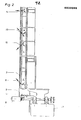
- a rectangular, flat supporting wall 2 rests on a base frame, which is held in a slightly inclined position (a few degrees deviation from the vertical). Beneath the support wall 2 rests on the underframe a support 7, which extends over the entire length of the device and is covered by a housing, and which supports a series of cylindrical, synchronously drivable rollers 8, the axes of rotation of which, at a corresponding level, run at right angles to the support wall 2.
- the rollers 8 form the stand-up conveyor, on which the glass panes 9, standing upright and leaning against the support wall 2, are transported in a horizontal direction (for example arrow 10) and define with their common upper tangential plane the transport plane of the stand-up conveyor. Not far above the lower edge of the support wall 2 there are several slots 11 in the front 3 of the support wall in the direction of transport 10, which run parallel to the lower edge of the support wall and are directed obliquely upwards.
- the distance of the lower edge of the support wall 2 from the upper side of the rollers 8 is preferably not more than 10 cm, and the slots 11 in the front 3 of the support wall are preferably not more than 7 cm above the lower edge of the support wall.
- the lines with the holes 12 and 13 are approximately at eye level of the operating personnel, from which it is expedient that the lower holes 12 run obliquely downwards and the upper holes 13 run obliquely upwards to be arranged so that the air from them does not enter the operator Face is blown.
- the slots 11 and the bores 12, 13 and 14 are connected to a cavity 4 in the support wall 2, into which air can be blown in by a blower, not shown, which flows through the slots 11 and the bores 12, 13 and 14 leaves again.
- a horizontal row of support rollers 5 is fixed to the frame.
- the support rollers 5 are freely rotatable and their axis of rotation runs parallel to the front side 3 of the support wall and at right angles to the transport direction 10.
- the arrangement of the support rollers 5 is such that it with its running surface, which is intended to rest on the glass panes 9 to be conveyed , a little - preferably 2 to 5 mm - in front of the plane in which the front 3 of the support wall 2 is located.
- the glass panes 9 from the outset keep a small distance from the front 3 of the support wall in their lower region, a gap widening from bottom to top forming between them, into which the air flowing out of the slots 11 easily flows and can build up an air cushion that completely lifts the glass panes 9 off the supporting wall 2.
- the support rollers 5 prevent the glass panes from being in the air flow between them and the support wall. Glue the vacuum too strongly to the retaining wall, which could possibly prevent it from running.
Landscapes
- Re-Forming, After-Treatment, Cutting And Transporting Of Glass Products (AREA)
- Chain Conveyers (AREA)
- Container, Conveyance, Adherence, Positioning, Of Wafer (AREA)
Priority Applications (1)
| Application Number | Priority Date | Filing Date | Title |
|---|---|---|---|
| AT86112376T ATE37521T1 (de) | 1985-10-16 | 1986-09-06 | Vorrichtung zum foerdern von hochkant stehenden glasscheiben. |
Applications Claiming Priority (2)
| Application Number | Priority Date | Filing Date | Title |
|---|---|---|---|
| DE19853536846 DE3536846A1 (de) | 1985-10-16 | 1985-10-16 | Vorrichtung zum foerdern von hochkant stehenden glasscheiben |
| DE3536846 | 1985-10-16 |
Publications (2)
| Publication Number | Publication Date |
|---|---|
| EP0222096A1 true EP0222096A1 (fr) | 1987-05-20 |
| EP0222096B1 EP0222096B1 (fr) | 1988-09-28 |
Family
ID=6283696
Family Applications (1)
| Application Number | Title | Priority Date | Filing Date |
|---|---|---|---|
| EP86112376A Expired EP0222096B1 (fr) | 1985-10-16 | 1986-09-06 | Dispositif de transport de feuilles de verre mises sur chant |
Country Status (5)
| Country | Link |
|---|---|
| US (1) | US5027941A (fr) |
| EP (1) | EP0222096B1 (fr) |
| AT (1) | ATE37521T1 (fr) |
| CA (1) | CA1269632A (fr) |
| DE (2) | DE3536846A1 (fr) |
Families Citing this family (13)
| Publication number | Priority date | Publication date | Assignee | Title |
|---|---|---|---|---|
| DE8905421U1 (de) * | 1989-04-28 | 1990-03-29 | Lenhardt Maschinenbau GmbH, 7531 Neuhausen | Vorrichtung zum Fördern von am Rand miteinander verklebten Isolierglasscheiben |
| DE4029669C1 (fr) * | 1990-09-19 | 1991-07-18 | Lenhardt Maschinenbau Gmbh, 7531 Neuhausen, De | |
| DE10319379A1 (de) * | 2003-04-30 | 2004-11-25 | Applied Films Gmbh & Co. Kg | Vorrichtung zum Transportieren eines flachen Substrats in einer Vakuumkammer |
| US20050093207A1 (en) * | 2003-10-30 | 2005-05-05 | Simone John D. | Injection molding lid transfer apparatus and method |
| KR101049926B1 (ko) * | 2004-02-18 | 2011-07-15 | 코닝 제팬 가부시끼 가이샤 | 판재의 종형 가공 라인 |
| CN101269749B (zh) * | 2008-04-10 | 2012-05-23 | 友达光电股份有限公司 | 传送导引机构 |
| US8047354B2 (en) * | 2008-09-26 | 2011-11-01 | Corning Incorporated | Liquid-ejecting bearings for transport of glass sheets |
| US8511461B2 (en) * | 2008-11-25 | 2013-08-20 | Corning Incorporated | Gas-ejecting bearings for transport of glass sheets |
| JP2013528544A (ja) * | 2010-05-03 | 2013-07-11 | イノバ・リゼツク・テクノロジーツエントルム・ゲゼルシヤフト・ミツト・ベシユレンクテル・ハフツング | 板状素子を運搬するための装置 |
| JP5912642B2 (ja) * | 2012-02-20 | 2016-04-27 | 日本電気硝子株式会社 | ガラス板の搬送装置及びその搬送方法 |
| KR102853365B1 (ko) * | 2019-12-18 | 2025-08-29 | 코닝 인코포레이티드 | 유리 운반 장치 및 이를 포함하는 복층 유리 유닛 제조 시스템 |
| KR102906035B1 (ko) | 2019-12-18 | 2025-12-29 | 코닝 인코포레이티드 | 복층 유리 유닛 및 그 제조 방법 |
| DE102023126130B3 (de) | 2023-09-26 | 2024-09-05 | Glaston Germany GmbH | Verfahren und Vorrichtung zum Zusammenbauen einer zwei Außengläser und ein dazwischen liegendes Dünnglas enthaltenden Dreifach-Isolierglasscheibe |
Citations (3)
| Publication number | Priority date | Publication date | Assignee | Title |
|---|---|---|---|---|
| DE3101342A1 (de) * | 1981-01-17 | 1982-07-29 | Vereinigte Glaswerke Gmbh, 5100 Aachen | "verfahren zur herstellung von gasgefuellten isolierglaseinheiten und vorrichtung zur durchfuehrung des verfahrens" |
| DE3232451C1 (de) * | 1982-09-01 | 1983-12-29 | Vereinigte Glaswerke Gmbh, 5100 Aachen | Luftkissen-Stützvorrichtung für Glasscheiben |
| DE3308079C2 (de) * | 1983-03-08 | 1985-01-17 | Karl 7531 Neuhausen Lenhardt | Vorrichtung zum Fördern von hochkant stehenden Glasscheiben |
Family Cites Families (6)
| Publication number | Priority date | Publication date | Assignee | Title |
|---|---|---|---|---|
| NL302621A (fr) * | 1962-12-28 | |||
| US3346360A (en) * | 1964-05-06 | 1967-10-10 | Libbey Owens Ford Glass Co | Apparatus for heat treating and conveying glass sheets vertically oriented |
| US3485616A (en) * | 1966-08-12 | 1969-12-23 | Permaglas Inc | Glass sheet conveying and treating apparatus |
| US3630706A (en) * | 1968-03-18 | 1971-12-28 | Libbey Owens Ford Co | Method and apparatus for bending and tempering glass sheets |
| US3734567A (en) * | 1971-01-25 | 1973-05-22 | Bangor Punta Operations Inc | Air conveyor for flat thin articles |
| US4010981A (en) * | 1973-09-20 | 1977-03-08 | Hodge Trevor A | Air conveyor with tunnel guide |
-
1985
- 1985-10-16 DE DE19853536846 patent/DE3536846A1/de not_active Withdrawn
-
1986
- 1986-09-06 AT AT86112376T patent/ATE37521T1/de not_active IP Right Cessation
- 1986-09-06 DE DE8686112376T patent/DE3660799D1/de not_active Expired
- 1986-09-06 EP EP86112376A patent/EP0222096B1/fr not_active Expired
- 1986-10-15 CA CA000520541A patent/CA1269632A/fr not_active Expired - Fee Related
-
1990
- 1990-05-01 US US07/517,425 patent/US5027941A/en not_active Expired - Fee Related
Patent Citations (3)
| Publication number | Priority date | Publication date | Assignee | Title |
|---|---|---|---|---|
| DE3101342A1 (de) * | 1981-01-17 | 1982-07-29 | Vereinigte Glaswerke Gmbh, 5100 Aachen | "verfahren zur herstellung von gasgefuellten isolierglaseinheiten und vorrichtung zur durchfuehrung des verfahrens" |
| DE3232451C1 (de) * | 1982-09-01 | 1983-12-29 | Vereinigte Glaswerke Gmbh, 5100 Aachen | Luftkissen-Stützvorrichtung für Glasscheiben |
| DE3308079C2 (de) * | 1983-03-08 | 1985-01-17 | Karl 7531 Neuhausen Lenhardt | Vorrichtung zum Fördern von hochkant stehenden Glasscheiben |
Also Published As
| Publication number | Publication date |
|---|---|
| US5027941A (en) | 1991-07-02 |
| CA1269632A (fr) | 1990-05-29 |
| EP0222096B1 (fr) | 1988-09-28 |
| ATE37521T1 (de) | 1988-10-15 |
| DE3660799D1 (en) | 1988-11-03 |
| DE3536846A1 (de) | 1987-04-16 |
Similar Documents
| Publication | Publication Date | Title |
|---|---|---|
| DE4029669C1 (fr) | ||
| EP0222096B1 (fr) | Dispositif de transport de feuilles de verre mises sur chant | |
| EP0603148B1 (fr) | Procédé et dispositif pour remplir des vitrages isolants avec un gaz différent de l'air | |
| DE29504900U1 (de) | Vorrichtung zum Zusammenbauen von Isolierglasscheiben, deren Innenraum mit einem Schwergas gefüllt ist | |
| DE3539879A1 (de) | Vorrichtung fuer das schlupffreie foerdern von zwei tafeln, insbesondere von glastafeln | |
| DE69508636T2 (de) | Vorrichtung zum Fordern und Schneiden von Flachmaterial auf einem Vakuumtisch mit einer Vorrichtung zum Dichten von den Endbereichen des Tisches | |
| EP1157184B2 (fr) | Dispositif permettant de transporter des vitres isolantes | |
| AT405618B (de) | Vorrichtung zum sortieren von glastafelzuschnitten | |
| DE19701426A1 (de) | Trockner für band- oder plattenförmiges Gut | |
| AT402395B (de) | Vorrichtung zum umsetzen von isolierglasscheiben | |
| DE4437998C2 (de) | Vorrichtung zum Zusammenbauen von Isolierglasscheiben | |
| AT391304B (de) | Vorrichtung zum handhaben, insbesondere zum foerdern, von zumindest angenaehert vertikal ausgerichteten glasscheiben | |
| EP1125639A1 (fr) | Cabine de poudrage de pièces | |
| EP1792860A2 (fr) | Dispositif à dépression d'alimentation d'une bande pour guider une bande en movement | |
| EP0857849B1 (fr) | Procédé et dispositif d'assemblage et pour vitrifier de vitrages isolants | |
| EP1015678B1 (fr) | Dispositif permettant de tendre des fils de chaine sur une machine a tendre les fils de chaine | |
| EP0603151A2 (fr) | Dispositif avec casiers | |
| DE69504837T2 (de) | Eine magazinanordnung | |
| DE19949268C2 (de) | Vorrichtung zum Trocknen von gewaschenen Glastafeln | |
| EP0831202A2 (fr) | Procédé et dispositif d'application d'un élément plastique d'écartement pour vitrages isolants sur une vitre | |
| EP4682094A1 (fr) | Dispositif et procédé pour transporter indépendamment deux feuilles de verre dans un appareil de traitement de feuilles de verre | |
| EP0727556A2 (fr) | Dispositif pour la production de vitrages isolants avec pièce d'espacement en matière plastique | |
| DE202006018215U1 (de) | Unterdruck-Bandfördervorrichtung zum Führen einer laufenden Bahn | |
| DE29823239U1 (de) | Vorrichtung zum Floraufrichten | |
| CH680438A5 (en) | Breaking glass sheets which are scored on one side |
Legal Events
| Date | Code | Title | Description |
|---|---|---|---|
| PUAI | Public reference made under article 153(3) epc to a published international application that has entered the european phase |
Free format text: ORIGINAL CODE: 0009012 |
|
| 17P | Request for examination filed |
Effective date: 19870321 |
|
| AK | Designated contracting states |
Kind code of ref document: A1 Designated state(s): AT BE CH DE FR GB IT LI |
|
| 17Q | First examination report despatched |
Effective date: 19880307 |
|
| GRAA | (expected) grant |
Free format text: ORIGINAL CODE: 0009210 |
|
| AK | Designated contracting states |
Kind code of ref document: B1 Designated state(s): AT BE CH DE FR GB IT LI |
|
| REF | Corresponds to: |
Ref document number: 37521 Country of ref document: AT Date of ref document: 19881015 Kind code of ref document: T |
|
| REF | Corresponds to: |
Ref document number: 3660799 Country of ref document: DE Date of ref document: 19881103 |
|
| ET | Fr: translation filed | ||
| GBT | Gb: translation of ep patent filed (gb section 77(6)(a)/1977) | ||
| ITF | It: translation for a ep patent filed | ||
| PLBE | No opposition filed within time limit |
Free format text: ORIGINAL CODE: 0009261 |
|
| STAA | Information on the status of an ep patent application or granted ep patent |
Free format text: STATUS: NO OPPOSITION FILED WITHIN TIME LIMIT |
|
| 26N | No opposition filed | ||
| ITTA | It: last paid annual fee | ||
| PGFP | Annual fee paid to national office [announced via postgrant information from national office to epo] |
Ref country code: BE Payment date: 19920715 Year of fee payment: 7 |
|
| PGFP | Annual fee paid to national office [announced via postgrant information from national office to epo] |
Ref country code: CH Payment date: 19920717 Year of fee payment: 7 |
|
| PG25 | Lapsed in a contracting state [announced via postgrant information from national office to epo] |
Ref country code: LI Effective date: 19930930 Ref country code: CH Effective date: 19930930 Ref country code: BE Effective date: 19930930 |
|
| BERE | Be: lapsed |
Owner name: LENHARDT KARL Effective date: 19930930 |
|
| REG | Reference to a national code |
Ref country code: CH Ref legal event code: PL |
|
| PGFP | Annual fee paid to national office [announced via postgrant information from national office to epo] |
Ref country code: GB Payment date: 19940830 Year of fee payment: 9 |
|
| PGFP | Annual fee paid to national office [announced via postgrant information from national office to epo] |
Ref country code: FR Payment date: 19940831 Year of fee payment: 9 |
|
| PG25 | Lapsed in a contracting state [announced via postgrant information from national office to epo] |
Ref country code: GB Effective date: 19950906 |
|
| GBPC | Gb: european patent ceased through non-payment of renewal fee |
Effective date: 19950906 |
|
| PG25 | Lapsed in a contracting state [announced via postgrant information from national office to epo] |
Ref country code: FR Effective date: 19960531 |
|
| REG | Reference to a national code |
Ref country code: FR Ref legal event code: ST |
|
| PGFP | Annual fee paid to national office [announced via postgrant information from national office to epo] |
Ref country code: DE Payment date: 20040722 Year of fee payment: 19 |
|
| PGFP | Annual fee paid to national office [announced via postgrant information from national office to epo] |
Ref country code: AT Payment date: 20040922 Year of fee payment: 19 |
|
| PG25 | Lapsed in a contracting state [announced via postgrant information from national office to epo] |
Ref country code: IT Free format text: LAPSE BECAUSE OF NON-PAYMENT OF DUE FEES;WARNING: LAPSES OF ITALIAN PATENTS WITH EFFECTIVE DATE BEFORE 2007 MAY HAVE OCCURRED AT ANY TIME BEFORE 2007. THE CORRECT EFFECTIVE DATE MAY BE DIFFERENT FROM THE ONE RECORDED. Effective date: 20050906 Ref country code: AT Free format text: LAPSE BECAUSE OF NON-PAYMENT OF DUE FEES Effective date: 20050906 |
|
| PG25 | Lapsed in a contracting state [announced via postgrant information from national office to epo] |
Ref country code: DE Free format text: LAPSE BECAUSE OF NON-PAYMENT OF DUE FEES Effective date: 20060401 |