EP0222097B1 - Kraftstoffeinspritzventil - Google Patents
Kraftstoffeinspritzventil Download PDFInfo
- Publication number
- EP0222097B1 EP0222097B1 EP86112456A EP86112456A EP0222097B1 EP 0222097 B1 EP0222097 B1 EP 0222097B1 EP 86112456 A EP86112456 A EP 86112456A EP 86112456 A EP86112456 A EP 86112456A EP 0222097 B1 EP0222097 B1 EP 0222097B1
- Authority
- EP
- European Patent Office
- Prior art keywords
- conductor
- fuel injection
- plate
- plates
- ceramic
- Prior art date
- Legal status (The legal status is an assumption and is not a legal conclusion. Google has not performed a legal analysis and makes no representation as to the accuracy of the status listed.)
- Expired
Links
- 239000000446 fuel Substances 0.000 title claims description 16
- 239000004020 conductor Substances 0.000 claims description 28
- 239000000919 ceramic Substances 0.000 claims description 23
- 238000002347 injection Methods 0.000 claims description 15
- 239000007924 injection Substances 0.000 claims description 15
- 239000002184 metal Substances 0.000 claims description 5
- 239000002131 composite material Substances 0.000 claims description 4
- 238000000576 coating method Methods 0.000 claims 4
- 239000011248 coating agent Substances 0.000 claims 1
- 239000011888 foil Substances 0.000 description 23
- 230000006835 compression Effects 0.000 description 4
- 238000007906 compression Methods 0.000 description 4
- 238000010276 construction Methods 0.000 description 3
- 238000007796 conventional method Methods 0.000 description 1
- 230000001419 dependent effect Effects 0.000 description 1
- 238000005516 engineering process Methods 0.000 description 1
- 238000000034 method Methods 0.000 description 1
Images

Classifications
-
- F—MECHANICAL ENGINEERING; LIGHTING; HEATING; WEAPONS; BLASTING
- F02—COMBUSTION ENGINES; HOT-GAS OR COMBUSTION-PRODUCT ENGINE PLANTS
- F02M—SUPPLYING COMBUSTION ENGINES IN GENERAL WITH COMBUSTIBLE MIXTURES OR CONSTITUENTS THEREOF
- F02M51/00—Fuel-injection apparatus characterised by being operated electrically
- F02M51/06—Injectors peculiar thereto with means directly operating the valve needle
- F02M51/0603—Injectors peculiar thereto with means directly operating the valve needle using piezoelectric or magnetostrictive operating means
-
- F—MECHANICAL ENGINEERING; LIGHTING; HEATING; WEAPONS; BLASTING
- F02—COMBUSTION ENGINES; HOT-GAS OR COMBUSTION-PRODUCT ENGINE PLANTS
- F02M—SUPPLYING COMBUSTION ENGINES IN GENERAL WITH COMBUSTIBLE MIXTURES OR CONSTITUENTS THEREOF
- F02M51/00—Fuel-injection apparatus characterised by being operated electrically
- F02M51/005—Arrangement of electrical wires and connections, e.g. wire harness, sockets, plugs; Arrangement of electronic control circuits in or on fuel injection apparatus
Definitions
- the invention relates to a fuel injection valve with a piezoceramic valve body comprising a plurality of ceramic plates layered one on top of the other with a conductor layer on each side of each ceramic plate and with voltage leads to the conductor layers.
- a fuel injection valve of the type mentioned is described in DE-A 2 402 085.
- adjacent ceramic bodies are equipped on both sides with conductor layers and separated from each other by an insulating layer.
- the conductor layers are connected to electrodes. A connection of such conductor layers to electrodes is difficult and complex.
- DE-A 1 751 543 describes a fuel injection valve in which a metallic carrier plate carries ceramic plates. These are polarized in opposite directions, which means that asymmetries and unevenness of the travel are caused. Here too, the voltage connection to the carrier plate is critical.
- the object of the invention is a mechanically stable and permanent contacting of the conductor foils to achieve a long service life.
- each ceramic plate is seated on a carrier plate, that an insulating film with conductor foils arranged on each side as conductor layers is arranged between each unit consisting of ceramic plate and carrier plate, that each insulating film has two connecting lugs, that each insulating film in the Area of a connecting lug is laminated on one side with a conductor foil and that the associated connecting lugs are each connected to a contact for the associated contact foils.
- the invention differs from the prior art in that the conductor foils for the voltage supply to the carrier plate and to the ceramic plate are each formed with an insulating foil as a composite foil, so that the conductor arrangement has a firm cohesion. This enables a stable and permanent voltage connection. This arrangement allows the individual ceramic plates to be operated in the same orientation, so that precise position-dependent control is possible.
- the connection lugs of the insulating and conductor foils can be easily and permanently contacted.
- connection lugs belonging to one another are folded over at their ends with an external conductor foil and layered one above the other on a contact pin. This refolding ensures that the conductor foils of adjacent connection lugs are in direct electrical contact with one another, so that reliable contacting is ensured.
- the plate stack made of carrier plates, ceramic plates and composite films is closed on both sides by a metal plate.
- the fuel injector is also advantageously characterized in that the stack sits on a valve stem carrying a valve needle and is clamped between a spring and a contact collar of the valve stem, that the stack lies on a collar of the valve housing and by means of a compression spring against this collar in the closing direction of the valve needle is biased.
- This arrangement enables an advantageous construction in that the plate stack is supported at the edge within the valve housing and is prestressed in the closing direction of the valve needle.
- a support plate is arranged inside the valve housing, on which the compression spring is supported on the one hand and which receives the contact pins on the other hand.
- the fuel injection valve comprises a valve housing 1 with a cover 2 and an injection nozzle 3. Inside the injection nozzle 3 there is an injection channel 4, which is closed by a valve closure 5 seated on a valve stem 6. A fuel supply channel 7 and a filter body 8 are located within the cover. In addition, a plug connection 9 with two contact pins 10, 11 is provided.
- the valve body 12 is constructed in the form of a plate pack.
- a plurality of metallic carrier plates 13 can be seen, each carrying a ceramic plate 14.
- the ceramic plate 14 is firmly connected to the respective carrier plate 13 according to a conventional technique.
- Composite foils are arranged between these plates for contacting and consist of an insulating foil 15 with metallic conductor foils 16 laminated on both sides.
- the insulating films 15 are laminated on both sides in the manner described.
- the respective end insulating foils 151 and 152 are laminated on one side only with a conductor foil 16.
- the stack of plates is closed on both sides by a metal plate 17, 18.
- the metal plate 17 rests on the one hand on a collar 19 of the valve stem 6 and on the other hand on a collar 20 of the valve housing 1. In the area of the federal government 20 there are passage channels 21 for the fuel.
- a spring washer 22 is supported on the metal plate 18 and is held in a groove 23 of the valve stem 6. This spring washer 22 holds the plate pack or the valve body 12 together, so that sufficient electrical contact between the conductor foils 6 and the Trä gerplatten 13 or ceramic plates 14 is guaranteed.
- Each insulating film 15 laminated on both sides has two connecting lugs 26, 27.
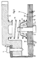
- Each terminal lug 26 is laminated on one side with the conductor foil 16 of a voltage polarity. 3 this is the positive voltage polarity.
- the terminal insulating film 151 has only one connection lug corresponding to the polarity mentioned.
- the terminal lugs 26 are each folded over at the end, so that the conductor foil 16 lies on the outside in the area of this fold 28. These folds 28 are placed one above the other and placed on the contact pin 11 of the corresponding polarity. Conductor foils of adjacent insulating foils thus lie on top of one another. This ensures a secure conductive connection.
- the contact pin 11 is fastened and fixed in the support plate 24.
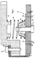
- the conductor foils of opposite polarity are led to the contact pin 10 via the connecting lugs 27, as shown in FIG. 4.
- an insulating film 152 has only one connecting lug 27.
- the folds 28 are provided at the end.
- the individual ceramic plates of the plate stack are electrically connected in parallel, so that each ceramic plate makes a precisely defined contribution to the opening force.
- a corresponding number of ceramic plates can provide any opening force.
- a desired characteristic curve can also be achieved by appropriate dimensioning of the individual ceramic plates.
Landscapes
- Engineering & Computer Science (AREA)
- Chemical & Material Sciences (AREA)
- Combustion & Propulsion (AREA)
- Mechanical Engineering (AREA)
- General Engineering & Computer Science (AREA)
- Fuel-Injection Apparatus (AREA)
Description
- Die Erfindung betrifft ein Kraftstoffeinspritzventil mit einem piezokeramischen Ventilkörper umfassend mehrere aufeinander geschichtete Keramikplatten mit je einer Leiterschicht auf jeder Seite jeder Keramikplatte und mit Spannungszuführungen zu den Leiterschichten.
- Ein Kraftstoffeinspritzventil der genannten Art ist in der DE-A 2 402 085 beschrieben. Dort sind benachbarte Keramikkörper beidseitig mit Leiterschichten ausgestattet und durch je eine Isolierschicht voneinander getrennt. Die Leiterschichten sind mit Elektroden verbunden. Ein Anschluss solcher Leiterschichten an Elektroden ist schwierig und aufwendig.
- Die DE-A 1 751 543 beschreibt ein Kraftstoffeinspritzventil, bei dem eine metallische Trägerplatte Keramikplatten trägt. Diese sind jeweils entgegengesetzt polarisiert, wodurch Unsymmetrien und Ungleichmässigkeiten der Stellwege bedingt sind. Auch hier ist der Spannungsanschluss an die Trägerplatte kritisch.
- Aufgabe der Erfindung ist eine mechanisch stabile und dauerhafte Kontaktierung der Leiterfolien zur Erzielung einer langen Lebensdauer.
- Diese Aufgabe wird nach der Erfindung dadurch gelöst, dass jede Keramikplatte auf einer Trägerplatte sitzt, dass zwischen jeder aus Keramikplatte und Trägerplatte bestehenden Einheit eine Isolierfolie mit auf jeder Seite angeordneten Leiterfolien als Leiterschichten angeordnet ist, dass jede Isolierfolie zwei Anschlussfahnen aufweist, dass jede Isolierfolie im Bereich einer Anschlussfahne einseitig mit einer Leiterfolie kaschiert ist und dass die zusammengehörigen Anschlussfahnen jeweils mit einem Kontakt für die zugeordneten Kontaktfolien verbunden sind.
- Die Erfindung unterscheidet sich insofern vom Stand der Technik, als die Leiterfolien für die Spannungszufuhr zu der Trägerplatte und zu der Keramikplatte jeweils mit einer Isolierfolie als Verbundfolie ausgebildet sind, so dass die Leiteranordnung einen festen Zusammenhalt hat. Dieses ermöglicht einen stabilen und dauerhaften Spannungsanschluss. Durch diese Anordnung lassen sich die einzelnen Keramikplatten in gleicher Ausrichtung betreiben, so dass eine genaue stellungsabhängige Steuerung möglich ist. Die Anschlussfahnen der lsolier- und Leiterfolien lassen sich leicht und dauerhaft kontaktieren.
- Eine sichere Kontaktierung wird dadurch erzielt, dass zusammengehörige Anschlussfahnen an ihren Enden mit aussenliegender Leiterfolie umgefaltet und auf einem Kontaktstift übereinander geschichtet sind. Durch diese Umfaltung ist gewährleistet, dass jeweils die Leiterfolien benachbarter Anschlussfahnen in unmittelbarem elektrischem Kontakt aufeinanderliegen, so dass eine sichere Kontaktierung gewährleistet ist.
- Zur Stabilisierung des Plattenstapels ist vorgesehen, dass der Plattenstapel aus Trägerplatten, Keramikplatten und Verbundfolien beidseitig durch eine Metallplatte abgeschlossen ist.
- Das Kraftstoffeinspritzventil ist ferner vorteilhaft dadurch gekennzeichnet, dass der Stapel auf einem eine Ventilnadel tragenden Ventilschaft sitzt und zwischen einer Feder und einem Anlagebund des Ventilschaftes eingeklemmt ist, dass der Stapel auf einem Bund des Ventilgehäuses liegt und mittels einer Druckfeder gegen diesen Bund in Schliessrichtung der Ventilnadel vorgespannt ist. Diese Anordnung ermöglicht eine vorteilhafte Konstruktion, indem der Plattenstapel am Rand innerhalb des Ventilgehäuses abgestützt und in Schliessrichtung der Ventilnadel vorgespannt wird.
- Damit eine einwandfreie Einstellung des Schliessdruckes und eine sichere Kontaktierung gewährleistet sind, ist vorgesehen, dass innerhalb des Ventilgehäuses eine Abstützplatte angeordnet ist, an der sich einerseits die Druckfeder abstützt und die andererseits die Kontaktstifte aufnimmt.
- Eine Ausführungsform der Erfindung wird im folgenden unter Bezugnahme auf die anliegenden Zeichnungen erläutert, in denen darstellen:
- Fig. 1 einen Axialschnitt durch ein Kraftstoffeinspritzventil nach der Erfindung,
- Fig. 2 einen Schnitt nach der Linie A-A in Fig. 1,
- Fig. 3 in vergrössertem Massstab einen Schnitt durch das Plattenpaket mit den Anschlussfahnen einer Polarität und
- Fig. 4 einen entsprechenden Schnitt durch das Plattenpaket mit den Anschlussfahnen entgegengesetzter Polarität.
- Das Kraftstoffeinspritzventil umfasst ein Ventilgehäuse 1 mit einem Deckel 2 und einer Einspritzdüse 3. Innerhalb der Einspritzdüse 3 befindet sich ein Einspritzkanal 4, der durch einen an einem Ventilschaft 6 sitzenden Ventilverschluss 5 abgeschlossen ist. Innerhalb des Deckels befindet sich ein Kraftstoffzufuhrkanal 7 und ein Filterkörper 8. Ausserdem ist eine Steckverbindung 9 mit zwei Kontaktstiften 10, 11 vorgesehen.
- Innerhalb des Ventilgehäuses 1 befindet sich der piezokeramische Ventilkörper 12, dessen Aufbau in Einzelheiten anhand der Fig. 3 und 4 erläutert wird. Der Ventilkörper 12 ist in Form eines Plattenpaketes aufgebaut. Man erkennt eine Mehrzahl von metallischen Trägerplatten 13, die jeweils eine Keramikplatte 14 tragen. Die Keramikplatte 14 ist mit der jeweiligen Trägerplatte 13 nach einer herkömmlichen Technik fest verbunden. Zwischen diesen Platten sind jeweils zur Kontaktierung Verbundfolien angeordnet, die aus einer Isolierfolie 15 mit beidseitig kaschierten metallischen Leiterfolien 16 bestehen. Im inneren Bereich des Plattenstapels sind die Isolierfolien 15 in der beschriebenen Weise doppelseitig kaschiert. Die jeweils endständigen Isolierfolien 151 und 152 sind nur einseitig mit einer Leiterfolie 16 kaschiert. Der Plattenstapel ist auf beiden Seiten durch eine Metallplatte 17, 18 abgeschlossen.
- Die Metallplatte 17 liegt einerseits auf einem Bund 19 des Ventilschaftes 6 und andererseits auf einem Bund 20 des Ventilgehäuses 1 auf. Im Bereich des Bundes 20 befinden sich Durchtrittskanäle 21 für den Kraftstoff. Auf der Metallplatte 18 stützt sich eine Federscheibe 22 ab, die in einer Rinne 23 des Ventilschaftes 6 gehalten ist. Diese Federscheibe 22 hält das Plattenpaket bzw. den Ventilkörper 12 zusammen, damit eine ausreichende elektrische Kontaktierung zwischen den Leiterfolien 6 und den Trägerplatten 13 bzw. Keramikplatten 14 gewährleistet ist.
- Innerhalb des Ventilgehäuses 1 ist eine Abstützplatte 24 angeordnet, an der sich eine Schraubendruckfeder 25 abstützt. Diese Schraubendruckfeder 25 liegt ebenfalls an dem Ventilkörper 12 an und stellt den Schliessdruck für den Ventilverschluss 5 bereit.
- Jede doppelseitig kaschierte Isolierfolie 15 weist zwei Anschlussfahnen 26, 27 auf. Jede Anschlussfahne 26 ist einseitig mit der Leiterfolie 16 einer Spannungspolarität kaschiert. Gemäss Fig. 3 ist dieses die positive Spannungspolarität. Die endständige Isolierfolie 151 besitzt nur eine Anschlussfahne entsprechend der genannten Polarität. Die Anschlussfahnen 26 sind am Ende jeweils umgefaltet, so dass im Bereich dieser Faltung 28 die Leiterfolie 16 auf der Aussenseite liegt. Diese Faltungen 28 werden übereinander gelegt und auf dem Kontaktstift 11 der entsprechenden Polarität aufgesetzt. Somit liegen jeweils Leiterfolien benachbarter Isolierfolien aufeinander. Dadurch ist eine sichere leitende Verbindung gewährleistet. Der Kontaktstift 11 ist in der Abstützplatte 24 befestigt und fixiert.
- Die Leiterfolien entgegengesetzter Polarität sind über die Anschlussfahnen 27 zu dem Kontaktstift 10 geführt, wie dies in Fig. 4 dargestellt ist. Auch hier weist eine Isolierfolie 152 nur eine Anschlussfahne 27 auf. Auch hier sind am Ende die Faltungen 28 vorgesehen.
- Die einzelnen Keramikplatten des Plattenstapels sind elektrisch parallel geschaltet, so dass jede Keramikplatte einen genau definierten Beitrag zur Öffnungskraft liefert. Man kann durch eine entsprechende Anzahl der Keramikplatten jede Öffnungskraft bereitstellen. Auch eine gewünschte Kennlinie lässt sich durch entsprechende Bemessung der einzelnen Keramikplatten verwirklichen. Eine Anordnung nach der Erfindung ermöglicht somit einen praktischen Aufbau eines Kraftstoffeinspritzventils mit piezokeramischem Ventilkörper. Die Anschlusstechnik mit Leiterfolien und Isolierfolien ermöglicht eine problemlose Montage. Man vermeidet so die Schwierigkeiten der herkömmlichen Kontaktierungsverfahren für Keramikplatten.
Claims (6)
Applications Claiming Priority (2)
| Application Number | Priority Date | Filing Date | Title |
|---|---|---|---|
| DE19853532660 DE3532660A1 (de) | 1985-09-13 | 1985-09-13 | Kraftstoffeinspritzventil |
| DE3532660 | 1985-09-13 |
Publications (2)
| Publication Number | Publication Date |
|---|---|
| EP0222097A1 EP0222097A1 (de) | 1987-05-20 |
| EP0222097B1 true EP0222097B1 (de) | 1988-12-07 |
Family
ID=6280840
Family Applications (1)
| Application Number | Title | Priority Date | Filing Date |
|---|---|---|---|
| EP86112456A Expired EP0222097B1 (de) | 1985-09-13 | 1986-09-09 | Kraftstoffeinspritzventil |
Country Status (4)
| Country | Link |
|---|---|
| US (1) | US4739929A (de) |
| EP (1) | EP0222097B1 (de) |
| JP (1) | JP2515991B2 (de) |
| DE (1) | DE3532660A1 (de) |
Families Citing this family (12)
| Publication number | Priority date | Publication date | Assignee | Title |
|---|---|---|---|---|
| DE3800203C2 (de) * | 1988-01-07 | 1997-08-14 | Atlas Fahrzeugtechnik Gmbh | Kraftstoffeinspritzventil |
| AU5270490A (en) * | 1989-03-07 | 1990-10-09 | Karl Holm | An atomizing nozzle device for atomizing a fluid and an inhaler |
| JPH06304059A (ja) * | 1991-11-22 | 1994-11-01 | Takaraya Bussan Kk | ツリー装飾用ランプ装置 |
| DE19849203A1 (de) * | 1998-10-26 | 2000-04-27 | Bosch Gmbh Robert | Brennstoffeinspritzventil |
| KR20020036230A (ko) * | 2000-11-09 | 2002-05-16 | 이계안 | 피에조 세라믹을 이용한 가변 엔티피 장치 |
| DE10147669A1 (de) * | 2001-09-27 | 2003-04-10 | Bosch Gmbh Robert | Piezoaktor zur Betätigung eines mechanischen Bauteils |
| DE10149914A1 (de) * | 2001-10-10 | 2003-04-24 | Bosch Gmbh Robert | Brennstoffeinspritzventil |
| US6739575B2 (en) | 2002-06-06 | 2004-05-25 | Caterpillar Inc | Piezoelectric valve system |
| US6811093B2 (en) * | 2002-10-17 | 2004-11-02 | Tecumseh Products Company | Piezoelectric actuated fuel injectors |
| US7077379B1 (en) | 2004-05-07 | 2006-07-18 | Brunswick Corporation | Fuel injector using two piezoelectric devices |
| DE102004041170A1 (de) * | 2004-08-25 | 2006-03-09 | Siemens Ag | Kraftstoffinjektor für eine Brennkraftmaschine sowie Verfahren zur Montage eines derartigen Kraftstoffinjektors |
| US10241500B2 (en) | 2015-08-10 | 2019-03-26 | Buerkert Werke Gmbh | Film transducer and actuator strip for a film transducer |
Family Cites Families (14)
| Publication number | Priority date | Publication date | Assignee | Title |
|---|---|---|---|---|
| CH429228A (de) * | 1964-12-10 | 1967-01-31 | Kistler Instrumente Ag | Piezoelektrischer Einbaukörper zum Einbau in einen piezoelektrischen Wandler |
| DE1751543A1 (de) * | 1968-06-15 | 1970-08-27 | Kloeckner Humboldt Deutz Ag | Elektrisch steuerbares Einspritzventil |
| NL7301617A (de) * | 1973-02-06 | 1974-08-08 | ||
| CA1125343A (en) * | 1977-12-06 | 1982-06-08 | Yoichi Kodera | Dielectric electro-mechanical transducer |
| US4160184A (en) * | 1978-01-09 | 1979-07-03 | The Singer Company | Piezoelectric actuator for a ring laser |
| FR2425599A1 (fr) * | 1978-05-10 | 1979-12-07 | Commissariat Energie Atomique | Vanne de reglage du debit d'un fluide |
| US4492360A (en) * | 1982-06-07 | 1985-01-08 | The Lee Company | Piezoelectric valve |
| US4471256A (en) * | 1982-06-14 | 1984-09-11 | Nippon Soken, Inc. | Piezoelectric actuator, and valve apparatus having actuator |
| US4528502A (en) * | 1982-10-01 | 1985-07-09 | General Electric Company | Current sensor |
| DE3313837A1 (de) * | 1983-04-16 | 1984-10-18 | Atlas Fahrzeugtechnik GmbH, 5980 Werdohl | Niederdruckeinspritzventil |
| JPS601369A (ja) * | 1983-06-16 | 1985-01-07 | Nippon Soken Inc | 燃料噴射弁 |
| EP0135665B1 (de) * | 1983-09-29 | 1991-07-03 | Siemens Aktiengesellschaft | Wandlerplatte für piezoelektrische Wandler und Vorrichtung zu deren Herstellung |
| US4635849A (en) * | 1984-05-03 | 1987-01-13 | Nippon Soken, Inc. | Piezoelectric low-pressure fuel injector |
| JPS60181996U (ja) * | 1984-05-11 | 1985-12-03 | 呉羽化学工業株式会社 | 電極端子取り出し構造体 |
-
1985
- 1985-09-13 DE DE19853532660 patent/DE3532660A1/de active Granted
-
1986
- 1986-09-09 EP EP86112456A patent/EP0222097B1/de not_active Expired
- 1986-09-09 US US06/905,517 patent/US4739929A/en not_active Expired - Lifetime
- 1986-09-12 JP JP61214248A patent/JP2515991B2/ja not_active Expired - Lifetime
Also Published As
| Publication number | Publication date |
|---|---|
| DE3532660C2 (de) | 1990-05-31 |
| EP0222097A1 (de) | 1987-05-20 |
| DE3532660A1 (de) | 1987-03-26 |
| US4739929A (en) | 1988-04-26 |
| JP2515991B2 (ja) | 1996-07-10 |
| JPS62111158A (ja) | 1987-05-22 |
Similar Documents
| Publication | Publication Date | Title |
|---|---|---|
| DE3800203C2 (de) | Kraftstoffeinspritzventil | |
| EP0222097B1 (de) | Kraftstoffeinspritzventil | |
| DE3839868C2 (de) | Thermistorbauelement | |
| WO2001091199A1 (de) | Piezoaktor | |
| DE19913271A1 (de) | Piezoelektrischer Aktor | |
| DE19945933C1 (de) | Piezoaktor mit isolationszonenfreier elektrischer Kontaktierung und Verfahren zu dessen Herstellung | |
| DE19909452C1 (de) | Piezoelektrischer Aktor | |
| DE19834461A1 (de) | Vielschicht-Piezoaktor | |
| CH662008A5 (de) | Saeulenbatterie mit elliptischem querschnitt. | |
| DE102016114566A1 (de) | Folienwandler und Aktorstreifen für einen Folienwandler | |
| EP1579515B1 (de) | Piezoaktor | |
| DE102013013402A1 (de) | Biegeelementanordnung sowie deren Verwendung | |
| EP2043170A2 (de) | Piezoaktormodul mit mehreren untereinander verbundenen Piezoaktoren und ein Verfahren zu dessen Herstellung | |
| DE3022907C2 (de) | Knopfzelle mit drei elektroden | |
| DE10260854A1 (de) | Piezoaktor | |
| DE102004016434A1 (de) | Elektrischer Fluidheizer | |
| EP0041917B1 (de) | Induktiver Spannungswandler für eine vollisolierte, metallgekapselte Hochspannungsschaltanlage | |
| EP0654135B1 (de) | Düsenstock für ölbrenner | |
| DE2755205C2 (de) | Gemeinsam einstellbares elektrisches Drehwiderstandspaar | |
| EP0520592A1 (de) | Wasserstoffspeicher für einen Plasmaschalter | |
| DE2640048A1 (de) | Aufzeichnungskopf fuer elektrographische aufzeichnungen | |
| DE102011120595A1 (de) | Piezoelement | |
| DE19928180B4 (de) | Piezoaktor | |
| WO2001024287A2 (de) | Innenelektroden für einen piezostapelaktor und zugehöriges herstellung-verfahren | |
| DE10243995B3 (de) | Mehrschichtiges Mikroventil mit integriertem elektrischem Antrieb |
Legal Events
| Date | Code | Title | Description |
|---|---|---|---|
| PUAI | Public reference made under article 153(3) epc to a published international application that has entered the european phase |
Free format text: ORIGINAL CODE: 0009012 |
|
| AK | Designated contracting states |
Kind code of ref document: A1 Designated state(s): AT BE CH DE FR GB IT LI NL SE |
|
| RBV | Designated contracting states (corrected) |
Designated state(s): FR GB IT |
|
| 17P | Request for examination filed |
Effective date: 19871117 |
|
| 17Q | First examination report despatched |
Effective date: 19880330 |
|
| GRAA | (expected) grant |
Free format text: ORIGINAL CODE: 0009210 |
|
| AK | Designated contracting states |
Kind code of ref document: B1 Designated state(s): FR GB IT |
|
| GBT | Gb: translation of ep patent filed (gb section 77(6)(a)/1977) | ||
| ET | Fr: translation filed | ||
| ITF | It: translation for a ep patent filed | ||
| PGFP | Annual fee paid to national office [announced via postgrant information from national office to epo] |
Ref country code: FR Payment date: 19890818 Year of fee payment: 4 |
|
| PLBE | No opposition filed within time limit |
Free format text: ORIGINAL CODE: 0009261 |
|
| STAA | Information on the status of an ep patent application or granted ep patent |
Free format text: STATUS: NO OPPOSITION FILED WITHIN TIME LIMIT |
|
| 26N | No opposition filed | ||
| PG25 | Lapsed in a contracting state [announced via postgrant information from national office to epo] |
Ref country code: GB Effective date: 19900909 |
|
| ITTA | It: last paid annual fee | ||
| GBPC | Gb: european patent ceased through non-payment of renewal fee | ||
| PG25 | Lapsed in a contracting state [announced via postgrant information from national office to epo] |
Ref country code: FR Effective date: 19910530 |
|
| REG | Reference to a national code |
Ref country code: FR Ref legal event code: ST |
|
| PG25 | Lapsed in a contracting state [announced via postgrant information from national office to epo] |
Ref country code: IT Free format text: LAPSE BECAUSE OF NON-PAYMENT OF DUE FEES;WARNING: LAPSES OF ITALIAN PATENTS WITH EFFECTIVE DATE BEFORE 2007 MAY HAVE OCCURRED AT ANY TIME BEFORE 2007. THE CORRECT EFFECTIVE DATE MAY BE DIFFERENT FROM THE ONE RECORDED. Effective date: 20050909 |