EP0222111A1 - Video-Magnetbandgerät - Google Patents
Video-Magnetbandgerät Download PDFInfo
- Publication number
- EP0222111A1 EP0222111A1 EP86112853A EP86112853A EP0222111A1 EP 0222111 A1 EP0222111 A1 EP 0222111A1 EP 86112853 A EP86112853 A EP 86112853A EP 86112853 A EP86112853 A EP 86112853A EP 0222111 A1 EP0222111 A1 EP 0222111A1
- Authority
- EP
- European Patent Office
- Prior art keywords
- tape
- magnetic tape
- head drum
- toothing
- elements
- Prior art date
- Legal status (The legal status is an assumption and is not a legal conclusion. Google has not performed a legal analysis and makes no representation as to the accuracy of the status listed.)
- Granted
Links
- 239000000969 carrier Substances 0.000 description 3
- 238000000034 method Methods 0.000 description 1
- 238000004804 winding Methods 0.000 description 1
Images


Classifications
-
- G—PHYSICS
- G11—INFORMATION STORAGE
- G11B—INFORMATION STORAGE BASED ON RELATIVE MOVEMENT BETWEEN RECORD CARRIER AND TRANSDUCER
- G11B15/00—Driving, starting or stopping record carriers of filamentary or web form; Driving both such record carriers and heads; Guiding such record carriers or containers therefor; Control thereof; Control of operating function
- G11B15/60—Guiding record carrier
- G11B15/66—Threading; Loading; Automatic self-loading
- G11B15/665—Threading; Loading; Automatic self-loading by extracting loop of record carrier from container
- G11B15/6653—Threading; Loading; Automatic self-loading by extracting loop of record carrier from container to pull the record carrier against drum
- G11B15/6655—Threading; Loading; Automatic self-loading by extracting loop of record carrier from container to pull the record carrier against drum using one loading ring, i.e. "C-type"
Definitions
- the invention relates to a video magnetic tape device with a device for the gradual entrainment of control elements by a drive element according to the preamble of claim 1.
- Video magnetic tape devices are known in which the magnetic tape is pulled out of a tape cassette with two tape winding spools and is placed in an inclined position around a part of a rotating head drum, the head drum being assigned at least one video magnetic head.
- the tape guiding elements required for guiding the magnetic tape are at least partially arranged on an annular carrier.
- the Carrier is placed around the head drum and can be driven in both directions of rotation. Since the magnetic tape is drawn around the head drum in the form of a loop, several tape guide elements or tape guide pins are required in order to avoid that the magnetic tape comes to lie one above the other in the loop area and in the remaining guide area.
- the various tape guide pins therefore assume different spacing positions from one another during the tape pull-in process in the area of the head drum between the starting position and the end position (tape guided around the head drum).
- tape guide pins are arranged on at least two carriers assigned to the head drum, and the carriers can be rotated separately into different end positions.
- other tape guide elements arranged on their own pivot levers are used in one device. The separate drive of these swivel levers is complex and requires precise control that is coordinated with the movement of the carrier.
- the object underlying the invention is an inexpensive device and control of tape guide elements, which are separated on a swivel Levers are arranged to provide, the drive being provided step by step by a drive element which consists of a control disk arranged in a ring around the head drum.
- FIG. 1 shows a simplified representation of a top view of a part of a video magnetic tape device 1, of which a magnetic tape cassette 2, a head drum 3 with an associated annular control disk 4, and various tape guide elements in the form of tape guide pins 5 to 8 are shown by the outline.
- the control disk 4 has an outer ring gear 10 and can be driven by a motor 11 in both directions of rotation. All parts are mounted directly or via control elements on a device chassis 12.
- the magnetic tape 13 which is located in the cassette, is gripped behind by the tape guide elements and can be pulled out of the cassette by them.
- the tape guide elements are preferably designed as vertically upright tape guide pins, the tape guide pins 5 and 6 being firmly placed on the control disk, and the guide pins 7, 8 and 9 each being attached to a swivel lever.
- the tape guide pin 9 is located on a pivot lever 14 which is provided with a ring gear 15 in the area of the bearing point.
- the ring gear 15 is in engagement with a drive wheel 16, which in turn is in engagement with the control disk 4.
- the control disk partially has an internal toothing 17 in the inner region, which, however, is provided by a slide area 18 is interrupted. If the control disc 4 is rotated by the drive motor in the direction of the arrow, the tape guide pins 5 and 6, which take the magnetic tape with them, move into a new position, and at the same time the drive wheel 16 rotates and this moves the pivoting lever 14, the tape guide pin, which is opposite to the direction of the arrow occupies a new position. Since the internal toothing 17 is attached to the control disk 4 only over a partial area, the pivoting lever is pivoted into a specific predetermined position and then remains in this position, since the drive wheel is prevented from rotating further by the sliding surface 18 of the control disk 4.
- Figure 2 shows the changed position of the tape guide pins 5 to 9 after turning the control disc.
- the magnetic tape 13 is pulled out of the cassette and partially placed around the head drum 3 and brought into a position in which the tape is still from other signal converters (audio head, erase head) can be scanned.
- the swivel levers assigned to the band guide pins 7 and 8 can be driven by the control disk in the same way as the swivel lever 14 on which the band guide pin 9 is seated.
- the drive wheel 16 rests on the sliding surface 18 of the control disk 4 and as shown in the drawing, is blocked or driven by the internal toothing 17 or the internal toothing region 17.
- the drive wheel 16 has a tooth arrangement in which every second tooth is shortened in the axial direction.
- the respectively axially shortened tooth projecting into the sliding surface of the control disk is exposed in that the sliding surface of the control disk is also shortened in the axial direction with respect to the toothed area.
Landscapes
- Adjustment Of The Magnetic Head Position Track Following On Tapes (AREA)
- Magnetic Heads (AREA)
- Developing Agents For Electrophotography (AREA)
Abstract
Description
- Die Erfindung bezieht sich auf ein Video-Magnetbandgerät mit einer Einrichtung zur schrittweisen Mitnahme von Steuerelementen durch ein Antriebselement gemäß dem Oberbegriff des Anspruchs 1.
- Es sind Video-Magnetbandgerät bekannt, bei denen das Magnetband aus einer Bandkassette mit zwei Bandwickelspulen herausgezogen und in Schräglage um einen Teil einer rotierenden Kopftrommel gelegt wird, wobei der Kopftrommel wenigstens ein Video-Magnetkopf zugeordnet ist. Zur Führung des Magnetbandes sind bei bekannten Bandführungseinrichtungen in Videogeräten die erforderlichen Bandführungselemente wenigstens teilweise auf einem ringförmigen Träger angeordnet. Der Träger ist um die Kopftrommel gelegt und in beiden Drehrichtungen antreibbar. Da das Magnetband in Form einer Schlaufe um die Kopftrommel gezogen wird, sind mehrere Bandführungselemente bzw. Bandführungsstifte erforderlich, damit vermieden wird, daß das Magnetband im Schlaufenbereich und im übrigen Führungsbereich übereinander zu liegen kommt. Die verschiedenen Bandführungsstifte nehmen daher während des Bandeinzugsvorganges im Bereich der Kopftrommel zwischen der Ausgangslage und der Endlage (Band um die Kopftrommel geführt) verschiedene Abstandspositionen zueinander ein. Somit können nicht alle Bandführungsstifte einem Träger fest zugeordnet werden. Es ist daher bekannt, daß Bandführungsstifte auf mindestens zwei der Kopftrommel zugeordneten Träger angeordnet sind, und die Träger getrennt in verschiedene Endstellungen gedreht werden können. Es ist auch bekannt, daß zusätzlich zu einem oder zwei ringförmigen und getrennt antreibbaren Trägern mit Bandführungselementen noch weitere Bandführungselemente auf eigenen Schwenkhebeln angeordnet in einem Gerät eingesetzt sind. Der getrennte Antrieb dieser Schwenkhebel ist aufwendig und bedarf einer genauen zeitlich mit der Bewegung des Trägers abgestimmten Steuerung.
- Die der Erfindung zugrundeliegende Aufgabe besteht darin, eine preiswerte Einrichtung und Ansteuerung von Bandführungselementen, die getrennt auf einem Schwenk hebel angeordnet sind, zu schaffen, wobei der Antrieb schrittweise durch ein Antriebselement, das aus einer ringförmig um die Kopftrommel drehbar angeordneten Steuerscheibe besteht, vorgesehen ist.
- Diese Aufgabe wird durch die kennzeichnenden Merkmale im Anspruch 1 gelöst.
- Die Unteransprüche zeigen Ausgestaltungen der Erfindung.
- Die Erfindung wird nachfolgend anhand der Zeichnungen erläutert.
- Fig. 1 ist eine vereinfachte Draufsicht auf eine Kopftrommel eines Video-Magnetbandgerätes mit einer Steuerscheibe zur Betätigung von Bandführungselementen sowie einer Kassette mit einem eingelegten Magnetband,
- Fig. 2 ist eine Ansicht ähnlich der Fig. 1, jedoch mit aus der Kassette herausgezogenem und teilweise um die Kopftrommel geführtem Magnetband,
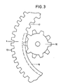
- Fig. 3 ist eine Teilansicht der Fig. 1, wobei der Eingriff eines Triebrades in eine Steuerscheibe vergrößert dargestellt ist.
- Die Figur 1 zeigt in vereinfachter Darstellung eine Draufsicht auf einen Teil eines Video-Magnetbandgerätes 1, von dem durch Umrißlinien erkennbar eine Magnetbandkassette 2, eine Kopftrommel 3 mit zugeordneter ringförmiger Steuerscheibe 4, sowie verschiedenen Bandführungselementen in Form von Bandführungsstiften 5 bis 8 gezeichnet sind. Die Steuerscheibe 4 weist einen äußeren Zahnkranz 10 auf und ist über einen Motor 11 in beiden Drehrichtungen antreibbar. Alle Teilse sind direkt oder über Steuerelemente auf einem Gerätechassis 12 montiert. Beim Auflegen einer Kassette 2 auf das Gerät 1 wird das Magnetband 13, das sich in der Kassette befindet, von den Bandführungselementen hinterfaßt und kann von diesen aus der Kassette herausgezogen werden. Die Bandführungselemente sind vorzugsweise als senkrecht hochstehende Bandführungsstifte ausgeführt, wobei die Bandführungsstifte 5 und 6 auf der Steuerscheibe fest aufgesetzt sind, und die Führungstifte 7, 8 und 9 je auf einem Schwenkhebel befestigt sind.
- Der Bandführungsstift 9 befindet sich auf einem Schwenkhebel 14, der im Bereich der Lagerstelle mit einem Zahnkranz 15 versehen ist. Der Zahnkranz 15 ist in Eingriff zu einem Triebrad 16, das sich wiederum in Eingriff zur Steuerscheibe 4 befindet. Die Steuerscheibe weist im inneren Bereich teilweise eine Innenverzahnung 17 auf, die jedoch durch eine Gleit fläche 18 unterbrochen ist. Wird die Steuerscheibe 4 durch den Antriebsmotor in Pfeilrichtung gedreht, so wandern die Bandführungsstifte 5 und 6, die das Magnetband mitnehmen, in eine neue Position, und gleichzeitig dreht sich das Triebrad 16 und dieses bewegt über den Schwenkhebel 14 den Bandführungsstift, der entgegen der Pfeilrichtung eine neue Position einnimmt. Da die Innenverzahnung 17 nur über einen Teilbereich an der Steuerscheibe 4 angebracht ist, wird der Schwenkhebel in eine bestimmte vorgegebene Stellung verschwenkt und verbleibt dann in dieser Lage, da das Triebrad durch die Gleitfläche 18 der Steuerscheibe 4 am Weiterdrehen gehindert wird.
- Die Figur 2 zeigt die nach dem Verdrehen der Steuerscheibe veränderte Lage der Bandführungsstifte 5 bis 9. Mit der Bewegung der Bandführungsstifte wird das Magnetband 13 aus der Kassette herausgezogen und teilweise um die Kopftrommel 3 gelegt sowie in eine Position gebracht, in der das Band noch von anderen Signalwandlern (Audiokopf, Löschkopf) abgetastet werden kann. Die den Bandführungsstiften 7 und 8 zugeordneten Schwenkhebel können durch die Steuerscheibe in gleicher Weise angetrieben werden wie der Schwenkhebel 14, auf dem der Bandführungsstift 9 aufsitzt.
- Aus der Figur 3 ist zu erkennen, wie das Triebrad 16 an der Gleitfläche 18 der Steuerscheibe 4 anliegt und, wie in der Zeichnung dargestellt, gesperrt ist oder durch die Innenverzahnung 17 bzw. Innen-Verzahnungsbereich 17 angetrieben wird. Das Triebrad 16 weist, wie bei sogenannten Springrollenenzählwerken bekannt, eine Zahnanordnung auf, bei der jeder zweite Zahn in axialer Richtung verkürzt ist. Der jeweils axialverkürzte und in die Gleitfläche der Steuerscheibe hineinragende Zahn ist dadurch freiliegend, daß die Gleitfläche der Steuerscheibe gegenüber dem verzahnten Bereich ebenfalls in axialer Richtung verkürzt ist.
Claims (4)
Priority Applications (1)
| Application Number | Priority Date | Filing Date | Title |
|---|---|---|---|
| AT86112853T ATE52868T1 (de) | 1985-11-15 | 1986-09-17 | Video-magnetbandgeraet. |
Applications Claiming Priority (2)
| Application Number | Priority Date | Filing Date | Title |
|---|---|---|---|
| DE3540512 | 1985-11-15 | ||
| DE19853540512 DE3540512A1 (de) | 1985-11-15 | 1985-11-15 | Video-magnetbandgeraet |
Publications (2)
| Publication Number | Publication Date |
|---|---|
| EP0222111A1 true EP0222111A1 (de) | 1987-05-20 |
| EP0222111B1 EP0222111B1 (de) | 1990-05-16 |
Family
ID=6286049
Family Applications (1)
| Application Number | Title | Priority Date | Filing Date |
|---|---|---|---|
| EP86112853A Expired - Lifetime EP0222111B1 (de) | 1985-11-15 | 1986-09-17 | Video-Magnetbandgerät |
Country Status (3)
| Country | Link |
|---|---|
| EP (1) | EP0222111B1 (de) |
| AT (1) | ATE52868T1 (de) |
| DE (2) | DE3540512A1 (de) |
Citations (4)
| Publication number | Priority date | Publication date | Assignee | Title |
|---|---|---|---|---|
| GB2020879A (en) * | 1978-05-05 | 1979-11-21 | Philips Nv | Recording and/or playback apparatus |
| US4264937A (en) * | 1978-05-05 | 1981-04-28 | U.S. Philips Corporation | Magnetic tape guide alignment device |
| EP0068746A2 (de) * | 1981-06-24 | 1983-01-05 | Matsushita Electric Industrial Co., Ltd. | Magnetisches Aufnahme- und Wiedergabegerät |
| EP0105501A2 (de) * | 1982-10-01 | 1984-04-18 | Hitachi, Ltd. | Magnetisches Aufnahme- und Wiedergabegerät |
Family Cites Families (1)
| Publication number | Priority date | Publication date | Assignee | Title |
|---|---|---|---|---|
| JPS61242364A (ja) * | 1985-04-19 | 1986-10-28 | Hitachi Ltd | 記録再生装置の駆動力伝達機構 |
-
1985
- 1985-11-15 DE DE19853540512 patent/DE3540512A1/de not_active Withdrawn
-
1986
- 1986-09-17 EP EP86112853A patent/EP0222111B1/de not_active Expired - Lifetime
- 1986-09-17 AT AT86112853T patent/ATE52868T1/de not_active IP Right Cessation
- 1986-09-17 DE DE8686112853T patent/DE3671312D1/de not_active Expired - Lifetime
Patent Citations (4)
| Publication number | Priority date | Publication date | Assignee | Title |
|---|---|---|---|---|
| GB2020879A (en) * | 1978-05-05 | 1979-11-21 | Philips Nv | Recording and/or playback apparatus |
| US4264937A (en) * | 1978-05-05 | 1981-04-28 | U.S. Philips Corporation | Magnetic tape guide alignment device |
| EP0068746A2 (de) * | 1981-06-24 | 1983-01-05 | Matsushita Electric Industrial Co., Ltd. | Magnetisches Aufnahme- und Wiedergabegerät |
| EP0105501A2 (de) * | 1982-10-01 | 1984-04-18 | Hitachi, Ltd. | Magnetisches Aufnahme- und Wiedergabegerät |
Also Published As
| Publication number | Publication date |
|---|---|
| DE3540512A1 (de) | 1987-05-21 |
| EP0222111B1 (de) | 1990-05-16 |
| DE3671312D1 (de) | 1990-06-21 |
| ATE52868T1 (de) | 1990-06-15 |
Similar Documents
| Publication | Publication Date | Title |
|---|---|---|
| DE69229487T2 (de) | Antriebsvorrichtung für einen Ladestift | |
| DE2904983A1 (de) | Magnetaufzeichnungs- und wiedergabevorrichtung | |
| DE2636169C3 (de) | Magnetbandkassette | |
| DE3507660C2 (de) | ||
| DE3442260C2 (de) | ||
| DE2046494A1 (de) | Magnetbandfuhrungsvorrichtung fur Magnetbandgerate | |
| DE3719572C2 (de) | ||
| DE2536962C2 (de) | Automatische Ausschaltvorrichtung in einem Magnetbandgerät | |
| EP0252330A2 (de) | Video-Magnetbandgerät | |
| EP0222111B1 (de) | Video-Magnetbandgerät | |
| EP0223952B1 (de) | Einrichtung für ein Video-Magnetbandgerät zur bedarfsweisen Mitnahme von Steuerelementen | |
| DE3632460C2 (de) | ||
| DE2705615A1 (de) | Steuertaste fuer bandgeraete | |
| DE2407277A1 (de) | Drehbarer tonkopf fuer tonbandgeraete | |
| DE3718970A1 (de) | Bandlademechanismus fuer ein magnetbandaufzeichnungs- und wiedergabegeraet | |
| DE3688865T2 (de) | Kassettenaufnahme- und Wiedergabegerät. | |
| DE3545218A1 (de) | Video-magnetbandgeraet | |
| DE4403911B4 (de) | Kopftrommel- und Bandtransport-Antriebsvorrichtung für einen Videorecorder | |
| DE3626569A1 (de) | Magnetbandaufzeichnungs- und/oder -wiedergabegeraet | |
| DE69002753T2 (de) | Aufbau eines elektrischen Schiebedaches. | |
| EP0215199A2 (de) | Vorrichtung zum An- und Abkoppeln von Steuerelementen in einem Video-Magnetbandgerät | |
| EP0199068A1 (de) | Vorrichtung zur Führung eines Magnetbandes über Bandführungsrollen in einem Videomagnetbandgerät | |
| DE2411358C2 (de) | Vorrichtung zum Herausziehen, Zurückführen und Anlegen eines Magnetbandes an die Kopftrommel in einem Magnetaufzeichnungs- und/oder -wiedergabegerät mit Bandkassette | |
| EP0198116A1 (de) | Vorrichtung zur Führung eines Magnetbandes in einem Video-Magnetbandgerät | |
| DE69118677T2 (de) | Vorrichtung zum Öffnen eines Protektionselementes in einer Magnetbandkassette |
Legal Events
| Date | Code | Title | Description |
|---|---|---|---|
| PUAI | Public reference made under article 153(3) epc to a published international application that has entered the european phase |
Free format text: ORIGINAL CODE: 0009012 |
|
| AK | Designated contracting states |
Kind code of ref document: A1 Designated state(s): AT CH DE FR GB IT LI |
|
| 17P | Request for examination filed |
Effective date: 19871020 |
|
| 17Q | First examination report despatched |
Effective date: 19890314 |
|
| GRAA | (expected) grant |
Free format text: ORIGINAL CODE: 0009210 |
|
| AK | Designated contracting states |
Kind code of ref document: B1 Designated state(s): AT CH DE FR GB IT LI |
|
| REF | Corresponds to: |
Ref document number: 52868 Country of ref document: AT Date of ref document: 19900615 Kind code of ref document: T |
|
| GBT | Gb: translation of ep patent filed (gb section 77(6)(a)/1977) | ||
| REF | Corresponds to: |
Ref document number: 3671312 Country of ref document: DE Date of ref document: 19900621 |
|
| ET | Fr: translation filed | ||
| ITF | It: translation for a ep patent filed | ||
| PLBE | No opposition filed within time limit |
Free format text: ORIGINAL CODE: 0009261 |
|
| STAA | Information on the status of an ep patent application or granted ep patent |
Free format text: STATUS: NO OPPOSITION FILED WITHIN TIME LIMIT |
|
| 26N | No opposition filed | ||
| ITTA | It: last paid annual fee | ||
| PGFP | Annual fee paid to national office [announced via postgrant information from national office to epo] |
Ref country code: GB Payment date: 19920907 Year of fee payment: 7 |
|
| PG25 | Lapsed in a contracting state [announced via postgrant information from national office to epo] |
Ref country code: GB Effective date: 19930917 |
|
| GBPC | Gb: european patent ceased through non-payment of renewal fee |
Effective date: 19930917 |
|
| REG | Reference to a national code |
Ref country code: FR Ref legal event code: DL |
|
| REG | Reference to a national code |
Ref country code: CH Ref legal event code: PFA Free format text: GRUNDIG E.M.V. ELEKTRO- MECHANISCHE VERSUCHSANSTALT MAX GRUNDIG GMBH & CO. KG |
|
| REG | Reference to a national code |
Ref country code: FR Ref legal event code: CD |
|
| PGFP | Annual fee paid to national office [announced via postgrant information from national office to epo] |
Ref country code: CH Payment date: 19960911 Year of fee payment: 11 |
|
| PGFP | Annual fee paid to national office [announced via postgrant information from national office to epo] |
Ref country code: FR Payment date: 19960927 Year of fee payment: 11 |
|
| PGFP | Annual fee paid to national office [announced via postgrant information from national office to epo] |
Ref country code: AT Payment date: 19960930 Year of fee payment: 11 |
|
| REG | Reference to a national code |
Ref country code: CH Ref legal event code: PFA Free format text: GRUNDIG E.M.V. ELEKTRO- MECHANISCHE VERSUCHSANSTALT MAX GRUNDIG GMBH & CO. KG TRANSFER- GRUNDIG AG |
|
| PG25 | Lapsed in a contracting state [announced via postgrant information from national office to epo] |
Ref country code: AT Free format text: LAPSE BECAUSE OF NON-PAYMENT OF DUE FEES Effective date: 19970917 |
|
| PG25 | Lapsed in a contracting state [announced via postgrant information from national office to epo] |
Ref country code: LI Free format text: LAPSE BECAUSE OF NON-PAYMENT OF DUE FEES Effective date: 19970930 Ref country code: FR Free format text: THE PATENT HAS BEEN ANNULLED BY A DECISION OF A NATIONAL AUTHORITY Effective date: 19970930 Ref country code: CH Free format text: LAPSE BECAUSE OF NON-PAYMENT OF DUE FEES Effective date: 19970930 |
|
| REG | Reference to a national code |
Ref country code: CH Ref legal event code: PL |
|
| REG | Reference to a national code |
Ref country code: FR Ref legal event code: ST |
|
| PG25 | Lapsed in a contracting state [announced via postgrant information from national office to epo] |
Ref country code: IT Free format text: LAPSE BECAUSE OF NON-PAYMENT OF DUE FEES;WARNING: LAPSES OF ITALIAN PATENTS WITH EFFECTIVE DATE BEFORE 2007 MAY HAVE OCCURRED AT ANY TIME BEFORE 2007. THE CORRECT EFFECTIVE DATE MAY BE DIFFERENT FROM THE ONE RECORDED. Effective date: 20050917 |
|
| PGFP | Annual fee paid to national office [announced via postgrant information from national office to epo] |
Ref country code: DE Payment date: 20051005 Year of fee payment: 20 |