EP0222130B1 - Insbesondere Ablagezwecken dienendes tragfähiges und standfestes, insbesondere vertikal belastbares Möbelstück aus faltbarem Material, insbesondere Wellpappe - Google Patents
Insbesondere Ablagezwecken dienendes tragfähiges und standfestes, insbesondere vertikal belastbares Möbelstück aus faltbarem Material, insbesondere Wellpappe Download PDFInfo
- Publication number
- EP0222130B1 EP0222130B1 EP86113420A EP86113420A EP0222130B1 EP 0222130 B1 EP0222130 B1 EP 0222130B1 EP 86113420 A EP86113420 A EP 86113420A EP 86113420 A EP86113420 A EP 86113420A EP 0222130 B1 EP0222130 B1 EP 0222130B1
- Authority
- EP
- European Patent Office
- Prior art keywords
- parts
- piece
- side walls
- connecting parts
- furniture according
- Prior art date
- Legal status (The legal status is an assumption and is not a legal conclusion. Google has not performed a legal analysis and makes no representation as to the accuracy of the status listed.)
- Expired - Lifetime
Links
- 239000000463 material Substances 0.000 title claims abstract description 22
- 239000011087 paperboard Substances 0.000 title description 2
- 239000011111 cardboard Substances 0.000 claims abstract description 19
- 238000003860 storage Methods 0.000 claims abstract description 4
- 238000005304 joining Methods 0.000 claims abstract description 3
- 230000015572 biosynthetic process Effects 0.000 claims description 2
- 230000001174 ascending effect Effects 0.000 claims 1
- 238000005755 formation reaction Methods 0.000 claims 1
- 238000013461 design Methods 0.000 description 18
- 210000002105 tongue Anatomy 0.000 description 7
- 238000004026 adhesive bonding Methods 0.000 description 4
- 238000004804 winding Methods 0.000 description 4
- OKTJSMMVPCPJKN-UHFFFAOYSA-N Carbon Chemical compound [C] OKTJSMMVPCPJKN-UHFFFAOYSA-N 0.000 description 3
- 238000004519 manufacturing process Methods 0.000 description 3
- 238000010276 construction Methods 0.000 description 2
- 238000005520 cutting process Methods 0.000 description 2
- 230000000694 effects Effects 0.000 description 2
- 238000000034 method Methods 0.000 description 2
- 238000010422 painting Methods 0.000 description 2
- 238000012545 processing Methods 0.000 description 2
- 238000012549 training Methods 0.000 description 2
- 238000013459 approach Methods 0.000 description 1
- 238000011161 development Methods 0.000 description 1
- 210000005069 ears Anatomy 0.000 description 1
- 230000002349 favourable effect Effects 0.000 description 1
- 239000000835 fiber Substances 0.000 description 1
- 239000011888 foil Substances 0.000 description 1
- 238000003780 insertion Methods 0.000 description 1
- 230000037431 insertion Effects 0.000 description 1
- 238000009434 installation Methods 0.000 description 1
- 210000003739 neck Anatomy 0.000 description 1
- 210000001331 nose Anatomy 0.000 description 1
- 238000004806 packaging method and process Methods 0.000 description 1
- 239000002023 wood Substances 0.000 description 1
Images


Classifications
-
- A—HUMAN NECESSITIES
- A47—FURNITURE; DOMESTIC ARTICLES OR APPLIANCES; COFFEE MILLS; SPICE MILLS; SUCTION CLEANERS IN GENERAL
- A47B—TABLES; DESKS; OFFICE FURNITURE; CABINETS; DRAWERS; GENERAL DETAILS OF FURNITURE
- A47B43/00—Cabinets, racks or shelf units, characterised by features enabling folding of the cabinet or the like
- A47B43/02—Cabinets, racks or shelf units, characterised by features enabling folding of the cabinet or the like made of cardboard or the like
-
- A—HUMAN NECESSITIES
- A47—FURNITURE; DOMESTIC ARTICLES OR APPLIANCES; COFFEE MILLS; SPICE MILLS; SUCTION CLEANERS IN GENERAL
- A47B—TABLES; DESKS; OFFICE FURNITURE; CABINETS; DRAWERS; GENERAL DETAILS OF FURNITURE
- A47B2220/00—General furniture construction, e.g. fittings
- A47B2220/008—General furniture construction, e.g. fittings characterised by materials
- A47B2220/0083—Furniture made of sheet material
- A47B2220/0086—Furniture made of sheet material made of cardboard
Definitions
- the invention relates to a stable and stable, in particular vertically resilient piece of furniture, particularly for storage purposes, e.g. a shelf, made of foldable material, in particular corrugated cardboard, the piece of furniture being able to be assembled from a number of components that can be positively and interlocked with one another, at least some of which consist of flat, folded material blanks in the manner of a box element that is open at least on the front and has at least two side walls and possibly a rear wall can be erected and connecting parts such as tabs, tongues, noses, recesses, cutouts or the like for joining or locking together or in one another. has, in which at least one console or plate part can be inserted into the box element and is held there by means of corresponding connecting parts in a positive and / or non-positive manner.
- a known piece of furniture of this type (DE-GM 82 18 043) is provided as a stackable bottle rack.
- This includes shelf elements each in the form of a box open at the top with a bottom wall, a front wall, a rear wall and two side walls, as well as recesses for receiving bottle necks.
- the bottle rack can be assembled from a plurality of such rack elements, each of which can be erected from a plurality of foldable blanks.
- the corrugations of the corrugated cardboard material are oriented so that they run essentially vertically in the vertical walls, and the rear wall is stiffened by inserting an additional cut-out part intended.
- this bottle rack is naturally limited in its applicability to the function of storing bottle-shaped objects and should not meet any particularly high requirements in terms of design, i.e. the cut surfaces and connecting parts reveal the corrugated cardboard character of the processed material by protruding tabs, tongues or the like. form and the cut surfaces are exposed and visible, the increase in load capacity requires additional inserts such as the aforementioned second rear wall part.
- these shelves always show the character of corrugated cardboard, particularly due to the cut surfaces visible from the front, so that their use and installation possibilities in households are limited.
- the invention is based on the object of creating a multifunctional piece of furniture made of foldable material blanks which, taking advantage of the specific material properties of corrugated cardboard or similar material, such as load-bearing capacity in certain directions, foldability, mass processing, low weight and price, and easy assembly, gives the user the opportunity give the piece of furniture to vary within wide limits according to its ideas, especially in terms of its external appearance and for different purposes, while at the same time a resilience that can be increased in a multiplier manner in the relevant supporting areas as a result of the foldability of the material and by utilizing this foldability achieves an improved appearance in the main viewing direction should be.
- the box elements can preferably be designed as module components which are freely interchangeable with one another or with one another. In this way, one obtains an individually designed piece of furniture which can be put together for use without gluing, tacking or similar mechanical fastenings and which has wide variations in terms of size (different number of components to be joined) as well as the design by gluing, painting and the like.
- the piece of furniture according to the invention is a completely new way compared to previous attempts in this area, in that it no longer imitates the design elements of conventional furniture made of wood or similar material, but rather a species-specific one, based on the peculiarities of the foldable material, in particular corrugated cardboard and thus design with high resilience utilizing these properties (multiplier-like increase in load capacity through the profile-forming folds).
- the modular components can be designed either as triangular in horizontal section, comprising two side walls running at an angle to one another, or as square, two.
- Side walls and a rear wall each of which is open on a front into which at least one plate - Or console part with positive and / or non-positive connection can be used, which have the supporting parts as vertical posts with vertical parts with connecting parts for the module box element to be arranged above or below or for a closing element and into which the plate or console part as a front boundary of the side walls Locking the post can be used.
- any other layouts are also conceivable.
- Such a shelf can advantageously have, as the upper end for a number of stacked module components, a end element with post-shaped connecting parts for connection to the adjacent box element located underneath and, if appropriate, a cover element to be arranged thereon. From this you can see the possible variations with regard to the desired size or height of the shelf.
- the end element in the upper region of its post-shaped connecting parts can be formed with connecting parts for the positionally stable reception of a horizontal cover element or can have side walls with upper edges inclined from the post, as well as laterally and in the upper region the post-shaped connecting parts with connecting parts for the positionally stable reception of an inclined cover element.
- the cover element can be provided as a foldable part that can be subjected to high surface loads and has a multilayer surface configuration, which additionally has web-like edges that increase the load-bearing capacity.
- corrugated cardboard or similar foldable material low weight, simple mass production, favorable transport volume as a result of packaging as a ready-to-ship cut part kit, low costs, quick erection, do -it-yourself use
- Cardboard or laminated paper or cardboard materials with fiber routing, which may determine the strength ratios, combined in one, thereby giving a wide scope for creative ideas.
- the piece of furniture is composed of modular components, the shape of which is essentially determined by a jacket part formed from a cut part, which thus determines the main part of the technical and design requirements and into which other parts such as floors, when erecting (unfolding), Brackets, cover surfaces etc. can (can) be hooked in, the latter of course contributing to the dimensional stability as well as the design.
- the necessary connecting parts are at least largely concealed on the piece of furniture by visible surfaces, such as posts, walls, consoles, supporting webs and / or cover elements.
- the fact that the piece of furniture has supporting profiles produced by winding or folding is taken advantage of, in or with which other supporting parts such as e.g.
- the consoles can be hooked and / or locked by corresponding cutouts in the support profiles and arrangement of tongues, tabs or similar interlocking elements without additional mechanical fastening measures such as gluing, stitching or the like. requirement.
- these posts, webs etc. can be arranged in such a way that they cover the cut surfaces or edges of adjacent parts in a suitable manner.
- Such covering or covering of cut edges or connecting elements can, however, also be achieved by the already mentioned approaches, for example ear-shaped or lobe-shaped projections, arranged on the blanks at a corresponding point, which in turn can result in a special aesthetic effect in accordance with their respective design .
- corrugated cardboard cuts are all shown as examples of corrugated cardboard cuts and thus take particular account of the inherent characteristics of this material. If other, similar materials are used, their possible properties which differ from corrugated cardboard will have to be taken into account, without deviating from the principle of the invention.
- the corrugations of the corrugated cardboard blanks to be provided are arranged in such a way that optimum load-bearing ratios result, and are indicated in some sections of the drawings.
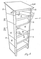
- a piece of furniture 1 is shown in the form of a standing desk-like shelf.
- This comprises a number of stacked or stacked module-like components 2, which are aligned with one another in plan, but can vary in height, as indicated by the lower components 2a and the higher element 2b.
- This gives the consumer numerous options when it comes to assembling the shelf and / or desk.
- the upper end is formed by a component 2 provided as the end element 23, the various training options of which will still be discussed.
- the modular components 2 are equipped with means for positive and / or non-positive connection, so that they can be placed on top of one another in a stable and secure manner.
- the components 2a, 2b have a box-shaped basic structure and, in the case of the piece of furniture shown in FIG. 1, form square-shaped modular, box elements 21a which can be interchanged as desired, the basic structure of which is shown in FIGS. 3a and 3b.
- These square box elements 21a essentially comprise two side walls 61 and a rear wall 62 connecting them and are open at the front.
- the side walls 61 determine with the rear wall 62 a jacket part 6, in this embodiment in the form of a square-shaped jacket part 601 in plan (Fig. 3a).
- the front edges or edges of the box element 21 a are provided as supporting parts 3 in the form of wound posts 31 formed in one piece with the side walls 61.
- brackets 7 are inserted, which are adapted to the plan shape of the box elements 21 a and are also locked in a positive and / or non-positive manner in the manner also described below.
- console elements 7 are also provided with support parts 3 in the form of double-layered support webs 32, while they have a console surface 71 for storing any items to be stored on the shelf, which can consist of single or multi-layer corrugated cardboard and on which the support webs 32 are formed in one piece are.
- a console is provided in the lower components 2a, while two such consoles are arranged in the higher components 2b.
- consoles 9 made of corrugated cardboard into the shelf with the help of the consoles 7, for which a training option is shown in FIGS. 6a-d, the various variants for such extensions being well known from the prior art are conceivable.
- the "tower" of box elements 21 a and 2a, 2b upwardly delimiting end element 23 is adapted to the box elements 21 in its basic structure and layout by adding side walls 61 and a rear wall 62 as well as front posts, but here in the form of post-shaped connecting parts 231 are formed.
- the blank or the jacket part for this connection part is shown in Fig. 4 and is explained in more detail below. Due to the design of the post-shaped connecting parts 231, it is possible to give the end element 23 and thus the shelf shown in FIG. 1 a desk-like appearance, in that a covering element 8 in the form of a plate element 81 can be fastened in the post-shaped connecting parts 231 Formation of the jacket part 6 with an inclined upper edge 233 on the end element side walls 232 (FIG.
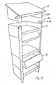
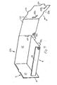
- FIG. 2 you can see the desk-like shelf of Fig. 1 with the end element 23 shortly before it is placed and connected to the uppermost box element 21 a, on which for receiving the post-shaped connecting parts 231 connecting parts 4 in the form of projections 44 on the posts 31 are provided are. Similar connecting parts 4 or projections 44 are located on all box elements 21, so that these, like the end element 23, can be easily fitted onto one another. In Fig. 2, a drawer 9 is also shown partially pulled out.
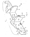
- 3a shows the basic structure of the jacket part 6, here in the form of a square jacket part 601 for the square box elements 21a and 2a, 2b. It is a substantially rectangular corrugated cardboard blank which is punched on a conventional corrugated cardboard processing system and provided with the lines 51 required for the folding in the form of scoring, scoring cutting lines or similar predetermined folding or folding lines which are well known in the industry becomes.
- the jacket part 601 includes the rear wall 62, hinged to the two side walls 61 and hinged to the latter, again foldable, the folding areas for the support parts 3, so here the posts 31.
- hooks 42 are provided on the brackets 7 or their supporting webs 32, which are formed as a result of folding in two layers, which in the manner specifically shown in FIG. 3 b have recesses 41 in the side walls 61 and the posts arranged at corresponding locations in corresponding locations 31 engage and thus lock the posts in their end position shown at C.
- the manner of insertion is indicated by the arrow in Fig. 3b.
- the locking takes place in the form and, due to the restoring forces of the wrapped post, in the simultaneous frictional connection.
- the result is an extremely compact, load-bearing and torsionally rigid component.
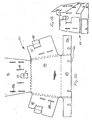
- FIG. 4 is an illustration similar to FIG. 3 of the blank (jacket part 6) for the end element 23, which is shown in position D in the flat state and in position E in the erected state. Since the same, already described elements are provided with the same reference numerals in this as in the further individual parts, this does not need to be discussed again, if there is agreement.
- the rear wall 62 carries side walls 232 designed for the special purpose of the end element 23. These are each equipped with a foldable upper part 234, which can be folded in via a crease line 5.
- the upper part 234 has an inclined upper edge 233 on which there are tongues 45 for mounting the cover element 8 or plate element 81.
- the upper parts 234 can be bent inwards by 90 ° , in which case tongues 45a protrude along the upper edges of the side walls 232 for the positive reception of the plate element 81. These are pre-punched accordingly.
- post-shaped connecting parts 231 are provided on the front side of the side walls 232 corresponding to the posts 31, which form a recess in the lower area for the box elements located thereunder or the post projection 44 thereof 46 wear while they have an angular recess 47 in the upper region and also have an inclined arrangement on the part corresponding to the projections 44, so that the wrapped post-shaped connecting part 231 results in the arrangement recognizable in position E.
- the projections 44a and the upper free corner of the side walls 232 have, after wrapping the post-shaped connecting parts 231, overlapping incisions 43 into which the web-like edge 83 of the plate element 81 can be inserted and in which it is held securely due to its shape and the restoring forces.
- FIG. 5a and 5b show a blank for the plate element 81 in the flat (FIG. 5a) and partially erected (FIG. 5b) state.
- This plate element is formed by two-layer measures, which are not described in more detail here, for which purpose three wing-like plate parts 85, 86 are hinged to a plate surface 84, which are folded inward and fastened to one another by means of tabs 87 which engage in cutouts 88 and are folded over . Further cutouts 88a, 88b provided in the wing-like plate parts 85, 86 serve to receive the tongues or 45a of the closing element 23 in the folded state.
- the plate surface 84 carries the web-like edge 83, which carries lateral edge wings 83a, which are folded inwards to give the double layer of the web-like edge 83 serving as a supporting part.
- Incisions 43a are provided here, which coincide with one another when the edge wings 83a are folded in. These incisions 43a engage in the incisions 43 on the end element 23 or on its post-shaped connecting part 231, in order to lock the end parts 231 on the one hand and to give the plate element 81 a firm fit on the other hand.
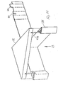
- Fig. 7 shows a variant for a component 2 with a square plan in the form of a box element 21 b, which is significantly simplified compared to the box element 21 a (Fig. 3a, b) and thus cheaper, but not so high in design value and a simple connection to neighboring elements.
- This more cost-effective construction is designed differently and more simply in terms of shape, since the posts are completely eliminated.
- the side walls are provided as supporting parts 3 as foldable double wall 63, which after being folded in are each locked in a cutout 621 in the rear wall 62 by means of an extension 631.
- this double wall 63 results in a sufficient load-bearing capacity, and in it there is a more simply designed console 7, which supports, supports or locks an upward support web 32, also designed as a double edge.
- console 7 which supports, supports or locks an upward support web 32, also designed as a double edge.
- foldable tabs 49a, b are arranged on the bracket, which engage in corresponding cutouts 632a, b in the side wall part 63 lying inside when erected.
- the cutout 632a is of an angular shape, so that the support web 32 projecting somewhat beyond the side edge of the console is also received in it. This also results in a locking of the double fold of the support web 32.
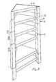
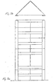
- the shelf shown in Fig. 8 or 9a, 9b differs from that shown in Fig. 1 to 7 only to the extent that the components 2a, 2b are triangular in plan here, ie triangular box elements 22, in the correspondingly shaped brackets 7 are used in the same way as described above.
- This triangular shelf has a correspondingly shaped cover element 8 in the form of a triangular plate element 82.
- the posts 31 are also slightly modified in that their end faces run essentially parallel to the support webs 32 of the brackets 7. As can be seen from FIGS.
- the principle of locking the brackets 7 in the casing part 602 defined by the two side walls 61 in a triangular plan in this exemplary embodiment is the same as for the square box element 21a, i.e. the winding of the posts 31 and locking the console 7 therein are carried out according to Fig. 3a and 3b. Since a rear wall is missing, a tab 610 which can be folded out inwards and on which the rear part of the console 7 rests can be punched on the rear at the joint of the two side walls 61.
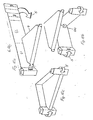
- FIG. 11 shows the end element 23 suitable for the triangular shelf with corresponding post-shaped connection parts 231 for receiving the triangular plate element 82 as a cover element, with corresponding projections 44 and notches 43 for the position-secure mounting of the plate element 82, which has notches 43b, in the area of the post-shaped connection parts 231 , are provided in the manner recognizable from the exploded view.
- all relevant connecting parts which are in the field of view can be covered by the posts 31 (embodiment FIGS. 1-4 and 8-11) or by the double wall 63 (embodiment in FIG. 7) , so that the technical measures for assembling the shelf or for connecting the individual parts of the components are not visible to the viewer. Rather, this offers an aesthetically pleasing shelf without any visible technical measures. If it is desired to allow connecting parts to penetrate the walls completely, the invention further provides, but not shown here, that such elements are then exaggeratedly wide as ears or rags be trained so that the design moment would hide the technical function.
- the individual components for the piece of furniture according to the invention can be conveniently packaged as flat blanks ready for dispatch, so that the buyer can be provided with a complete kit which he can easily assemble without additional technical aids and without special manual skills can.
- the possible different sizes and heights of the components result in numerous possible variations for use.
- the buyer is free to customize the piece of furniture by pasting or painting according to his own taste, although on the other hand it is possible for the manufacturer to manufacture and offer cuts with a decorative top layer.
- Another design variant consists in that post parts connected by a simple rear wall, between which only a narrow support bracket is arranged, are provided as a pair, connected by plates arranged between them, so that a four post around comprehensive tower can be set up as a free-standing shelf.
Landscapes
- Assembled Shelves (AREA)
- Laminated Bodies (AREA)
- Table Devices Or Equipment (AREA)
- Hydrogenated Pyridines (AREA)
- Tents Or Canopies (AREA)
- Cartons (AREA)
- Table Equipment (AREA)
Priority Applications (1)
| Application Number | Priority Date | Filing Date | Title |
|---|---|---|---|
| AT86113420T ATE56597T1 (de) | 1985-10-08 | 1986-09-30 | Insbesondere ablagezwecken dienendes tragfaehiges und standfestes, insbesondere vertikal belastbares moebelstueck aus faltbarem material, insbesondere wellpappe. |
Applications Claiming Priority (2)
| Application Number | Priority Date | Filing Date | Title |
|---|---|---|---|
| DE8528912U | 1985-10-08 | ||
| DE8528912U DE8528912U1 (de) | 1985-10-08 | 1985-10-08 | Insbesondere Ablagezwecken dienendes tragfähiges und standfestes, insbesondere vertikal belastbares Möbelstück aus faltbarem Material, insbesondere Wellpappe |
Publications (3)
| Publication Number | Publication Date |
|---|---|
| EP0222130A2 EP0222130A2 (de) | 1987-05-20 |
| EP0222130A3 EP0222130A3 (en) | 1987-09-16 |
| EP0222130B1 true EP0222130B1 (de) | 1990-09-19 |
Family
ID=6786155
Family Applications (1)
| Application Number | Title | Priority Date | Filing Date |
|---|---|---|---|
| EP86113420A Expired - Lifetime EP0222130B1 (de) | 1985-10-08 | 1986-09-30 | Insbesondere Ablagezwecken dienendes tragfähiges und standfestes, insbesondere vertikal belastbares Möbelstück aus faltbarem Material, insbesondere Wellpappe |
Country Status (4)
| Country | Link |
|---|---|
| EP (1) | EP0222130B1 (da) |
| AT (1) | ATE56597T1 (da) |
| DE (2) | DE8528912U1 (da) |
| DK (1) | DK475986A (da) |
Cited By (2)
| Publication number | Priority date | Publication date | Assignee | Title |
|---|---|---|---|---|
| DE102014012545A1 (de) | 2014-08-28 | 2016-03-03 | Kickpack Gmbh | Bausatz für einen Tisch sowie zugehöriger Tisch |
| DE202018004907U1 (de) * | 2018-10-23 | 2019-10-29 | Baypack Gmbh | Wurfspielgerät mit einem Spielfeld |
Families Citing this family (12)
| Publication number | Priority date | Publication date | Assignee | Title |
|---|---|---|---|---|
| DE8802882U1 (de) * | 1988-03-01 | 1989-04-06 | Europa Carton Ag, 2000 Hamburg | Aus zu Regal-Bauelementen auffaltbaren Zuschnitten faltbaren Materials wie insbesondere Wellpappe, Pappe od. dgl. zusammensetzbares Regal |
| DE3906936A1 (de) * | 1988-03-01 | 1989-09-14 | Europa Carton Ag | Aus zu regal-bauelementen auffaltbaren zuschnitten faltbaren materials wie insbesondere wellpappe, pappe od.dgl. zusammensetzbares regal |
| US5662399A (en) * | 1995-09-01 | 1997-09-02 | Doxey Furniture Corporation | Ready-to-assemble cabinet |
| FR2812526B1 (fr) * | 2000-08-04 | 2002-12-13 | Smurfit Socar Sa | Systeme d'exposition en vente d'articles divers, constitue d'elements en un materiau semi-rigide |
| DE202004021481U1 (de) * | 2004-08-21 | 2008-05-08 | Gaudes, Joachim | Verwendung von Hohlprofilen aus Pappe, Karton oder Hartpapier zur Herstellung von Möbeln |
| WO2008072088A1 (es) * | 2006-12-14 | 2008-06-19 | Ricardo Ceballos-Godefroy | Vitrina plegable |
| US9185984B2 (en) * | 2010-09-14 | 2015-11-17 | North Carolina Agricultural And Technical State University | Folded sheets of material for use as a structural member and assembly thereof |
| GB2509106A (en) * | 2012-12-20 | 2014-06-25 | Pollinator Ltd | An item of furniture assembled from flat panel components |
| DE202013103820U1 (de) * | 2013-08-23 | 2014-11-24 | Knappe + Lehbrink Promotion Gmbh | Bausatz für Möbel, Warendisplays oder transportable Bauten |
| US9345345B2 (en) * | 2013-10-31 | 2016-05-24 | International Paper Company | Corrugated display rack with cantilevered shelves |
| CN105559362A (zh) * | 2015-12-29 | 2016-05-11 | 常熟市大田包装材料有限公司 | 环保纸质家具 |
| SE545865C2 (en) * | 2021-02-26 | 2024-02-27 | Stora Enso Oyj | Kit of blanks for forming a desk and a desk formed of such kit of blanks |
Family Cites Families (4)
| Publication number | Priority date | Publication date | Assignee | Title |
|---|---|---|---|---|
| US3365258A (en) * | 1966-08-17 | 1968-01-23 | Downing Displays | Knock-down counter construction |
| DE2319595A1 (de) * | 1973-04-18 | 1974-11-14 | Ver Verpackungs Gmbh | Stapelbarer regalbaustein aus pappe |
| DE2520551A1 (de) * | 1975-05-09 | 1976-11-18 | Horst Kg Druck Und Verpackung | Dekorations- und regalsystem |
| US4373449A (en) * | 1980-01-14 | 1983-02-15 | Fellowes Manufacturing | Literature shelving |
-
1985
- 1985-10-08 DE DE8528912U patent/DE8528912U1/de not_active Expired
-
1986
- 1986-09-30 AT AT86113420T patent/ATE56597T1/de active
- 1986-09-30 DE DE8686113420T patent/DE3674338D1/de not_active Expired - Fee Related
- 1986-09-30 EP EP86113420A patent/EP0222130B1/de not_active Expired - Lifetime
- 1986-10-06 DK DK475986A patent/DK475986A/da not_active Application Discontinuation
Cited By (2)
| Publication number | Priority date | Publication date | Assignee | Title |
|---|---|---|---|---|
| DE102014012545A1 (de) | 2014-08-28 | 2016-03-03 | Kickpack Gmbh | Bausatz für einen Tisch sowie zugehöriger Tisch |
| DE202018004907U1 (de) * | 2018-10-23 | 2019-10-29 | Baypack Gmbh | Wurfspielgerät mit einem Spielfeld |
Also Published As
| Publication number | Publication date |
|---|---|
| DK475986A (da) | 1987-04-09 |
| EP0222130A2 (de) | 1987-05-20 |
| ATE56597T1 (de) | 1990-10-15 |
| EP0222130A3 (en) | 1987-09-16 |
| DK475986D0 (da) | 1986-10-06 |
| DE3674338D1 (de) | 1990-10-25 |
| DE8528912U1 (de) | 1986-01-30 |
Similar Documents
| Publication | Publication Date | Title |
|---|---|---|
| EP1459650B1 (de) | Regal aus einem knickbaren Material wie Pappe | |
| DE2533849A1 (de) | Faltschachtel | |
| EP0222130A2 (de) | Insbesondere Ablagezwecken dienendes tragfähiges und standfestes, insbesondere vertikal belastbares Möbelstück aus faltbarem Material, insbesondere Wellpappe | |
| DE3906936C2 (da) | ||
| DE3248290T1 (de) | Ausgangsprodukt für einen Sarg, und daraus hergestellter Sarg | |
| EP2033546A1 (de) | Sockel für Verkaufsaufsteller | |
| DE102015006399B4 (de) | Isolier- und Versandbehälter | |
| DE102018132416B4 (de) | Regalträger für ein offenes Regal | |
| DE29723900U1 (de) | Verkaufsaufsteller | |
| DE7819435U1 (de) | Verpackungsschachtel | |
| DE202020106165U1 (de) | Stapelbarer Warenträger | |
| DE202015001746U1 (de) | Regalboden und Pappregal | |
| DE29803040U1 (de) | Faltverpackung | |
| DE2526155A1 (de) | Raumgestaltungs-einrichtung | |
| DE19713472A1 (de) | Verkaufsaufsteller | |
| DE4301874A1 (de) | Baukasten aus flächigen Bauelementen | |
| DE19716735A1 (de) | Verkaufsaufsteller | |
| DE2520551A1 (de) | Dekorations- und regalsystem | |
| DE20119012U1 (de) | Verpackung für Puppen, Puppenzubehör und/o.dgl. | |
| EP0221342A1 (de) | Aus einer Anzahl von Zuschnitten faltbaren Materials, insbesondere Wellpappe, aufgerichteter Tisch | |
| EP2084997A1 (de) | Warendisplay | |
| DE102015210214A1 (de) | Pappregal | |
| DE202006009756U1 (de) | Verkaufsmodul, Display-Set und Zuschnitt-Set | |
| EP0850173A1 (de) | Verpackung, zuschnitt dafür und verfahren zu ihrer herstellung | |
| DE19728477A1 (de) | Behälterzuschnitt zur Herstellung eines Behälters |
Legal Events
| Date | Code | Title | Description |
|---|---|---|---|
| PUAI | Public reference made under article 153(3) epc to a published international application that has entered the european phase |
Free format text: ORIGINAL CODE: 0009012 |
|
| AK | Designated contracting states |
Kind code of ref document: A2 Designated state(s): AT BE CH DE FR GB IT LI LU NL SE |
|
| PUAL | Search report despatched |
Free format text: ORIGINAL CODE: 0009013 |
|
| AK | Designated contracting states |
Kind code of ref document: A3 Designated state(s): AT BE CH DE FR GB IT LI LU NL SE |
|
| 17P | Request for examination filed |
Effective date: 19880312 |
|
| 17Q | First examination report despatched |
Effective date: 19891110 |
|
| GRAA | (expected) grant |
Free format text: ORIGINAL CODE: 0009210 |
|
| AK | Designated contracting states |
Kind code of ref document: B1 Designated state(s): AT BE CH DE FR GB IT LI LU NL SE |
|
| PG25 | Lapsed in a contracting state [announced via postgrant information from national office to epo] |
Ref country code: IT Free format text: LAPSE BECAUSE OF FAILURE TO SUBMIT A TRANSLATION OF THE DESCRIPTION OR TO PAY THE FEE WITHIN THE PRESCRIBED TIME-LIMIT;WARNING: LAPSES OF ITALIAN PATENTS WITH EFFECTIVE DATE BEFORE 2007 MAY HAVE OCCURRED AT ANY TIME BEFORE 2007. THE CORRECT EFFECTIVE DATE MAY BE DIFFERENT FROM THE ONE RECORDED. Effective date: 19900919 Ref country code: GB Effective date: 19900919 Ref country code: SE Effective date: 19900919 Ref country code: BE Effective date: 19900919 Ref country code: FR Effective date: 19900919 Ref country code: NL Effective date: 19900919 |
|
| REF | Corresponds to: |
Ref document number: 56597 Country of ref document: AT Date of ref document: 19901015 Kind code of ref document: T |
|
| PG25 | Lapsed in a contracting state [announced via postgrant information from national office to epo] |
Ref country code: LI Effective date: 19900930 Ref country code: LU Free format text: LAPSE BECAUSE OF NON-PAYMENT OF DUE FEES Effective date: 19900930 Ref country code: CH Effective date: 19900930 Ref country code: AT Effective date: 19900930 |
|
| REF | Corresponds to: |
Ref document number: 3674338 Country of ref document: DE Date of ref document: 19901025 |
|
| PGFP | Annual fee paid to national office [announced via postgrant information from national office to epo] |
Ref country code: DE Payment date: 19901128 Year of fee payment: 5 |
|
| EN | Fr: translation not filed | ||
| NLV1 | Nl: lapsed or annulled due to failure to fulfill the requirements of art. 29p and 29m of the patents act | ||
| GBV | Gb: ep patent (uk) treated as always having been void in accordance with gb section 77(7)/1977 [no translation filed] | ||
| REG | Reference to a national code |
Ref country code: CH Ref legal event code: PL |
|
| PLBE | No opposition filed within time limit |
Free format text: ORIGINAL CODE: 0009261 |
|
| STAA | Information on the status of an ep patent application or granted ep patent |
Free format text: STATUS: NO OPPOSITION FILED WITHIN TIME LIMIT |
|
| 26N | No opposition filed | ||
| PG25 | Lapsed in a contracting state [announced via postgrant information from national office to epo] |
Ref country code: DE Effective date: 19920602 |