EP0222200A1 - Maschine zum Aufspulen von Magnetband auf Bandkassetten - Google Patents
Maschine zum Aufspulen von Magnetband auf Bandkassetten Download PDFInfo
- Publication number
- EP0222200A1 EP0222200A1 EP86114341A EP86114341A EP0222200A1 EP 0222200 A1 EP0222200 A1 EP 0222200A1 EP 86114341 A EP86114341 A EP 86114341A EP 86114341 A EP86114341 A EP 86114341A EP 0222200 A1 EP0222200 A1 EP 0222200A1
- Authority
- EP
- European Patent Office
- Prior art keywords
- magnetic tape
- tape
- machine according
- microprocessor
- feed
- Prior art date
- Legal status (The legal status is an assumption and is not a legal conclusion. Google has not performed a legal analysis and makes no representation as to the accuracy of the status listed.)
- Granted
Links
- 238000004804 winding Methods 0.000 title claims description 12
- 238000004026 adhesive bonding Methods 0.000 claims description 14
- 238000000034 method Methods 0.000 claims description 6
- 230000008878 coupling Effects 0.000 claims 1
- 238000010168 coupling process Methods 0.000 claims 1
- 238000005859 coupling reaction Methods 0.000 claims 1
- 238000005259 measurement Methods 0.000 description 3
- 230000000875 corresponding effect Effects 0.000 description 2
- 238000010586 diagram Methods 0.000 description 2
- 230000002596 correlated effect Effects 0.000 description 1
- 238000011156 evaluation Methods 0.000 description 1
- 230000006870 function Effects 0.000 description 1
- 230000001960 triggered effect Effects 0.000 description 1
Images

Classifications
-
- G—PHYSICS
- G11—INFORMATION STORAGE
- G11B—INFORMATION STORAGE BASED ON RELATIVE MOVEMENT BETWEEN RECORD CARRIER AND TRANSDUCER
- G11B23/00—Record carriers not specific to the method of recording or reproducing; Accessories, e.g. containers, specially adapted for co-operation with the recording or reproducing apparatus ; Intermediate mediums; Apparatus or processes specially adapted for their manufacture
- G11B23/02—Containers; Storing means both adapted to cooperate with the recording or reproducing means
- G11B23/113—Apparatus or processes specially adapted for the manufacture of magazines or cassettes, e.g. initial loading into container
Definitions
- the invention relates to a machine for winding magnetic tapes onto cassettes with start and end tape pieces.
- Such machines are known (DE-OS 27 07 391) in which the pretensioning tape, which is used to produce the start and end tape pieces, is pulled out of the cassette by means of a suction device and brought up to a cutting device.
- the leader tape is then attached to the tape to be wound and the magnetic tape to be wound, which is wound on a supply reel, is fed through guide elements to a cutting and gluing device.
- the cutting and gluing device can be designed such that a second cassette is prepared for loading with magnetic tape while a tape cassette is being wound up.
- the previously known machines also have the disadvantage that when the new feed spool is attached, the tapes can have different thicknesses. the different tape thickness is not taken into account, so that the winding. the desired length of a magnetic tape in a cassette may not be possible due to lack of space.
- a measuring device for measuring the length of the magnetic tape to be wound onto the cassette is attached to the feed to the cutting and gluing device, and a tachometer is attached to the feed reel, the measured values of which are fed to a microprocessor, to determine the thickness of the magnetic tape.
- the determination of the thickness of the magnetic tape is done in such a way that the values of two successive A ufspulabinsta an average value for the geweilingen Radiws de winding form on the feed roller, and this value is set with the average number of revolutions of both Aufspulabexcellent respect. This can easily be done by a microprocessor.
- the microprocessor also has an input device for the value of the size of the feed core.
- the length measuring device consists of a roller which lies on the guide of the magnetic tape and is connected to a disc, which as Tachometer acts.
- the arrangement of the tachometer on the roller on the guide of the magnetic tape, as well as the arrangement of the tachometer on the feed spools can also be used so that the pulses of the speed sensors of the feed spools via a circuit AND with the pulses of the sensors on the guide roller of the magnetic tape so can be connected that the switching on of the supply reel from which the magnetic tape is to be pulled is controlled.
- microprocessor it is advantageous to connect the microprocessor to a memory that stores the values that are given by the sensors to the microprocessor. This enables a comparison of the values measured in the current winding process with those of the previous winding process
- connection of the microprocessor and the memory to a test device is advantageous, which independently supplies combinations of the measured values to a data test memory or a display device.
- Fig. 1, 1 denotes the cassette to be spooled, which is fed to the machine by a feed device, not shown.
- the feeding device is arranged on the side.
- a loop of the pretensioning tape is pulled out by means of negative pressure and guided on the carriage of a cutting and gluing device.
- the slide 3 of the cutting and gluing device receives the magnetic tape to be wound up from a supply reel 5 via a cutting and gluing device 6, a loop guide 7 and fed to a roll 8.
- a speed sensor 10 is arranged on the roller 8.
- Speed sensors 14 are likewise arranged on the axes 11, 12 of the feed coils 5 and 9.
- the values measured by these sensors are fed to a microprocessor 13 (FIG. 2), which determines the length of the tape to be wound from the speed measured on the roller 8.
- the radii R 1 and R 2 of the bobbin after carrying out are determined by means of the microprocessor by means of the determined length L of the strip and by the speed of the bobbin from which the strip to be wound is removed in two successive bobbins according to the formula L: N x 2 determined by two consecutive unwinding operations. From these radii R 1 and R 2 , the average radius of the feed roll winding is determined by the microprocessor. This average radius is the mean of a cassette spool length.
- the mean speed is determined from the speed values of two successive spooling operations, and the mean value of the supply spool length is related to the mean speed.
- the value determined in the microprocessor in this way supplies the average thickness of the strip S.
- This value together with the length of the strip L and the value of the diameter ⁇ of the core 14 of the feed spools 5 or 9, serves as a control signal for changing the feed spool by the cutting and gluing device 6.
- This control of the changing device takes place in such a way that the quantity quoted determines the amount of tape that must still be present on the spool core in order to wind a cassette.
- This value is related to the speed so that if the length of the tape still present on the spool 14 is too small, i.e. the speed of the coil is too high, a control signal for changing to the second coil is triggered on the device 6.
- the determined values are also always fed to the memory SP.
- the microprocessor also serves to switch on the drive motor of the feed reel 5 or 9 from the number of revolutions of the reel 8 and the related number of revolutions of the reels 5 or 9, by means of a logic circuit (AND) at the start of the magnetic tape feed on the slide 3 cause. from the spool from which the magnetic tape is removed.
- a logic circuit AND
- the circuit is constructed in such a way that a program step is switched on which leads the tape to the carriage 3 when the tape contained on the rollers 5 or 9 is to be unwound. At the beginning of the change from one to the other spool, the entire program sequence is started.
- the length of the tape pretensioning tape. It is also possible to enter the length of the tape to be wound up as a fixed value using the keyboard 15. The sensor 10 on the roll then initiates a corresponding command, so that after this length of tape has passed, the magnetic tape is cut and the tape is attached to the second half of the pretensioning tape.
- a control device 16 connected to the microprocessor which serves as a data terminal. Measured values can be linked here so that the functions of the machine can be checked. The correlated values are stored in the terminal or displayed using a corresponding device (screen 17).
- the control device 16 is also constructed in such a way that external control makes it possible to display information in the general program flow. These can be coded error measurements, for example.
- a multiple connection 20 can also be provided for picking up the data
Landscapes
- Controlling Rewinding, Feeding, Winding, Or Abnormalities Of Webs (AREA)
- Automatic Tape Cassette Changers (AREA)
- Magnetic Record Carriers (AREA)
- Indexing, Searching, Synchronizing, And The Amount Of Synchronization Travel Of Record Carriers (AREA)
- Length Measuring Devices With Unspecified Measuring Means (AREA)
Abstract
Description
- Die Erfindung betrifft eine Maschine zum Aufspulen von Magnetbändern auf Kassetten mit Anfangs- und Endbandstücken.
- Es sind derartige Maschinen bekannt (DE-OS 27 07 391) bei denen das Vorspannband, das zur Herstellung der Anfangs- und Endbandstücke dient, mittels einer Saugvorrichtung aus der Kassette herausgezogen und an eine Schnittvorrichtung herangeführt wird. Das Vorspannband wird dann an das aufzuspulende Band angeheftet und das aufzuspulende Magnetband, das auf einer Zuführspule aufgewickelt ist, durch Führungselemente einer Schneid- und Klebevorrichtung zugeführt. Die Schneid- und Klebevorrichtung kann so ausgebildet sein, daß während dem Aufspulen einer Bandkassette eine zweite Kassette für das Laden mit Magnetband vorbereitet wird.
- Es ist schon bekannt, derartige Maschinen (Tapematic 2000) so auszurüsten, daß zwei Zuführspulen für Magnetband, das in die Kassetten eingespult wird, vorgesehen sind. In solchen Maschinen wird nach dem Auslaufen des Magnetbandes auf einer Zuführspule mittels einer Steuervorrichtung von einer Schneid- und Klebevorrichtung das Ende des Magnetbandes des letzten Spulvorganges vom Rest des auf der Spule noch befindlichen Bandes abgeschnitten und an den Anfang des Bandes der zweiten Spule geklebt. Durch diese Vorrichtung wird ein kontinuierliches Bespulen von Kassetten möglich, ohne daß eine Unterbrechung der Arbeitsabläufe der Maschine für den Wechsel einer Zuführspule notwendig ist. Die neue Zuführspule kann in der Vorrichtung so angeordnet werden, daß während der Entnahme von Magnetband von der zweiten Spule eine neue erste Spule aufgelegt werden kann, und der Anfang des Magnetbandes der neuen Spule bis zur bis zur Schneid- und Klebevorrichtung geführt wird.
- Diese bekannten Vorrichtungen weisen bisher keine ausreichende Steuerung auf. Das Wechseln von einer auf die andere Zuführspule kann nur in einem Augenblick erfolgen, in dem nicht mehr genug Magnetband auf der Zuführspule für den folgenden Spulvorgang vorhanden ist. In diesem Fall erfolgt eine Arbeitsunterbrechung der Maschine und ein Herausnehmen der Kassette, die nur teilweise mit Magnetband bespult ist.
- Die bisher bekannten Maschinen haben außerdem den Nachteil, daß bei der Anbringung der neuen Zuführspule, die Bänder verschiedener Dicke haben können. die verschiedene Banddicke nicht berücksichtigt wird, so daß die Aufspulung. der gewünschten Länge eines Magnetbandes in eine Kassette infolge Platzmangel nicht möglich sein kann.
- Es ist Aufgabe der Erfindung eine Steuervorrichtung zu schaffen, die aus wenigen Meßwerten die Dicke des Magnetbandes bestimmt, eine Messung der Länge des aufzuspulenden Bandes möglich macht und aus solchen Werten ein Steuersignal zum rechtzeitigen Wechseln der Zuführspule ableitet, mit gleichzeitiger Bewertung der gemessenen Werte bei Störfällen.
- Gemäß der Erfindung wird dies dadurch erreicht, daß an der Zuführung zur Schneid- und Klebevorrichtung eine Meßvorrichtung zur Messung der Länge des auf die Kassette zu spulenden Magnetbandes angebracht ist, und an der Zuführspule ein Drehzahlmesser angebracht ist, dessen gemessene Werte einen Mikroprozessor zugeführt werden, um die Dicke des Magnetbandes zu bestimmen. Die Bestimmung der Dicke des Magnetbandes geschieht in der Weise, daß die Werte zweier aufeinanderfolgender Aufspulabläufe einen mittleren Wert für den geweilingen Radiws de Wickel auf der Zuführrolle bilden, und dieser Wert mit der mittleren Umdrehungszahl beider Aufspulabläufe in Bezug gesetzt wird. Dies kann einfach durch einen Mikroprozessor bewerkstelligt werden.
- Der Mikroprozessor weist außerdem eine Eingabevorrichtung für den Wert der Größe des Zuführspulenkern auf.
- Die Längenmeßvorrichtung besteht aus einer Rolle die auf der Führung des Magnetbandes liegt und mit einer Scheibe verbunden ist, die als Drehzahlmesser fungiert. Die Anordnung des Drehzahlmessers an der Rolle auf der Führung des Magnetbandes, sowie die Anordnung 'der Drehzahlmesser auf den Zuführspulen kann außerdem so genutzt werden, daß die Impulse der Drehzahlsensoren der Zuführspulen über einen Schaltkreis AND mit den Impulsen der Sensoren auf der Führungsrolle des Magnetbands so in Verbindung gebracht werden, daß das Einschalten der Zuführspule von der das Magnetband abgezogen werden soll, gesteuert wird.
- Von Vorteil ist die Verbindung des Mikroprozessor mit einem Speicher, der die Werte, die von den Sensoren an den Mikroprozessor gegeben werden speichert. Hierdurch ist ein Vergleich der im gegenwärtigen Aufspulprozess gemessenen Werten mit denen des vorangegangenen Aufspulprozesses möglich
- Außerdem ist die Verbindung des Mikroprozessors und des Speichers mit einer Prüfvorrichtung von Vorteil, die selbstständig Kombinationen der gemessenen Werte einem Datenprüfspeicher oder einem anzeigenden Gerät zuführt.
- Ein Beispiel der Erfindung wird nachfolgend an Hand der beiliegenden Zeichnung beschrieben.
- Fig. 1 zeigt eine Gesamtansicht der Maschine
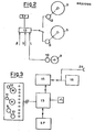
- Fig. 2 zeigt ein Blockschema der Steuerung
- Fig. 3 ein Blockschema des Mikroprozessors und der Speicher, sowie die Zuordnung der Sensoren für die Längenmessung und die Drehzahl.
- In Fig. 1 ist mit 1 die zu bespulende Kassette bezeichnet, die durch ein nicht dargestelltes Zuführgerät der Maschine zugeführt wird. Das Zuführgerät ist seitlich angeordnet. Durch eine Vorrichtung 2 wird eine Schleife des Vorspannbandes mittels Unterdruck herausgezogen und an den Schlitten einer Schneide- und Klebevorrichtung geführt. Parallel dazu wird dem Schlitten 3 der Schneide- und Klebevorrichtung das aufzuspulende Magnetband von einer Zuführspule 5 über eine Schneide- und Klebevorrichtung 6, einer Schleifenführung 7 und einer Rolle 8 zugeführt.
- Neben der Zuführspule 5 liegt eine weitere Zuführspule 9 deren Magnetband bis zur Schneid- und Klebevorrichtung 6 geführt wird.
- Gemäß der Erfindung ist auf der Rolle 8 ein Drehzahlsensor 10 angeordnet. Ebenso sind Drehzahlsensoren 14 auf den Achsen 11,12 der Zuführspulen 5 und 9 angeordnet. Die von diesen Sensoren gemessenen Werte werden einen Mikroprozessor 13 (Fig.2) zugeführt, der aus der an der Rolle 8 gemessenen Drehzahl die Länge des aufzuspulenden Bandes bestimmt. Außerdem werden mittels des Mikroprozessors durch die ermittelte Länge L des Bandes und durch die Drehzahl der Spule, von der das aufzuspulende Band entnommen wird, in zwei aufeinanderfolgenden Spulvorgängen gemäß der Formel L: N x 2 die Radien R1 und R2 der Spule nach Durchführung von zwei aufeinanderfolgenden Abspulvorgängen bestimmt. Aus diesen Radien R1 und R 2 wird durch den Mikroprozessor der mittlere Radius des Zuführrollenwickel ermittelt. Dieser mittlere Radius bildet das Mittel einer Kassettenspulenlänge.
- Aus den Drehzahlwerten zweier aufeinanderfolgender Spulenvorgänge wird die mittlere Drehzahl bestimmt, und der mittlere Wert der Zuführspulenlänge mit der mittleren Drehzahl in Bezug gesetzt.
- Der so im Mikroprozessor ermittelte Wert liefert die mittlere Dicke des Bandes S. Dieser Wert dient zusammen mit der Länge des Bandes L und dem Wert Durchmessers Ø des Kerns 14 der Zuführspulen 5 oder 9 als Steuersignal für das Wechseln der Zuführspule durch die Schneid-und Klebevorrichtung 6. Diese Steuerung der Wechselvorrichtung geschieht in der Weise, daß aus den zitierten Werten die Menge des Bandes, das auf den Spulenkern noch vorhanden-sein muß um eine Kassette zu bewickeln, ermittelt wird .
- Dieser Wert wird mit der Drehzahl in Beziehung gesetzt, sodaß, wenn die Länge des noch vorhandenen Bandes auf den Spulenkern 14 zu klein ist, d.h. die Drehzahl der Spule zu groß ist ein Steuersignal zum Wechsel zur zweiten Spule an die Vorrichtung 6 ausgelöst wird. Die ermittelten Werte werden außdem immer dem Speicher SP zugeführt.
- Der Mikroprozessor dient gleichzeitig dazu, aus den Umdrehungszahlen der Rolle 8 und der dazu im Verhältnis stehenden Umdrehungszahlen der Spulen 5 oder 9, durch einen logischen Schaltkreis (AND) am Anfang der Magnetbandzuführung an den Schlitten 3 das Einschalten des Antriebsmotors der Zuführspule 5 oder 9 zu bewirken. und zwar von der Spule von der das Magnetband abgenommen wird.
- Der Schaltkreis ist so aufgebaut, daß ein Programmschritt eingeschaltet wird,.der das Band zum Schlitten 3 hinführt, wenn das auf den Rollen 5-oder 9 enthaltene Band abgespult werden soll. Am Anfang der Umwechslung von einer auf die andere Spule wird also der gesamte Programmablauf in Gang gesetzt.
- Es ist auch möglich die Länge des aufzuspulenden Bandes als festen Wert durch die Tastatur 15 einzugeben. Der Sensor 10 an der Rolle leitet dann einen dementsprechenden Befehl ein, sodaß nach dem Vorbeilaufen dieser Bandlänge der Schnitt des Magnetbandes und das Anheften des Bandes an die zweite Hälfte des Vorspannbandes erfolgt.
- Wie in Fig. 3 gezeigt, ist außerdem eine mit dem Mikroprozessor verbundene Kontrollvorrichtung 16 vorgesehen, die als Datenterminal dient. Hier können gemessene Werte so miteinander verknüpft werden, daß eine Kontrolle der Funktionen der Maschine möglich ist. Die miteinander in Beziehung gesetzten Werte werden im Terminal gespeichert oder mittels eines entsprechenden Gerätes (Bildschirm 17) angezeigt.
- Die Kontrollvorrichtung 16 ist außerdem so aufgebaut, daß es durch Außensteuerung möglich ist, Informationen im allgemeinen Programmablauf anzuzeigen. Dies können z.B codierte Fehlermessungen sein . Es kann auch ein Mehrfachanschluß 20 zum abnehmen der Daten vorgesehen werden
Claims (10)
daß an einer Führungsrolle (8) der Zuführung zum Schlitten (3) der Schneid- und Klebevorrichtung eine Längenmeßeinrichtung (10) für das aufzuspulende Magnetband und an den Zuführungsspulen (5,9) Umdrehungszähler (14) angeordnet sind, deren Werte einem Mikroprozessor (13) für die Bestimmung der Dicke des Magnetbandes zugeführt werden
Priority Applications (1)
| Application Number | Priority Date | Filing Date | Title |
|---|---|---|---|
| AT86114341T ATE66764T1 (de) | 1985-10-17 | 1986-10-16 | Maschine zum aufspulen von magnetband auf bandkassetten. |
Applications Claiming Priority (2)
| Application Number | Priority Date | Filing Date | Title |
|---|---|---|---|
| IT2252585 | 1985-07-17 | ||
| IT22525/85A IT1185461B (it) | 1985-10-17 | 1985-10-17 | Macchina per la bobinatura di nastri magnetici in cassette per nastro |
Publications (2)
| Publication Number | Publication Date |
|---|---|
| EP0222200A1 true EP0222200A1 (de) | 1987-05-20 |
| EP0222200B1 EP0222200B1 (de) | 1991-08-28 |
Family
ID=11197432
Family Applications (1)
| Application Number | Title | Priority Date | Filing Date |
|---|---|---|---|
| EP86114341A Expired - Lifetime EP0222200B1 (de) | 1985-10-17 | 1986-10-16 | Maschine zum Aufspulen von Magnetband auf Bandkassetten |
Country Status (6)
| Country | Link |
|---|---|
| EP (1) | EP0222200B1 (de) |
| JP (1) | JPH07118175B2 (de) |
| AT (1) | ATE66764T1 (de) |
| DE (1) | DE3681116D1 (de) |
| ES (1) | ES2025552T3 (de) |
| IT (1) | IT1185461B (de) |
Cited By (2)
| Publication number | Priority date | Publication date | Assignee | Title |
|---|---|---|---|---|
| EP0281884A3 (en) * | 1987-03-10 | 1990-01-03 | Luciano Perego | Cassette winding apparatus and method for operating |
| WO1992022900A3 (en) * | 1991-06-17 | 1993-04-29 | Tape Automation Ltd | Improved double-pancake loader extractor |
Citations (5)
| Publication number | Priority date | Publication date | Assignee | Title |
|---|---|---|---|---|
| DE2157570A1 (de) * | 1971-11-19 | 1973-05-24 | Siemens Ag | Verfahren und vorrichtung zum messen der mittleren foliendicke in einem strekkenintervall eines bewegten folienbandes |
| DE2524537A1 (de) * | 1975-06-03 | 1976-12-16 | Phoenix Gummiwerke Ag | Vorrichtung zur laufenden dickenmessung bei werkstoffbahnen |
| DE2707391A1 (de) * | 1976-03-01 | 1977-09-15 | Aeg Telefunken Spa | Maschine zum aufspulen magnetischer baender in bandkassetten |
| WO1984001563A1 (en) * | 1982-10-07 | 1984-04-26 | James L King | Machine for loading cassettes |
| US4497454A (en) * | 1983-03-11 | 1985-02-05 | King Instrument Corporation | Tape loading machine |
-
1985
- 1985-10-17 IT IT22525/85A patent/IT1185461B/it active
-
1986
- 1986-10-16 AT AT86114341T patent/ATE66764T1/de not_active IP Right Cessation
- 1986-10-16 ES ES198686114341T patent/ES2025552T3/es not_active Expired - Lifetime
- 1986-10-16 EP EP86114341A patent/EP0222200B1/de not_active Expired - Lifetime
- 1986-10-16 DE DE8686114341T patent/DE3681116D1/de not_active Expired - Fee Related
- 1986-10-17 JP JP61245644A patent/JPH07118175B2/ja not_active Expired - Lifetime
Patent Citations (5)
| Publication number | Priority date | Publication date | Assignee | Title |
|---|---|---|---|---|
| DE2157570A1 (de) * | 1971-11-19 | 1973-05-24 | Siemens Ag | Verfahren und vorrichtung zum messen der mittleren foliendicke in einem strekkenintervall eines bewegten folienbandes |
| DE2524537A1 (de) * | 1975-06-03 | 1976-12-16 | Phoenix Gummiwerke Ag | Vorrichtung zur laufenden dickenmessung bei werkstoffbahnen |
| DE2707391A1 (de) * | 1976-03-01 | 1977-09-15 | Aeg Telefunken Spa | Maschine zum aufspulen magnetischer baender in bandkassetten |
| WO1984001563A1 (en) * | 1982-10-07 | 1984-04-26 | James L King | Machine for loading cassettes |
| US4497454A (en) * | 1983-03-11 | 1985-02-05 | King Instrument Corporation | Tape loading machine |
Cited By (4)
| Publication number | Priority date | Publication date | Assignee | Title |
|---|---|---|---|---|
| EP0281884A3 (en) * | 1987-03-10 | 1990-01-03 | Luciano Perego | Cassette winding apparatus and method for operating |
| WO1992022900A3 (en) * | 1991-06-17 | 1993-04-29 | Tape Automation Ltd | Improved double-pancake loader extractor |
| GB2269363A (en) * | 1991-06-17 | 1994-02-09 | Tape Automation Ltd | Improved double-pancake loader extractor |
| GB2269363B (en) * | 1991-06-17 | 1995-11-08 | Tape Automation Ltd | Apparatus and method for loading tape into cassettes |
Also Published As
| Publication number | Publication date |
|---|---|
| JPH07118175B2 (ja) | 1995-12-18 |
| IT1185461B (it) | 1987-11-12 |
| DE3681116D1 (de) | 1991-10-02 |
| JPS6313186A (ja) | 1988-01-20 |
| ES2025552T3 (es) | 1992-04-01 |
| EP0222200B1 (de) | 1991-08-28 |
| IT8522525A0 (it) | 1985-10-17 |
| ATE66764T1 (de) | 1991-09-15 |
Similar Documents
| Publication | Publication Date | Title |
|---|---|---|
| DE2313024C3 (de) | Anordnung zur Feststellung des sich nähernden Endes eines von einer ersten Speicherspule abgespulten Magnetbandes beim Umspulen von der ersten auf eine zweite Speicherspule bei einem Magnetbandgerät | |
| DE3914865C2 (de) | ||
| DE3438962A1 (de) | Faden-spulmaschine | |
| DE2632671C3 (de) | Spulenwickelmaschine mit mehreren Wickelstationen | |
| DE3733788C2 (de) | ||
| DE3923761C2 (de) | ||
| EP0016871B1 (de) | Verfahren und Vorrichtung zur Erzielung vorbestimmbarer und genauer Garnlängen auf Kreuzspulen | |
| EP0211875B1 (de) | Verfahren zur ermittlung der abgelaufenen und/oder noch zur verfügung stehenden spielzeit eines magnetbandes | |
| DE69107367T2 (de) | Kontrollgerät für Zwirnmaschinen. | |
| DE3206272C2 (de) | ||
| DE4222377C2 (de) | Verfahren und Vorrichtung zum Erfassen eines auf einer Kreuzspule angeordneten Fadenendes | |
| EP1151951A2 (de) | Verfahren zum Betreiben einer Kreuzspulen herstellenden Textilmaschine | |
| DE2215406A1 (de) | Einrichtung für die Bandtransportregelung eines Aufnahme/Wredergabegerätes | |
| EP0222200B1 (de) | Maschine zum Aufspulen von Magnetband auf Bandkassetten | |
| DE2853025A1 (de) | Verfahren und vorrichtung zur kontrolle und steuerung der uebertragung von bandfoermigem material von einer geber- auf eine empfaengerspule | |
| DE3806165A1 (de) | Wicklungssteuerverfahren fuer einen spulautomaten | |
| DE2643421A1 (de) | Verfahren und vorrichtung zum uebertragen eines garnfadens in einer automatischen spulmaschine | |
| EP0216260B1 (de) | Aufzeichnungs- und Wiedergabegerät mit einer Einrichtung zur Anzeige der Laufzeit der Restbandlänge | |
| DE3643772C2 (de) | ||
| DE2114033C3 (de) | Einrichtung zur Fadenlangenmessung | |
| EP0218264B1 (de) | Pneumatische Vorrichtung zum Bandspannen in einer Maschine zum Beladen von Magnetband auf Kassette | |
| EP1048598B1 (de) | Aufwickelvorrichtung, insbesondere für eine Wickelmaschine | |
| DE2438225A1 (de) | Vorrichtung zum bereitstellen von drahtschlaufen zur herstellung von bifilarwicklungen, insbesondere fuer fernmelderelais | |
| DE3743838A1 (de) | Anrufbeantworter | |
| DE1774056C (de) | Einrichtung zum Aufspulen von faden oder drahtförmigem Material |
Legal Events
| Date | Code | Title | Description |
|---|---|---|---|
| PUAI | Public reference made under article 153(3) epc to a published international application that has entered the european phase |
Free format text: ORIGINAL CODE: 0009012 |
|
| AK | Designated contracting states |
Kind code of ref document: A1 Designated state(s): AT BE CH DE ES FR GB LI |
|
| 17P | Request for examination filed |
Effective date: 19871008 |
|
| 17Q | First examination report despatched |
Effective date: 19890511 |
|
| GRAA | (expected) grant |
Free format text: ORIGINAL CODE: 0009210 |
|
| AK | Designated contracting states |
Kind code of ref document: B1 Designated state(s): AT BE CH DE ES FR GB LI |
|
| REF | Corresponds to: |
Ref document number: 66764 Country of ref document: AT Date of ref document: 19910915 Kind code of ref document: T |
|
| GBT | Gb: translation of ep patent filed (gb section 77(6)(a)/1977) | ||
| REF | Corresponds to: |
Ref document number: 3681116 Country of ref document: DE Date of ref document: 19911002 |
|
| ET | Fr: translation filed | ||
| REG | Reference to a national code |
Ref country code: CH Ref legal event code: PFA Free format text: ROBOTECNICA S.R.L. |
|
| REG | Reference to a national code |
Ref country code: ES Ref legal event code: FG2A Ref document number: 2025552 Country of ref document: ES Kind code of ref document: T3 |
|
| PG25 | Lapsed in a contracting state [announced via postgrant information from national office to epo] |
Ref country code: DE Effective date: 19920701 |
|
| PLBE | No opposition filed within time limit |
Free format text: ORIGINAL CODE: 0009261 |
|
| STAA | Information on the status of an ep patent application or granted ep patent |
Free format text: STATUS: NO OPPOSITION FILED WITHIN TIME LIMIT |
|
| 26N | No opposition filed | ||
| PGFP | Annual fee paid to national office [announced via postgrant information from national office to epo] |
Ref country code: FR Payment date: 19930927 Year of fee payment: 8 |
|
| PGFP | Annual fee paid to national office [announced via postgrant information from national office to epo] |
Ref country code: AT Payment date: 19931004 Year of fee payment: 8 |
|
| PGFP | Annual fee paid to national office [announced via postgrant information from national office to epo] |
Ref country code: BE Payment date: 19931013 Year of fee payment: 8 |
|
| PGFP | Annual fee paid to national office [announced via postgrant information from national office to epo] |
Ref country code: ES Payment date: 19931018 Year of fee payment: 8 |
|
| PGFP | Annual fee paid to national office [announced via postgrant information from national office to epo] |
Ref country code: CH Payment date: 19931117 Year of fee payment: 8 |
|
| PGFP | Annual fee paid to national office [announced via postgrant information from national office to epo] |
Ref country code: GB Payment date: 19941003 Year of fee payment: 9 |
|
| PG25 | Lapsed in a contracting state [announced via postgrant information from national office to epo] |
Ref country code: AT Effective date: 19941016 |
|
| PG25 | Lapsed in a contracting state [announced via postgrant information from national office to epo] |
Ref country code: ES Free format text: LAPSE BECAUSE OF NON-PAYMENT OF DUE FEES Effective date: 19941017 |
|
| PG25 | Lapsed in a contracting state [announced via postgrant information from national office to epo] |
Ref country code: LI Effective date: 19941031 Ref country code: CH Effective date: 19941031 Ref country code: BE Effective date: 19941031 |
|
| BERE | Be: lapsed |
Owner name: ROBOTECNICA S.R.L. Effective date: 19941031 |
|
| PG25 | Lapsed in a contracting state [announced via postgrant information from national office to epo] |
Ref country code: FR Effective date: 19950630 |
|
| REG | Reference to a national code |
Ref country code: CH Ref legal event code: PL |
|
| REG | Reference to a national code |
Ref country code: FR Ref legal event code: ST |
|
| PG25 | Lapsed in a contracting state [announced via postgrant information from national office to epo] |
Ref country code: GB Effective date: 19951016 |
|
| GBPC | Gb: european patent ceased through non-payment of renewal fee |
Effective date: 19951016 |
|
| REG | Reference to a national code |
Ref country code: ES Ref legal event code: FD2A Effective date: 19951113 |