EP0222275A2 - Machine à affranchir - Google Patents
Machine à affranchir Download PDFInfo
- Publication number
- EP0222275A2 EP0222275A2 EP86115113A EP86115113A EP0222275A2 EP 0222275 A2 EP0222275 A2 EP 0222275A2 EP 86115113 A EP86115113 A EP 86115113A EP 86115113 A EP86115113 A EP 86115113A EP 0222275 A2 EP0222275 A2 EP 0222275A2
- Authority
- EP
- European Patent Office
- Prior art keywords
- franking
- toothing
- engagement
- pawls
- movement
- Prior art date
- Legal status (The legal status is an assumption and is not a legal conclusion. Google has not performed a legal analysis and makes no representation as to the accuracy of the status listed.)
- Granted
Links
Images

Classifications
-
- G—PHYSICS
- G07—CHECKING-DEVICES
- G07B—TICKET-ISSUING APPARATUS; FARE-REGISTERING APPARATUS; FRANKING APPARATUS
- G07B17/00—Franking apparatus
- G07B17/00459—Details relating to mailpieces in a franking system
- G07B17/00508—Printing or attaching on mailpieces
-
- G—PHYSICS
- G07—CHECKING-DEVICES
- G07B—TICKET-ISSUING APPARATUS; FARE-REGISTERING APPARATUS; FRANKING APPARATUS
- G07B17/00—Franking apparatus
- G07B17/00459—Details relating to mailpieces in a franking system
- G07B17/00508—Printing or attaching on mailpieces
- G07B2017/00516—Details of printing apparatus
- G07B2017/00524—Printheads
- G07B2017/00548—Mechanical printhead
Definitions
- the invention relates to a franking machine according to the preamble of patent claim 1.
- a franking machine of the type in question is known from US Pat. No. 4,520,725.
- a specific franking value is set by means of electromagnetically driven adjusting plungers which push a rack forward in the direction of the franking head by means of a number of back and forth movements corresponding to the numerical value to be set. so that the respective stamp of the franking head is set to this numerical value.
- a locking pawl is provided, which engages behind each of the teeth of its drive teeth after each displacement movement of the rack and thus holds it in the set position against the pulling force of a return spring.
- Sensors arranged on the locking pawls report every movement of a locking pawl over a tooth of the drive toothing into a next tooth gap into the electronic display register.
- pawls are provided which engage in additional locking teeth of the rack during franking and thus secure the setting position of the type wheels.
- the return spring does not move the toothed rack back to its initial position or zero value position when a new franking value is set due to an inhibition of the sliding movement of a toothed rack that is improper or caused by manufacturing inaccuracies should be so that the newly set value is added to a residual value that is not entered in the register for used quantities. If the rack gets stuck in an intermediate position, the associated latch on the tip of a tooth of the drive remains gearing and the sensor reports the zero value of the value count to the register. If the drive of the franking machine is switched on for franking at such an intermediate position of the toothed rack, the pawl mechanism is also damaged, since its cam drive cannot move the pawls into a toothing gap in the locking toothing.
- the object of the invention is to increase the reliability of a franking machine of the type mentioned, so that the described error possibilities are reliably prevented. This object is achieved on the basis of the features of the characterizing part of patent claim 1.
- the dependent claims relate to advantageous embodiments of the invention.
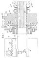
- FIG. 1 which corresponds to FIG. 5 of the aforementioned US Pat. No. 4,520,725, shows a franking head 2 which is attached to the end of the main machine shaft 1 and is indicated by dashed lines and in which a drive pinion 3 which is firmly connected to this is mounted for each not shown type wheel is, according to the invention functionally and counterfeit-proof adjustable by a rack 4.
- the toothed racks 4 are displaced by electromagnetically driven adjusting plungers 5, 6 against the tensile force of a helical spring 7 and are guided for this purpose in grooves 8 which extend through the main machine shaft 1 in accordance with the representations of FIGS. 5 and 6. In the zero position or starting position of the adjustment movement shown in FIG.
- the machine main shaft 1 is supported by two bearings 12, 13, which are held in two vertically extending inner walls 14, 15 of the machine housing.
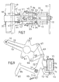
- the adjusting plungers 5, 6 with their drive mechanism and the electromagnets 16, 17 are held on the inner wall 15 shown in FIG. 7, while the housing inner wall 14 carrying the main shaft bearing 12 supports the pivot axis 18 (FIG. 9) of two pawls 19, 20 Pivot axis 21 of a release lever 22 for the pawls 19, 20 and a lock lever 23, a bearing axis 24 of gear wheels 25 of the drive system of the main machine shaft 1 and two electromagnets 26, 27 for the pivoting movement of the release lever 22 and the lock lever 23.
- each toothed rack has, in addition to the engagement toothing 28 which is in engagement with one of the pinions 3, a drive toothing 29 with tooth-shaped teeth 30 and a locking toothing 31 with a so-called castle toothing.
- the setting of a certain quantity of value on the stamps type wheels of the franking head 2 is carried out by gradually shifting the respective racks 4, 4 'by one tooth 30 by the pecking and pushing movement of the adjusting plungers 5, 6, as described in the above-mentioned US Pat. No. 4,520,725 is described.
- FIG. 7 only the electromagnets 16, 17 causing the pushing movement are shown, while the electromagnets for the tilting or engaging movement of the adjusting plungers 5, 6 are arranged below the electromagnets.
- a pair 5, 6 of the adjusting plungers are connected in an articulated manner by a bracket 32, at their ends
- the holes provided each enclose the pin 33, 34, which connects the armature 35, 36 of the electromagnet 16, 17 to the adjusting plunger 5, 6 in an articulated manner.
- the bracket 32 thus does not hinder the separate actuating movement of the adjusting plungers 5, 6.
- both electromagnets 16, 17 receive current simultaneously due to the control by a control unit of the franking machine, the bracket 32 moves in the direction of the main machine shaft 1 and thereby presses a bolt 37 fastened in its center into the v-shaped gap indicated by dashed lines between the shorter legs 38, 39 of two spreading legs 41, 42, which intersect like scissors on their hinge pin 40, so that they spread apart against the force of a spring 43 connecting them, out of engagement with the latching pawls 44, 45 provided for each toothed rack 4, 4 ' to spread the drive toothing 29.
- the setting position of the main shaft 1 is secured by the control wheel 49, so that the toothed racks with their drive toothing 29 are located exactly below the adjusting rams 5, 6.
- the control wheel 49 For this one presses at the end of a lever 50 mounted roller 51 in an indentation 52 on the circumference of the control wheel 49.
- the locking lever 23 engages with its hook part 53 in a recess 54 of the control wheel 49, so that rotation of the main machine shaft 1 or franking becomes possible only after an electromagnet 27 has pivoted the locking lever 23 back out of its locking position.
- the set franking value is added to the consumption memory of the franking machine.
- a backward rotation of the machine main shaft is prevented by the step 90 of the track 91 of the steering wheel 49 following the depression 54, on which the hook part 53 slides during the rotation of the machine main shaft 1.
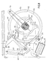
- a drive toothing 55 and a control track 56 are provided on the circumference of the steering wheel 49.
- a control roller 57 rolls on the control track 56, which controls the pressure movement of a pressure roller which presses a letter to be franked against the cliché with the type wheels.
- control groove 59 which, during the rotation of the main machine shaft 1, ensures the engagement of the pawls 18, 19 in a gap 60 of the locking teeth 31 of the racks 4, 4 '. by leading control pins 61, 62 provided on the pawls 18, 19.
- the control groove 59 has a radially outward extension 63, 64 in the area of the control bolts 61, 62. which run continuously into the otherwise circular control groove 59 in the circumferential direction.
- FIG. 1 An example of a suitable lever mechanism for locking and releasing the racks 4, 4 'by the pivoting movement of the pawls 18, 19 about their pivot axis 18 is shown in FIG.
- the outer ends of the pawls 19, 20 are each connected to an end 70 of a four-arm trigger lever 22 via a joint 66, 67 and one arm 68, 69.
- the lever arm 72, on which the electromagnet 26 acts, is provided at its end with a plate 73 which forms a hinged armature.
- a tie rod 74 of the electromagnet 26 reaches through an opening 75 of the flap core plate 73 and grips behind it, so that the electromagnet 26 acts both with a tie rod 74 and a flap armature and consequently a high holding force is available in relation to the electrical voltage to be applied.
- the winding 76 of the electromagnet 26 preferably encloses approximately half of its length an iron core 77 so that the tie rod 74 is pulled against this iron core 77.
- the electromagnet 26 has a magnetically acting iron jacket 78, on the end face 79 of which the hinged armature plate 73 comes to rest.
- one or more latches 44, 44 ', 45, 45' would sit on the tip of one of the teeth 30 of the drive toothing 29, ie be in an outwardly pivoted position (FIG. 6), so that their associated sensors 81, 82 signal the counter of the franking machine to a zero position of the rack or the associated value type wheel, because in the actual zero position, the latches 44, 44 ', 45, 45' are also in an outwardly pivoted position on the toothless part 83 of the rack 4 , 4 'as shown in Fig.1.
- the sensors 81, 82 consequently cannot distinguish between an incorrect position and a zero position of the toothed racks 4, 4 'or the latches. However, this is possible by means of the aforementioned sensor 80, which signals whether the toothed rack 4, 4 'is in a correct position.
- the senor 80 (FIG. 8) is actuated by a signal arm 84 of the release lever 22, in that the end 85 thereof extends into the switching range of e.g. Sensor 80 designed as a photo cell moves in when the pawls 19, 20 pivot outwards.
- each individual step-by-step actuating movement is preferably signaled or confirmed by the sensor 80 together with the sensors 81, 82 for the latching pawls to the control unit of the franking machine, so that the pawls 19, 20 move together with each actuating movement of the adjusting plunger 5, 6 open and close, in which the electromagnet 26 receives current with the same pulse sequence as the electromagnets 16, 17 for the setting of a number of a stamp type wheel. For the setting of the number "3", the relevant electromagnet 16 or 17 and the electromagnet 26 consequently receive three current pulses in succession.
- the respective engagement of the pawls 19, 20 also secures the rack adjustment carried out by an adjustment plunger 5, 6, so that the toothed racks 4, 4 'cannot be retracted into the zero position by their associated return spring 7 if the detent pawls 44, 44', 45, 45 'assigned to them jump out of their detent position in the drive toothing 29 due to strong vibration of the franking machine .
- the pawls 19, 20 also prevent the type wheels or the toothed racks from being manipulated on the franking head 2 from the outside.
- the release lever 22 for the pawls 19, 20 and the locking lever 23 engaging in the recess 54 on the circumference of the steering wheel 49 are through the the same tool is punched out as sheet metal parts, so that the release lever 22 completely covers the locking lever 23 in the illustration in FIG. 8.
- the electromagnets 26, 27 and the tension springs 65 engaging on these levers 22, 23 overlap.
- the locking lever 23 is changed relative to the release lever 22 by cutting away the lever end 70 along the broken line 86, since this would hinder its movement.
- the release lever 22 and the locking lever 23 partially cover the lever 50 which carries the roller 51 and which is pressed by the stronger spring 87 about the common pivot axis 21 against the steering wheel 49.
Landscapes
- Engineering & Computer Science (AREA)
- Computer Security & Cryptography (AREA)
- Physics & Mathematics (AREA)
- General Physics & Mathematics (AREA)
- Devices For Checking Fares Or Tickets At Control Points (AREA)
- Telephone Function (AREA)
- Data Exchanges In Wide-Area Networks (AREA)
- Computer And Data Communications (AREA)
- Iron Core Of Rotating Electric Machines (AREA)
- Lubrication Of Internal Combustion Engines (AREA)
- Holo Graphy (AREA)
Priority Applications (1)
| Application Number | Priority Date | Filing Date | Title |
|---|---|---|---|
| AT86115113T ATE49483T1 (de) | 1985-11-12 | 1986-10-31 | Frankiermaschine. |
Applications Claiming Priority (2)
| Application Number | Priority Date | Filing Date | Title |
|---|---|---|---|
| CH4841/85A CH669056A5 (de) | 1985-11-12 | 1985-11-12 | Frankiermaschine. |
| CH4841/85 | 1985-11-12 |
Publications (3)
| Publication Number | Publication Date |
|---|---|
| EP0222275A2 true EP0222275A2 (fr) | 1987-05-20 |
| EP0222275A3 EP0222275A3 (en) | 1988-06-01 |
| EP0222275B1 EP0222275B1 (fr) | 1990-01-10 |
Family
ID=4283490
Family Applications (1)
| Application Number | Title | Priority Date | Filing Date |
|---|---|---|---|
| EP86115113A Expired - Lifetime EP0222275B1 (fr) | 1985-11-12 | 1986-10-31 | Machine à affranchir |
Country Status (6)
| Country | Link |
|---|---|
| US (1) | US4898093A (fr) |
| EP (1) | EP0222275B1 (fr) |
| JP (1) | JPS62113585A (fr) |
| AT (1) | ATE49483T1 (fr) |
| CH (1) | CH669056A5 (fr) |
| DE (1) | DE3668246D1 (fr) |
Families Citing this family (4)
| Publication number | Priority date | Publication date | Assignee | Title |
|---|---|---|---|---|
| CH678366A5 (fr) * | 1989-03-08 | 1991-08-30 | Frama Ag | |
| CH678367A5 (fr) * | 1989-03-08 | 1991-08-30 | Frama Ag | |
| CH678368A5 (fr) * | 1989-03-29 | 1991-08-30 | Frama Ag | |
| FR2665781B1 (fr) * | 1990-08-07 | 1993-06-11 | Alcatel Satmam | Dispositif de verrouillage de molettes d'une machine a affranchir. |
Family Cites Families (12)
| Publication number | Priority date | Publication date | Assignee | Title |
|---|---|---|---|---|
| AT302421B (de) * | 1969-04-18 | 1972-10-10 | Itt Austria | Elektromagnetische Impulszähleinrichtung |
| US3682378A (en) * | 1970-11-23 | 1972-08-08 | Pitney Bowes Inc | Value dispensing mechanisms |
| US3731068A (en) * | 1970-11-23 | 1973-05-01 | Pitney Bowes Inc | Value dispensing mechanisms |
| US3890491A (en) * | 1974-04-03 | 1975-06-17 | A J M Res Corp | Arithmetic unit for a postage meter |
| US3916785A (en) * | 1974-06-03 | 1975-11-04 | Ncr Co | Imprinting means for a computer access terminal |
| US3965815A (en) * | 1974-09-16 | 1976-06-29 | Pitney-Bowes, Inc. | Setting mechanism for a postage printing device |
| US3949330A (en) * | 1974-12-23 | 1976-04-06 | Square D Company | Coil and trip mechanism |
| US3961298A (en) * | 1975-05-07 | 1976-06-01 | The Singer Company | Dual plunger solenoid |
| FR2354602A1 (fr) * | 1976-06-09 | 1978-01-06 | Secap | Dispositif automatique de mise a valeur des molettes d'impression dans une machine a affranchir |
| DE3111949C2 (de) * | 1981-03-23 | 1985-06-20 | Francotyp - Postalia GmbH, 1000 Berlin | Einstellvorrichtung für Frankier- und Wertstempelmaschinen |
| CH663848A5 (de) * | 1982-10-04 | 1988-01-15 | Frama Ag | Einstelleinrichtung fuer typenraeder. |
| GB8511170D0 (en) * | 1985-05-02 | 1985-06-12 | Pneupac Ltd | Resuscitator/ventilator |
-
1985
- 1985-11-12 CH CH4841/85A patent/CH669056A5/de not_active IP Right Cessation
-
1986
- 1986-10-15 JP JP61245176A patent/JPS62113585A/ja active Pending
- 1986-10-31 EP EP86115113A patent/EP0222275B1/fr not_active Expired - Lifetime
- 1986-10-31 AT AT86115113T patent/ATE49483T1/de active
- 1986-10-31 DE DE8686115113T patent/DE3668246D1/de not_active Expired - Lifetime
-
1988
- 1988-10-06 US US07/256,070 patent/US4898093A/en not_active Expired - Fee Related
Also Published As
| Publication number | Publication date |
|---|---|
| CH669056A5 (de) | 1989-02-15 |
| JPS62113585A (ja) | 1987-05-25 |
| ATE49483T1 (de) | 1990-01-15 |
| DE3668246D1 (de) | 1990-02-15 |
| EP0222275B1 (fr) | 1990-01-10 |
| EP0222275A3 (en) | 1988-06-01 |
| US4898093A (en) | 1990-02-06 |
Similar Documents
| Publication | Publication Date | Title |
|---|---|---|
| DE2538374C2 (de) | Einstellvorrichtung für ein Portodruckgerät | |
| DE68915373T2 (de) | Verriegelungsvorrichtung für die Tür einer Waschmaschine, einer Schleuder oder dergleichen. | |
| EP0105424A2 (fr) | Dispositif de sélection pour roues porte-caractère d'une imprimante | |
| DE2146765B2 (de) | Spritzgießform mit mehreren, schrittweise voneinander trennbaren Formplatten | |
| EP0758727A2 (fr) | Transmission hydrostatique pour un véhicule avec un levier de commande | |
| DE2430407C3 (de) | Mosaik-Drahtdruckkopf | |
| EP0374579B1 (fr) | Etiqueteuse manuelle | |
| DE2710044A1 (de) | Einrichtung fuer den fadenwechsel bei rundstrickmaschinen | |
| DE2833713A1 (de) | Elektronisch gesteuertes druckwerk | |
| DE69413779T2 (de) | Schablonendruckmaschine mit Mitteln zur transversalen Druckbildpositionseinstellung | |
| EP0222275B1 (fr) | Machine à affranchir | |
| DE3034836C2 (de) | Zeilenschaltvorrichtung für Schreib- o.ä. Maschinen | |
| DE19938378A1 (de) | Vorrichtung zum Öffnen und Verschließen einer Öffnung in einer Wandung mittels einer Schiebetür | |
| DE3003842A1 (de) | Vorrichtung zur werteinstellung, insbesondere bei frankiermaschinen | |
| DE3518419A1 (de) | Betaetigungsvorrichtung fuer einen schalter | |
| DE2364858C3 (de) | Mechanisches Steuerelement mit Speichermöglichkeit ausgewählter Einstellpositionen | |
| DE1698624B1 (de) | Zeigerwerksanordnung fuer elektrische Uhren | |
| DE3728672A1 (de) | Farbkastenvorrichtung fuer eine druckmaschine | |
| DE6610425U (de) | Typenhebelbewegungsvorrichtung mit kraftantrieb fuer schreibmaschinen. | |
| WO1992010418A1 (fr) | Dispositif pour l'alimentation en feuilles d'un systeme de transport ulterieur de feuilles d'un appareil | |
| DE3806026C1 (fr) | ||
| DE2826573C3 (de) | Kupplung für eine Vorrichtung zum Zuführen von Bahnmaterial in vorbestimmter Länge eines Kopiergeräts | |
| DE2925042C2 (de) | Vorrichtung zum mustergemäßen Kuppeln bzw. Entkuppeln der Klöppel einer Spitzenklöppelmaschine | |
| DE2948756A1 (de) | Einrichtung zur automatischen positionssteuerung eines maschinenteils | |
| DE2032250C3 (de) | Belegfördervorrichtung für Registrierkassen oder ähnliche datenverarbeitende Maschinen |
Legal Events
| Date | Code | Title | Description |
|---|---|---|---|
| PUAI | Public reference made under article 153(3) epc to a published international application that has entered the european phase |
Free format text: ORIGINAL CODE: 0009012 |
|
| AK | Designated contracting states |
Kind code of ref document: A2 Designated state(s): AT BE DE FR GB IT NL SE |
|
| PUAL | Search report despatched |
Free format text: ORIGINAL CODE: 0009013 |
|
| AK | Designated contracting states |
Kind code of ref document: A3 Designated state(s): AT BE DE FR GB IT NL SE |
|
| 17P | Request for examination filed |
Effective date: 19881102 |
|
| 17Q | First examination report despatched |
Effective date: 19890505 |
|
| GRAA | (expected) grant |
Free format text: ORIGINAL CODE: 0009210 |
|
| AK | Designated contracting states |
Kind code of ref document: B1 Designated state(s): AT BE DE FR GB IT NL SE |
|
| REF | Corresponds to: |
Ref document number: 49483 Country of ref document: AT Date of ref document: 19900115 Kind code of ref document: T |
|
| REF | Corresponds to: |
Ref document number: 3668246 Country of ref document: DE Date of ref document: 19900215 |
|
| ITF | It: translation for a ep patent filed | ||
| GBT | Gb: translation of ep patent filed (gb section 77(6)(a)/1977) | ||
| ET | Fr: translation filed | ||
| PLBI | Opposition filed |
Free format text: ORIGINAL CODE: 0009260 |
|
| 26 | Opposition filed |
Opponent name: FRANCOTYP- POSTALIA GMBH Effective date: 19901010 |
|
| NLR1 | Nl: opposition has been filed with the epo |
Opponent name: FRANCOTYPE- POSTALIA GMBH. |
|
| ITTA | It: last paid annual fee | ||
| PGFP | Annual fee paid to national office [announced via postgrant information from national office to epo] |
Ref country code: GB Payment date: 19920916 Year of fee payment: 7 Ref country code: DE Payment date: 19920916 Year of fee payment: 7 |
|
| PGFP | Annual fee paid to national office [announced via postgrant information from national office to epo] |
Ref country code: BE Payment date: 19920921 Year of fee payment: 7 |
|
| PGFP | Annual fee paid to national office [announced via postgrant information from national office to epo] |
Ref country code: AT Payment date: 19920922 Year of fee payment: 7 |
|
| PGFP | Annual fee paid to national office [announced via postgrant information from national office to epo] |
Ref country code: FR Payment date: 19920924 Year of fee payment: 7 |
|
| PGFP | Annual fee paid to national office [announced via postgrant information from national office to epo] |
Ref country code: SE Payment date: 19920928 Year of fee payment: 7 |
|
| PGFP | Annual fee paid to national office [announced via postgrant information from national office to epo] |
Ref country code: NL Payment date: 19921031 Year of fee payment: 7 |
|
| RDAG | Patent revoked |
Free format text: ORIGINAL CODE: 0009271 |
|
| STAA | Information on the status of an ep patent application or granted ep patent |
Free format text: STATUS: PATENT REVOKED |
|
| 27W | Patent revoked |
Effective date: 19921220 |
|
| GBPR | Gb: patent revoked under art. 102 of the ep convention designating the uk as contracting state |
Free format text: 921220 |
|
| NLR2 | Nl: decision of opposition | ||
| EUG | Se: european patent has lapsed |
Ref document number: 86115113.2 Effective date: 19930210 |
|
| APAH | Appeal reference modified |
Free format text: ORIGINAL CODE: EPIDOSCREFNO |
|
| PLAB | Opposition data, opponent's data or that of the opponent's representative modified |
Free format text: ORIGINAL CODE: 0009299OPPO |