EP0222284A2 - Procédé de montage de toits, murs, planchers et plafonds à isolation thermique - Google Patents
Procédé de montage de toits, murs, planchers et plafonds à isolation thermique Download PDFInfo
- Publication number
- EP0222284A2 EP0222284A2 EP86115176A EP86115176A EP0222284A2 EP 0222284 A2 EP0222284 A2 EP 0222284A2 EP 86115176 A EP86115176 A EP 86115176A EP 86115176 A EP86115176 A EP 86115176A EP 0222284 A2 EP0222284 A2 EP 0222284A2
- Authority
- EP
- European Patent Office
- Prior art keywords
- base
- holes
- roof
- insulating plates
- insulating
- Prior art date
- Legal status (The legal status is an assumption and is not a legal conclusion. Google has not performed a legal analysis and makes no representation as to the accuracy of the status listed.)
- Granted
Links
Images
Classifications
-
- E—FIXED CONSTRUCTIONS
- E04—BUILDING
- E04B—GENERAL BUILDING CONSTRUCTIONS; WALLS, e.g. PARTITIONS; ROOFS; FLOORS; CEILINGS; INSULATION OR OTHER PROTECTION OF BUILDINGS
- E04B1/00—Constructions in general; Structures which are not restricted either to walls, e.g. partitions, or floors or ceilings or roofs
- E04B1/38—Connections for building structures in general
- E04B1/41—Connecting devices specially adapted for embedding in concrete or masonry
-
- E—FIXED CONSTRUCTIONS
- E04—BUILDING
- E04B—GENERAL BUILDING CONSTRUCTIONS; WALLS, e.g. PARTITIONS; ROOFS; FLOORS; CEILINGS; INSULATION OR OTHER PROTECTION OF BUILDINGS
- E04B7/00—Roofs; Roof construction with regard to insulation
- E04B7/20—Roofs consisting of self-supporting slabs, e.g. able to be loaded
- E04B7/22—Roofs consisting of self-supporting slabs, e.g. able to be loaded the slabs having insulating properties, e.g. laminated with layers of insulating material
- E04B7/225—Roofs consisting of self-supporting slabs, e.g. able to be loaded the slabs having insulating properties, e.g. laminated with layers of insulating material the slabs having non-structural supports for roofing materials
-
- E—FIXED CONSTRUCTIONS
- E04—BUILDING
- E04D—ROOF COVERINGS; SKY-LIGHTS; GUTTERS; ROOF-WORKING TOOLS
- E04D13/00—Special arrangements or devices in connection with roof coverings; Protection against birds; Roof drainage ; Sky-lights
- E04D13/16—Insulating devices or arrangements in so far as the roof covering is concerned, e.g. characterised by the material or composition of the roof insulating material or its integration in the roof structure
- E04D13/1606—Insulation of the roof covering characterised by its integration in the roof structure
- E04D13/1612—Insulation of the roof covering characterised by its integration in the roof structure the roof structure comprising a supporting framework of roof purlins or rafters
- E04D13/1618—Insulation of the roof covering characterised by its integration in the roof structure the roof structure comprising a supporting framework of roof purlins or rafters with means for fixing the insulating material between the roof covering and the upper surface of the roof purlins or rafters
-
- E—FIXED CONSTRUCTIONS
- E04—BUILDING
- E04B—GENERAL BUILDING CONSTRUCTIONS; WALLS, e.g. PARTITIONS; ROOFS; FLOORS; CEILINGS; INSULATION OR OTHER PROTECTION OF BUILDINGS
- E04B1/00—Constructions in general; Structures which are not restricted either to walls, e.g. partitions, or floors or ceilings or roofs
- E04B1/38—Connections for building structures in general
- E04B2001/386—Nailable or screwable inserts for foam panels
Definitions
- the invention relates to a method for assembling thermally insulated roofs, walls, floors and ceilings, a roof, a wall, a floor or a ceiling with thermal insulation, a support body for insulating plates between a base and a cover and a drill for drilling such Supporting holes in heat-insulating plates.
- the invention seeks to remedy this.
- the invention as characterized in claim 1, solves the problem of reliably achieving a seamless and thus effective thermal insulation in a simple and time-saving manner.
- This is essentially achieved according to the invention in that the insulating plates, for example in the case of a roof on a formwork supported on the rafters directly adjacent to one another, are laid seamlessly, and that in adapted holes in the plates are seated supporting bodies connected to the rafters Hold the panels firmly against the formwork and wear the outer skin.
- the advantages achieved by the invention can essentially be seen in the fact that the plates are effortlessly joined together, i.e. can be easily butted against one another and that the supporting bodies not only support the panels but also the outer cover, e.g. on the load-bearing rafters. Overall, the invention is characterized in that reliable insulation is achieved in a simple, time-saving manner.
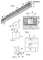
- a formwork 1 To assemble the roof shown, boards are nailed onto the rafters 2 to form a formwork 1.
- the formwork 1 is covered with a vapor barrier 4 (FIG. 2), for example from overlapping, glued plastic sheets or by means of a flame, welded roofing felt sheets, and a layer of immediately, seamlessly and closely abutting insulating plates 6, for example made of foam plastic, is placed thereon is supported on the eaves of the roof on a beam 8 to which the gutter (not shown) is attached.
- a vapor barrier 4 for example from overlapping, glued plastic sheets or by means of a flame, welded roofing felt sheets, and a layer of immediately, seamlessly and closely abutting insulating plates 6, for example made of foam plastic, is placed thereon is supported on the eaves of the roof on a beam 8 to which the gutter (not shown) is attached.
- the format and the size of the insulating plates 6 can be freely selected.
- holes 10 are drilled at locations lying above the rafters 2, the spacing along the rafters 2 depending on the roof pitch and snow load to be taken into account, for example 60-120 cm can be. It is not necessary to provide each insulating plate 6 with a hole 10. These holes serve to accommodate them adapted support body 12, which are described in more detail below in connection with FIGS. 3 and 4, and can expediently with a special, further Drill 14 also described in more detail below in connection with FIG. 5.
- the holes 10 are cylindrical blind holes which extend up to a few millimeters to the lower side of the plates 6, so that a thin hole bottom 16 remains there (FIG. 2).
- the support bodies 12 are inserted into the holes 10 and individually connected to the rafters 2 by a connecting means which is passed through a through hole 18 of the support body 12 and engages through the perforated base 16, the vapor barrier 4 and the formwork 1 in the rafters 2 .
- the lanyard can be a nail or a wood screw.
- These connecting means are suitable for penetrating the perforated base 16, if the plates 6 are made of foam plastic, for example, as well as the vapor barrier 4 and the formwork 1 itself and penetrating the rafters 2 themselves and firmly adhering to them.
- the perforated base 16 and the vapor barrier 4 are pressed together between the supporting body 12 and the formwork 1, the vapor barrier 4 remains vapor-tight despite the hole caused by the connecting means.
- the perforated base 16 could also be removed after the hole 10 had been drilled, ie the insulating plate material forming it could be removed, so that the support body is then pressed directly onto the vapor barrier 4.
- a so-called sub-roof 20 (FIG. 2), which can be designed in the same way as the vapor barrier 4, is placed over the layer of insulating plates 6, which is supported in a shear-resistant manner, and on top of this a flat piece is placed at each point above a supporting body 12 self-adhesive seal material existing seal 21 attached.
- a counter batten 22 is placed on the roof 20 above each roof rafter 2 placed and connected to the support bodies 12 by nails 23 (Fig. 2) or screws, the seals 21 compressed between the counter battens 22 and the sub-roof 20 sealing the penetration points of the nails 23 or screws.
- roof battens 23 can be nailed onto the counter battens as carriers for the roof tiles.
- each insulating plate 6 is installed during installation, e.g. with nails, dowels, e.g. Plastic dowels or an adhesive, so firmly connected to the base that they are adequately fixed when drilling the holes 10, inserting the support body 12 and connecting them to the base and until an outer skin is attached.
- dowels e.g. Plastic dowels or an adhesive
- the supporting bodies 12 can be made of wood, but a non-rotting, sufficiently strong material is expedient, which is suitable for holding a nail or a wood screw in a tensile manner without first having to drill a hole for it.
- Materials of this type are preferably filler-binder mixtures.
- a suitable material consists, for example, of a mixture of 23% by weight synthetic resin (trade name Grilonit GV 31.1520), 9% by weight hardener (Trade name Grilonit V 48-15) and 68 wt .-% filler, which is pressed into a cylindrical shape, pre-hardened, removed from the mold and hardened.
- a filling material made of very small hollow spheres made of A1 2 0 3 , Si0 2 and Fe 2 0 3 with the trade name Fillite, type 52/7 is suitable as filling material.
- the hole 18 can be central or eccentric in the support body 12.
- each support body 12 in the case of a sloping roof or a wall, each support body 12 is to be inserted into its hole 10 in such a way that the hole 18 lies vertically above the axis of the support body 12. Otherwise, the thrust that the insulating plates 6 exert due to their weight on the supporting body 12 could cause the latter to rotate and thus cause a displacement of the insulating plates 6, whereupon their immediate close abutment would no longer be guaranteed.
- the drill 14 is basically a cylinder head drill, it differs from the usual drills of this type in that its shaft 32 does not have a pin with a centering tip, but rather a cap screw (in the example with a hexagon head 34) is screwed into the shaft 32, so that her head 34 forms a stop projecting beyond the cutting edges 36 and end cutting edges 38.
- a stop could also be formed in a different way and in another suitable form.
- this stop 34 can penetrate without further ado until it abuts or almost touches the vapor barrier 4, which is supported by the non-yielding formwork 1, which at the points where the holes 10 are drilled, is supported by the rafters 2.
- the drill 14 can be used with a conventional, hands-free, electric hand drill. More expedient, however, is a boring frame to be placed on the insulating plates 6, in which the drive device for the drill 14 is axially displaceably mounted and can be advanced against a spring force.
Landscapes
- Engineering & Computer Science (AREA)
- Architecture (AREA)
- Civil Engineering (AREA)
- Structural Engineering (AREA)
- Physics & Mathematics (AREA)
- Electromagnetism (AREA)
- Building Environments (AREA)
- Joining Of Building Structures In Genera (AREA)
Priority Applications (1)
| Application Number | Priority Date | Filing Date | Title |
|---|---|---|---|
| AT86115176T ATE78544T1 (de) | 1985-11-06 | 1986-11-01 | Verfahren zur montage waermeisolierter daecher, waende, boeden und decken. |
Applications Claiming Priority (2)
| Application Number | Priority Date | Filing Date | Title |
|---|---|---|---|
| CH475485 | 1985-11-06 | ||
| CH4754/85 | 1985-11-06 |
Publications (3)
| Publication Number | Publication Date |
|---|---|
| EP0222284A2 true EP0222284A2 (fr) | 1987-05-20 |
| EP0222284A3 EP0222284A3 (en) | 1987-09-30 |
| EP0222284B1 EP0222284B1 (fr) | 1992-07-22 |
Family
ID=4281926
Family Applications (1)
| Application Number | Title | Priority Date | Filing Date |
|---|---|---|---|
| EP86115176A Expired - Lifetime EP0222284B1 (fr) | 1985-11-06 | 1986-11-01 | Procédé de montage de toits, murs, planchers et plafonds à isolation thermique |
Country Status (3)
| Country | Link |
|---|---|
| EP (1) | EP0222284B1 (fr) |
| AT (1) | ATE78544T1 (fr) |
| DE (1) | DE3686128D1 (fr) |
Cited By (7)
| Publication number | Priority date | Publication date | Assignee | Title |
|---|---|---|---|---|
| EP0424690A1 (fr) * | 1989-10-23 | 1991-05-02 | Geberit AG | Bloc d'installation en mousse pour locaux sanitaires |
| WO1991007553A1 (fr) * | 1989-11-13 | 1991-05-30 | Mario Flepp | Procede pour la fixation d'elements sur une isolation exterieure et support de montage pour la mise en ×uvre du procede |
| WO1991010021A1 (fr) * | 1989-12-22 | 1991-07-11 | Mario Flepp | Procede pour la fixation d'elements et support de montage pour la realisation du procede |
| EP0877127A1 (fr) * | 1997-05-09 | 1998-11-11 | Reinhard Casutt | Procédé de réalisation d'une liaison entre la couverture et la charpente d'une toiture à travers un isolant thermique, trépan et outillage relatif, et toiture isolée |
| NL1009801C2 (nl) | 1998-08-05 | 2000-02-08 | Exploitatiemaatschappij Merode | Werkwijze ter vervaardiging van een isolatie-element, een volgens een dergelijke werkwijze verkregen isolatie-element, alsmede een dakconstructie voorzien van één of meer dergelijke isolatie-elementen. |
| EP0978601A1 (fr) | 1998-08-05 | 2000-02-09 | Exploitatiemaatschappij Merode B.V. | Procédé et dispositif de fabrication d'un élément isolant et élément ainsi obtenu |
| EP2105548A1 (fr) * | 2008-03-26 | 2009-09-30 | Wood Beton S.p.A. | Panneau de couverture pour toit, structure de charpente et son procédé de mise en place |
Family Cites Families (3)
| Publication number | Priority date | Publication date | Assignee | Title |
|---|---|---|---|---|
| NL6802922A (fr) * | 1968-03-01 | 1969-09-03 | ||
| DE2237091A1 (de) * | 1972-07-28 | 1974-02-14 | Fritz Klaus Fischer | Dach, insbesondere flachdach |
| NO793519L (no) * | 1979-11-01 | 1981-05-05 | Protan & Fagertun As | Fremgangsmaate ved festing av isolerende og tettende sjikt samt anordning for utfoerelse av fremgangsmaaten |
-
1986
- 1986-11-01 DE DE8686115176T patent/DE3686128D1/de not_active Expired - Lifetime
- 1986-11-01 AT AT86115176T patent/ATE78544T1/de not_active IP Right Cessation
- 1986-11-01 EP EP86115176A patent/EP0222284B1/fr not_active Expired - Lifetime
Cited By (7)
| Publication number | Priority date | Publication date | Assignee | Title |
|---|---|---|---|---|
| EP0424690A1 (fr) * | 1989-10-23 | 1991-05-02 | Geberit AG | Bloc d'installation en mousse pour locaux sanitaires |
| WO1991007553A1 (fr) * | 1989-11-13 | 1991-05-30 | Mario Flepp | Procede pour la fixation d'elements sur une isolation exterieure et support de montage pour la mise en ×uvre du procede |
| WO1991010021A1 (fr) * | 1989-12-22 | 1991-07-11 | Mario Flepp | Procede pour la fixation d'elements et support de montage pour la realisation du procede |
| EP0877127A1 (fr) * | 1997-05-09 | 1998-11-11 | Reinhard Casutt | Procédé de réalisation d'une liaison entre la couverture et la charpente d'une toiture à travers un isolant thermique, trépan et outillage relatif, et toiture isolée |
| NL1009801C2 (nl) | 1998-08-05 | 2000-02-08 | Exploitatiemaatschappij Merode | Werkwijze ter vervaardiging van een isolatie-element, een volgens een dergelijke werkwijze verkregen isolatie-element, alsmede een dakconstructie voorzien van één of meer dergelijke isolatie-elementen. |
| EP0978601A1 (fr) | 1998-08-05 | 2000-02-09 | Exploitatiemaatschappij Merode B.V. | Procédé et dispositif de fabrication d'un élément isolant et élément ainsi obtenu |
| EP2105548A1 (fr) * | 2008-03-26 | 2009-09-30 | Wood Beton S.p.A. | Panneau de couverture pour toit, structure de charpente et son procédé de mise en place |
Also Published As
| Publication number | Publication date |
|---|---|
| DE3686128D1 (de) | 1992-08-27 |
| EP0222284B1 (fr) | 1992-07-22 |
| ATE78544T1 (de) | 1992-08-15 |
| EP0222284A3 (en) | 1987-09-30 |
Similar Documents
| Publication | Publication Date | Title |
|---|---|---|
| DE69517971T2 (de) | Nagel zum befestigen von plattenförmigem material | |
| EP0921252A2 (fr) | Elément de fixation pour la fixation à distance de lattes, profilés, panneaux ou similaires sur un support fix, guide de perçage pour trous dans un fond, pour l'insertion d'éléments de fixation et procédé pour la fixation à distance à l'aide d'un tel élément de fixation | |
| EP2715156B1 (fr) | Système de fixation d'une façade isolante et dispositif de fixation prévu à cet effet | |
| EP0222284B1 (fr) | Procédé de montage de toits, murs, planchers et plafonds à isolation thermique | |
| EP0854252B1 (fr) | Couverture de bâtiment | |
| DE202019001906U1 (de) | Einschraubdübel | |
| CH674545A5 (en) | Skylight-installation equipment - comprises hollow top and bottom frames fitting together and containing insulating material | |
| EP2184418B1 (fr) | Montage d'un module photovoltaic dans une toiture | |
| EP0517667B1 (fr) | Elément d'appui | |
| EP1799926B1 (fr) | Toit de batiment, structure a couche d'isolation et element d'isolation a fibres minerales destine a un toit de batiment | |
| DE102021003062B4 (de) | Ankernagel für Faserwolle-Dämmmatten | |
| EP1045945A1 (fr) | Element support pour fixer des substructures | |
| AT525083B1 (de) | Bausatz für einen Attikaaufbau an einem Gebäude | |
| CH702527A2 (de) | Dach-Unterkonstruktion. | |
| DE29604846U1 (de) | Dachkonstruktion | |
| EP2331767B1 (fr) | Elément de fixation modulaire et outil de vissage dudit élément de fixation | |
| DE4101133C2 (de) | Verfahren zur Befestigung von Bahnen an Holzwolle-Leichtbauplatten | |
| DE4405748A1 (de) | Verbundplatte, insbesondere zum Dachinnenausbau | |
| DE19923545A1 (de) | Verfahren zur Abdichtung eines Daches bzw. Verkleidung einer Wand mit Unterkonstruktion | |
| DE102024116928A1 (de) | Befestigungssystem für Bauteile an einem tragenden Untergrund | |
| DE3817238A1 (de) | Waermedaemmplatte | |
| EP1319769B1 (fr) | Panneau isolant pour toiture | |
| EP1288388A1 (fr) | Profile intercalaire et construction associee de toit ou paroi | |
| EP2857610A1 (fr) | Elément d'isolation, enveloppe de bâtiment et procédé d'isolation | |
| DE2551706A1 (de) | Bauteil zur befestigung beluefteter wandverkleidungen |
Legal Events
| Date | Code | Title | Description |
|---|---|---|---|
| PUAI | Public reference made under article 153(3) epc to a published international application that has entered the european phase |
Free format text: ORIGINAL CODE: 0009012 |
|
| AK | Designated contracting states |
Kind code of ref document: A2 Designated state(s): AT CH DE FR IT LI SE |
|
| PUAL | Search report despatched |
Free format text: ORIGINAL CODE: 0009013 |
|
| AK | Designated contracting states |
Kind code of ref document: A3 Designated state(s): AT CH DE FR IT LI SE |
|
| 17P | Request for examination filed |
Effective date: 19880303 |
|
| 17Q | First examination report despatched |
Effective date: 19890224 |
|
| GRAA | (expected) grant |
Free format text: ORIGINAL CODE: 0009210 |
|
| AK | Designated contracting states |
Kind code of ref document: B1 Designated state(s): AT CH DE FR IT LI SE |
|
| REF | Corresponds to: |
Ref document number: 78544 Country of ref document: AT Date of ref document: 19920815 Kind code of ref document: T |
|
| ITF | It: translation for a ep patent filed | ||
| ET | Fr: translation filed | ||
| REF | Corresponds to: |
Ref document number: 3686128 Country of ref document: DE Date of ref document: 19920827 |
|
| PLBE | No opposition filed within time limit |
Free format text: ORIGINAL CODE: 0009261 |
|
| STAA | Information on the status of an ep patent application or granted ep patent |
Free format text: STATUS: NO OPPOSITION FILED WITHIN TIME LIMIT |
|
| 26N | No opposition filed | ||
| PGFP | Annual fee paid to national office [announced via postgrant information from national office to epo] |
Ref country code: FR Payment date: 19931123 Year of fee payment: 8 |
|
| PGFP | Annual fee paid to national office [announced via postgrant information from national office to epo] |
Ref country code: AT Payment date: 19931217 Year of fee payment: 8 |
|
| PG25 | Lapsed in a contracting state [announced via postgrant information from national office to epo] |
Ref country code: AT Effective date: 19941101 |
|
| EAL | Se: european patent in force in sweden |
Ref document number: 86115176.9 |
|
| PG25 | Lapsed in a contracting state [announced via postgrant information from national office to epo] |
Ref country code: FR Effective date: 19950731 |
|
| REG | Reference to a national code |
Ref country code: FR Ref legal event code: ST |
|
| PGFP | Annual fee paid to national office [announced via postgrant information from national office to epo] |
Ref country code: SE Payment date: 19951222 Year of fee payment: 10 |
|
| PGFP | Annual fee paid to national office [announced via postgrant information from national office to epo] |
Ref country code: DE Payment date: 19960108 Year of fee payment: 10 |
|
| PG25 | Lapsed in a contracting state [announced via postgrant information from national office to epo] |
Ref country code: SE Effective date: 19961102 |
|
| PG25 | Lapsed in a contracting state [announced via postgrant information from national office to epo] |
Ref country code: DE Effective date: 19970801 |
|
| EUG | Se: european patent has lapsed |
Ref document number: 86115176.9 |
|
| PGFP | Annual fee paid to national office [announced via postgrant information from national office to epo] |
Ref country code: CH Payment date: 19981228 Year of fee payment: 13 |
|
| PG25 | Lapsed in a contracting state [announced via postgrant information from national office to epo] |
Ref country code: LI Free format text: LAPSE BECAUSE OF NON-PAYMENT OF DUE FEES Effective date: 19991130 Ref country code: CH Free format text: LAPSE BECAUSE OF NON-PAYMENT OF DUE FEES Effective date: 19991130 |
|
| REG | Reference to a national code |
Ref country code: CH Ref legal event code: PL |
|
| PG25 | Lapsed in a contracting state [announced via postgrant information from national office to epo] |
Ref country code: IT Free format text: LAPSE BECAUSE OF NON-PAYMENT OF DUE FEES Effective date: 20051101 |