EP0222287B1 - Raccord ou manchon soudable électriquement - Google Patents
Raccord ou manchon soudable électriquement Download PDFInfo
- Publication number
- EP0222287B1 EP0222287B1 EP86115185A EP86115185A EP0222287B1 EP 0222287 B1 EP0222287 B1 EP 0222287B1 EP 86115185 A EP86115185 A EP 86115185A EP 86115185 A EP86115185 A EP 86115185A EP 0222287 B1 EP0222287 B1 EP 0222287B1
- Authority
- EP
- European Patent Office
- Prior art keywords
- electroweld
- reinforcement
- fitting according
- welding
- tube
- Prior art date
- Legal status (The legal status is an assumption and is not a legal conclusion. Google has not performed a legal analysis and makes no representation as to the accuracy of the status listed.)
- Expired - Lifetime
Links
Images

Classifications
-
- B—PERFORMING OPERATIONS; TRANSPORTING
- B29—WORKING OF PLASTICS; WORKING OF SUBSTANCES IN A PLASTIC STATE IN GENERAL
- B29C—SHAPING OR JOINING OF PLASTICS; SHAPING OF MATERIAL IN A PLASTIC STATE, NOT OTHERWISE PROVIDED FOR; AFTER-TREATMENT OF THE SHAPED PRODUCTS, e.g. REPAIRING
- B29C65/00—Joining or sealing of preformed parts, e.g. welding of plastics materials; Apparatus therefor
- B29C65/02—Joining or sealing of preformed parts, e.g. welding of plastics materials; Apparatus therefor by heating, with or without pressure
- B29C65/34—Joining or sealing of preformed parts, e.g. welding of plastics materials; Apparatus therefor by heating, with or without pressure using heated elements which remain in the joint, e.g. "verlorenes Schweisselement"
- B29C65/3404—Joining or sealing of preformed parts, e.g. welding of plastics materials; Apparatus therefor by heating, with or without pressure using heated elements which remain in the joint, e.g. "verlorenes Schweisselement" characterised by the type of heated elements which remain in the joint
- B29C65/342—Joining or sealing of preformed parts, e.g. welding of plastics materials; Apparatus therefor by heating, with or without pressure using heated elements which remain in the joint, e.g. "verlorenes Schweisselement" characterised by the type of heated elements which remain in the joint comprising at least a single wire, e.g. in the form of a winding
-
- B—PERFORMING OPERATIONS; TRANSPORTING
- B29—WORKING OF PLASTICS; WORKING OF SUBSTANCES IN A PLASTIC STATE IN GENERAL
- B29C—SHAPING OR JOINING OF PLASTICS; SHAPING OF MATERIAL IN A PLASTIC STATE, NOT OTHERWISE PROVIDED FOR; AFTER-TREATMENT OF THE SHAPED PRODUCTS, e.g. REPAIRING
- B29C65/00—Joining or sealing of preformed parts, e.g. welding of plastics materials; Apparatus therefor
- B29C65/02—Joining or sealing of preformed parts, e.g. welding of plastics materials; Apparatus therefor by heating, with or without pressure
- B29C65/34—Joining or sealing of preformed parts, e.g. welding of plastics materials; Apparatus therefor by heating, with or without pressure using heated elements which remain in the joint, e.g. "verlorenes Schweisselement"
- B29C65/3468—Joining or sealing of preformed parts, e.g. welding of plastics materials; Apparatus therefor by heating, with or without pressure using heated elements which remain in the joint, e.g. "verlorenes Schweisselement" characterised by the means for supplying heat to said heated elements which remain in the join, e.g. special electrical connectors of windings
-
- B—PERFORMING OPERATIONS; TRANSPORTING
- B29—WORKING OF PLASTICS; WORKING OF SUBSTANCES IN A PLASTIC STATE IN GENERAL
- B29C—SHAPING OR JOINING OF PLASTICS; SHAPING OF MATERIAL IN A PLASTIC STATE, NOT OTHERWISE PROVIDED FOR; AFTER-TREATMENT OF THE SHAPED PRODUCTS, e.g. REPAIRING
- B29C65/00—Joining or sealing of preformed parts, e.g. welding of plastics materials; Apparatus therefor
- B29C65/02—Joining or sealing of preformed parts, e.g. welding of plastics materials; Apparatus therefor by heating, with or without pressure
- B29C65/34—Joining or sealing of preformed parts, e.g. welding of plastics materials; Apparatus therefor by heating, with or without pressure using heated elements which remain in the joint, e.g. "verlorenes Schweisselement"
- B29C65/3472—Joining or sealing of preformed parts, e.g. welding of plastics materials; Apparatus therefor by heating, with or without pressure using heated elements which remain in the joint, e.g. "verlorenes Schweisselement" characterised by the composition of the heated elements which remain in the joint
- B29C65/3476—Joining or sealing of preformed parts, e.g. welding of plastics materials; Apparatus therefor by heating, with or without pressure using heated elements which remain in the joint, e.g. "verlorenes Schweisselement" characterised by the composition of the heated elements which remain in the joint being metallic
-
- B—PERFORMING OPERATIONS; TRANSPORTING
- B29—WORKING OF PLASTICS; WORKING OF SUBSTANCES IN A PLASTIC STATE IN GENERAL
- B29C—SHAPING OR JOINING OF PLASTICS; SHAPING OF MATERIAL IN A PLASTIC STATE, NOT OTHERWISE PROVIDED FOR; AFTER-TREATMENT OF THE SHAPED PRODUCTS, e.g. REPAIRING
- B29C66/00—General aspects of processes or apparatus for joining preformed parts
- B29C66/01—General aspects dealing with the joint area or with the area to be joined
- B29C66/05—Particular design of joint configurations
- B29C66/10—Particular design of joint configurations particular design of the joint cross-sections
- B29C66/11—Joint cross-sections comprising a single joint-segment, i.e. one of the parts to be joined comprising a single joint-segment in the joint cross-section
- B29C66/112—Single lapped joints
- B29C66/1122—Single lap to lap joints, i.e. overlap joints
-
- B—PERFORMING OPERATIONS; TRANSPORTING
- B29—WORKING OF PLASTICS; WORKING OF SUBSTANCES IN A PLASTIC STATE IN GENERAL
- B29C—SHAPING OR JOINING OF PLASTICS; SHAPING OF MATERIAL IN A PLASTIC STATE, NOT OTHERWISE PROVIDED FOR; AFTER-TREATMENT OF THE SHAPED PRODUCTS, e.g. REPAIRING
- B29C66/00—General aspects of processes or apparatus for joining preformed parts
- B29C66/50—General aspects of joining tubular articles; General aspects of joining long products, i.e. bars or profiled elements; General aspects of joining single elements to tubular articles, hollow articles or bars; General aspects of joining several hollow-preforms to form hollow or tubular articles
- B29C66/51—Joining tubular articles, profiled elements or bars; Joining single elements to tubular articles, hollow articles or bars; Joining several hollow-preforms to form hollow or tubular articles
- B29C66/52—Joining tubular articles, bars or profiled elements
- B29C66/522—Joining tubular articles
- B29C66/5221—Joining tubular articles for forming coaxial connections, i.e. the tubular articles to be joined forming a zero angle relative to each other
-
- B—PERFORMING OPERATIONS; TRANSPORTING
- B29—WORKING OF PLASTICS; WORKING OF SUBSTANCES IN A PLASTIC STATE IN GENERAL
- B29C—SHAPING OR JOINING OF PLASTICS; SHAPING OF MATERIAL IN A PLASTIC STATE, NOT OTHERWISE PROVIDED FOR; AFTER-TREATMENT OF THE SHAPED PRODUCTS, e.g. REPAIRING
- B29C66/00—General aspects of processes or apparatus for joining preformed parts
- B29C66/50—General aspects of joining tubular articles; General aspects of joining long products, i.e. bars or profiled elements; General aspects of joining single elements to tubular articles, hollow articles or bars; General aspects of joining several hollow-preforms to form hollow or tubular articles
- B29C66/51—Joining tubular articles, profiled elements or bars; Joining single elements to tubular articles, hollow articles or bars; Joining several hollow-preforms to form hollow or tubular articles
- B29C66/52—Joining tubular articles, bars or profiled elements
- B29C66/522—Joining tubular articles
- B29C66/5229—Joining tubular articles involving the use of a socket
-
- B—PERFORMING OPERATIONS; TRANSPORTING
- B29—WORKING OF PLASTICS; WORKING OF SUBSTANCES IN A PLASTIC STATE IN GENERAL
- B29C—SHAPING OR JOINING OF PLASTICS; SHAPING OF MATERIAL IN A PLASTIC STATE, NOT OTHERWISE PROVIDED FOR; AFTER-TREATMENT OF THE SHAPED PRODUCTS, e.g. REPAIRING
- B29C66/00—General aspects of processes or apparatus for joining preformed parts
- B29C66/50—General aspects of joining tubular articles; General aspects of joining long products, i.e. bars or profiled elements; General aspects of joining single elements to tubular articles, hollow articles or bars; General aspects of joining several hollow-preforms to form hollow or tubular articles
- B29C66/51—Joining tubular articles, profiled elements or bars; Joining single elements to tubular articles, hollow articles or bars; Joining several hollow-preforms to form hollow or tubular articles
- B29C66/52—Joining tubular articles, bars or profiled elements
- B29C66/522—Joining tubular articles
- B29C66/5229—Joining tubular articles involving the use of a socket
- B29C66/52295—Joining tubular articles involving the use of a socket said socket comprising reinforcements
-
- B—PERFORMING OPERATIONS; TRANSPORTING
- B29—WORKING OF PLASTICS; WORKING OF SUBSTANCES IN A PLASTIC STATE IN GENERAL
- B29C—SHAPING OR JOINING OF PLASTICS; SHAPING OF MATERIAL IN A PLASTIC STATE, NOT OTHERWISE PROVIDED FOR; AFTER-TREATMENT OF THE SHAPED PRODUCTS, e.g. REPAIRING
- B29C66/00—General aspects of processes or apparatus for joining preformed parts
- B29C66/70—General aspects of processes or apparatus for joining preformed parts characterised by the composition, physical properties or the structure of the material of the parts to be joined; Joining with non-plastics material
- B29C66/73—General aspects of processes or apparatus for joining preformed parts characterised by the composition, physical properties or the structure of the material of the parts to be joined; Joining with non-plastics material characterised by the intensive physical properties of the material of the parts to be joined, by the optical properties of the material of the parts to be joined, by the extensive physical properties of the parts to be joined, by the state of the material of the parts to be joined or by the material of the parts to be joined being a thermoplastic or a thermoset
- B29C66/739—General aspects of processes or apparatus for joining preformed parts characterised by the composition, physical properties or the structure of the material of the parts to be joined; Joining with non-plastics material characterised by the intensive physical properties of the material of the parts to be joined, by the optical properties of the material of the parts to be joined, by the extensive physical properties of the parts to be joined, by the state of the material of the parts to be joined or by the material of the parts to be joined being a thermoplastic or a thermoset characterised by the material of the parts to be joined being a thermoplastic or a thermoset
- B29C66/7392—General aspects of processes or apparatus for joining preformed parts characterised by the composition, physical properties or the structure of the material of the parts to be joined; Joining with non-plastics material characterised by the intensive physical properties of the material of the parts to be joined, by the optical properties of the material of the parts to be joined, by the extensive physical properties of the parts to be joined, by the state of the material of the parts to be joined or by the material of the parts to be joined being a thermoplastic or a thermoset characterised by the material of the parts to be joined being a thermoplastic or a thermoset characterised by the material of at least one of the parts being a thermoplastic
-
- B—PERFORMING OPERATIONS; TRANSPORTING
- B29—WORKING OF PLASTICS; WORKING OF SUBSTANCES IN A PLASTIC STATE IN GENERAL
- B29C—SHAPING OR JOINING OF PLASTICS; SHAPING OF MATERIAL IN A PLASTIC STATE, NOT OTHERWISE PROVIDED FOR; AFTER-TREATMENT OF THE SHAPED PRODUCTS, e.g. REPAIRING
- B29C66/00—General aspects of processes or apparatus for joining preformed parts
- B29C66/80—General aspects of machine operations or constructions and parts thereof
- B29C66/81—General aspects of the pressing elements, i.e. the elements applying pressure on the parts to be joined in the area to be joined, e.g. the welding jaws or clamps
-
- F—MECHANICAL ENGINEERING; LIGHTING; HEATING; WEAPONS; BLASTING
- F16—ENGINEERING ELEMENTS AND UNITS; GENERAL MEASURES FOR PRODUCING AND MAINTAINING EFFECTIVE FUNCTIONING OF MACHINES OR INSTALLATIONS; THERMAL INSULATION IN GENERAL
- F16L—PIPES; JOINTS OR FITTINGS FOR PIPES; SUPPORTS FOR PIPES, CABLES OR PROTECTIVE TUBING; MEANS FOR THERMAL INSULATION IN GENERAL
- F16L47/00—Connecting arrangements or other fittings specially adapted to be made of plastics or to be used with pipes made of plastics
- F16L47/02—Welded joints; Adhesive joints
- F16L47/03—Welded joints with an electrical resistance incorporated in the joint
-
- B—PERFORMING OPERATIONS; TRANSPORTING
- B29—WORKING OF PLASTICS; WORKING OF SUBSTANCES IN A PLASTIC STATE IN GENERAL
- B29C—SHAPING OR JOINING OF PLASTICS; SHAPING OF MATERIAL IN A PLASTIC STATE, NOT OTHERWISE PROVIDED FOR; AFTER-TREATMENT OF THE SHAPED PRODUCTS, e.g. REPAIRING
- B29C66/00—General aspects of processes or apparatus for joining preformed parts
- B29C66/70—General aspects of processes or apparatus for joining preformed parts characterised by the composition, physical properties or the structure of the material of the parts to be joined; Joining with non-plastics material
- B29C66/71—General aspects of processes or apparatus for joining preformed parts characterised by the composition, physical properties or the structure of the material of the parts to be joined; Joining with non-plastics material characterised by the composition of the plastics material of the parts to be joined
-
- B—PERFORMING OPERATIONS; TRANSPORTING
- B29—WORKING OF PLASTICS; WORKING OF SUBSTANCES IN A PLASTIC STATE IN GENERAL
- B29C—SHAPING OR JOINING OF PLASTICS; SHAPING OF MATERIAL IN A PLASTIC STATE, NOT OTHERWISE PROVIDED FOR; AFTER-TREATMENT OF THE SHAPED PRODUCTS, e.g. REPAIRING
- B29C66/00—General aspects of processes or apparatus for joining preformed parts
- B29C66/70—General aspects of processes or apparatus for joining preformed parts characterised by the composition, physical properties or the structure of the material of the parts to be joined; Joining with non-plastics material
- B29C66/72—General aspects of processes or apparatus for joining preformed parts characterised by the composition, physical properties or the structure of the material of the parts to be joined; Joining with non-plastics material characterised by the structure of the material of the parts to be joined
- B29C66/721—Fibre-reinforced materials
- B29C66/7212—Fibre-reinforced materials characterised by the composition of the fibres
-
- B—PERFORMING OPERATIONS; TRANSPORTING
- B29—WORKING OF PLASTICS; WORKING OF SUBSTANCES IN A PLASTIC STATE IN GENERAL
- B29C—SHAPING OR JOINING OF PLASTICS; SHAPING OF MATERIAL IN A PLASTIC STATE, NOT OTHERWISE PROVIDED FOR; AFTER-TREATMENT OF THE SHAPED PRODUCTS, e.g. REPAIRING
- B29C66/00—General aspects of processes or apparatus for joining preformed parts
- B29C66/80—General aspects of machine operations or constructions and parts thereof
- B29C66/81—General aspects of the pressing elements, i.e. the elements applying pressure on the parts to be joined in the area to be joined, e.g. the welding jaws or clamps
- B29C66/812—General aspects of the pressing elements, i.e. the elements applying pressure on the parts to be joined in the area to be joined, e.g. the welding jaws or clamps characterised by the composition, by the structure, by the intensive physical properties or by the optical properties of the material constituting the pressing elements, e.g. constituting the welding jaws or clamps
- B29C66/8122—General aspects of the pressing elements, i.e. the elements applying pressure on the parts to be joined in the area to be joined, e.g. the welding jaws or clamps characterised by the composition, by the structure, by the intensive physical properties or by the optical properties of the material constituting the pressing elements, e.g. constituting the welding jaws or clamps characterised by the composition of the material constituting the pressing elements, e.g. constituting the welding jaws or clamps
-
- Y—GENERAL TAGGING OF NEW TECHNOLOGICAL DEVELOPMENTS; GENERAL TAGGING OF CROSS-SECTIONAL TECHNOLOGIES SPANNING OVER SEVERAL SECTIONS OF THE IPC; TECHNICAL SUBJECTS COVERED BY FORMER USPC CROSS-REFERENCE ART COLLECTIONS [XRACs] AND DIGESTS
- Y10—TECHNICAL SUBJECTS COVERED BY FORMER USPC
- Y10S—TECHNICAL SUBJECTS COVERED BY FORMER USPC CROSS-REFERENCE ART COLLECTIONS [XRACs] AND DIGESTS
- Y10S285/00—Pipe joints or couplings
- Y10S285/906—Equivalents
Definitions
- the invention relates to an electric welding fitting or an electric welding sleeve according to the preamble of claim 1.
- Such an electric welding sleeve is known from document FR-A-2522 389.
- a further electrical welding sleeve made of thermoplastic material which has a heating coil in the area of its inner surface.
- the wire ends of the heating coil are connected to a power source in order to supply the heating coil with the required welding current.
- the surrounding material becomes plastic due to the heating of the heating coil.
- sufficient contact pressure must be maintained in the surfaces to be joined during welding. So far, this has been done by a correspondingly thick design of the wall thickness of the plastic body of the welding sleeve or the welding fitting. It was thereby achieved that the body was only slightly warmed radially on the outside in accordance with the thermal gradient and was largely solid there and stayed stiff.
- the plastic material heated inside in the area of the heating coil could therefore not escape. Due to the relatively large wall thickness of the welding fitting or welding socket, a high amount of material was required. Furthermore, this made the weight and volume correspondingly large, which was disadvantageous in terms of handling, transport costs, storage, etc.
- the invention has for its object to further develop a welding fitting or a welding sleeve of the type mentioned in such a way that the contact pressure can nevertheless be applied during welding with reduced use of material.
- this object is achieved by a device according to the preamble of claim 1 with the characterizing features of claim 1.
- Reinforcement is ensured in a simple manner by means of the reinforcement arranged on the outside, so that the material thickness of the welding sleeve or the welding fitting can be considerably reduced compared to known arrangements. Because of the reduced wall thickness of the body according to the invention, a relatively strong heating can occur during welding on the outer surface, but the outer reinforcement avoids widening in the radial direction to the outside. Especially in the case of large sleeves for pipes with large diameters, the reduction in the wall thickness of the sleeve body is particularly important due to the material savings in plastic.
- the increase in volume during welding due to the heating of the body causes a reduction in the inside diameter of the socket or fitting body and the desired contact pressure in the welding zone.
- the plastic material heated in the inner area during welding by the heating coil can practically carry out no volume change radially outward, since the reinforcement forms a rigid jacket according to the invention due to the lower thermal expansion coefficient. Rather, it becomes material that expands radially inward achieves a reduction in the inside diameter of the welding sleeve or the welding fitting, as a result of which the required contact pressure is formed on the pipe to be welded in the welding joining zone. Handling during assembly or welding is simple since the operating personnel do not have to take any additional measures.
- the welding sleeve or the welding fitting can be manufactured with extremely little effort from a commercially available pipe, in particular a standard pipe, the inside diameter of which corresponds approximately to the outside diameter of the pipes to be connected.
- the wall thickness of the pipe itself or also of the next diameter step is quite sufficient for the socket or fitting body, and special designs, special shapes and the like are unnecessary.
- the reinforcement is designed as a winding made of a wire, in particular steel wire.
- the outer surface of the body expediently has a helical groove, in which said winding is arranged and fastened.
- the winding or reinforcement is arranged and anchored in the helical groove, so that expansion of the winding due to the expansion of the thermoplastic body during welding is reliably prevented.
- the winding is firmly embedded in the helical groove, so that yielding during welding is avoided according to the invention. Due to the arrangement in the groove and the resulting static friction, the winding is prevented from coming loose and / or expanding. In principle, the ends of the winding do not need to be anchored or connected in any other way, since the friction between the winding and the slot wall ensures reliable fixation.
- the turns of the wire lie in the longitudinal direction at a distance from one another which is at least the same size as the wire diameter. This ensures that, during welding, the material webs located between the windings, on the one hand, ensure reliable anchoring of the winding and, on the other hand, the contact pressure becomes too low due to the spacing being too great.
- the winding ends end in a bore, in particular the control bore of the welding sleeve or the welding fitting.
- the reinforcement is designed as a tube remaining on the sleeve or as a support half-shell.
- the decisive factor for all embodiments is the thermal expansion coefficient of the reinforcement, which is at least a factor of 5 lower than the expansion coefficient of the body. It is preferred to specify the expansion coefficient of the reinforcement at least a factor of 10 smaller.
- the reinforcement consists in particular of metal, be it in the form of a wire winding or a metal tube. Also within the scope of the invention are those embodiments in which the reinforcement consists of fiber-reinforced plastic, which is either pressed onto the sleeve or fitting body as a prefabricated pipe or wound directly as a laminate and then cured.
- the length of the reinforcement is at least as great as the length of the welding zone of the heating conductor winding or heating coil arranged inside.
- the length of the reinforcement according to the invention shorter than the length of the socket or fitting.
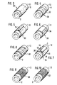
- Fig. 1 shows a longitudinal section through a welding fitting 1 with a body 2, on the inner surface of which the heating coil 4 is arranged in a known manner.
- the wall thickness 6 of the body 2 is comparatively small.
- the outer surface 8 of the essentially cylindrical body 2 is provided with a helical groove 10 which winds around the longitudinal axis 12.
- a winding 14 is embedded in this slot 10.
- the winding 14 is, so to speak, introduced into the slot 10 in an endless process, with relatively large fluctuations being permissible in terms of dimensional accuracy, roundness and diameter tolerances. Special anchorages for the two wire ends 16 are unnecessary.
- the welding sleeve also has a socket 21 with a contact coil 19, via which the power supply to the heating coil 4 takes place.
- the contact coil 19 is formed from the end of the wire of the heating coil 4.
- a further socket with a contact helix is provided at the other end of the sleeve or the weld fitting.
- the winding 14, which is designed as an outer reinforcement, has a length 25, which at least in the context of this invention is the same size as the axial length of the heating coil 4.
- the ends of the winding 14 are at a distance 26 from the end face 28 of the sleeve body 2. Because of this distance, the material required for the reinforcement can be kept small. It is essential that the welding zone or the heating coil 4 is surrounded radially on the outside by the reinforcement and that the material is prevented from radially escaping.
- the inside diameter of the socket body 2 corresponds essentially to the outside diameter of the pipe 15 to be welded. Due to the reinforcement provided according to the invention, the wall thickness 6 of the body 2 is essentially the same or only a small percentage greater than the wall thickness 17 of the pipe 15.
- the wall thickness 6 of the body According to the invention, 2 is at most 10 percent, expediently at most 5 percent, greater than the wall thickness 17 of the pipe 15 to be connected.
- the welding fitting 1 can also be seen from the other side, that is to say in the drawing on the right , One end of a second tube is inserted, which is connected to the tube 15 by means of the weld fitting.
- FIG. 2 shows an enlarged section of a welding sleeve, the wire end 16 bent into a control bore 18 being clearly visible here.
- This welding sleeve can be part of a welding fitting, two or more such sleeves being provided as explained with reference to FIG. 1.
- the welding sleeve can also be arranged at the end of a tube, a branch, a T-piece, a fitting or the like.
- the wire end 16 is pressed somewhat inwards into the control hole 18 in order to prevent it from being inadvertently torn out during transport or on the construction site.
- the individual turns of the winding 14 are at a distance 20 in the direction of the longitudinal axis which is at least as large as the diameter 22 of the wire of the winding.
- the winding or wire is inserted into the helical groove 10 in a continuous process.
- the groove 10 is cut into the outer surface with a knife, whereby lateral material accumulations 24 arise.
- control bore 18 with the wire end 16 is arranged in the axial direction at a distance from the end of the heating coil 4 in FIG. 2.
- the control opening 18 or the wire end of the winding 14 can be arranged in the context of this invention in such a way that, as explained above with reference to FIG. 1, the winding 14 has at least the same axial length as the heating coil 4.
- the reinforcement is designed as a tube 30 which is pressed onto the outer surface 8 of the sleeve body 2.
- a seamlessly drawn or welded metal tube is used.
- the tube is arranged according to the invention with a press fit on the outer surface of the body 2.
- the body is cooled during assembly, as a result of which the diameter of the body 2 is reduced and the tube can be pushed on without problems.
- the tube 30 can also be heated before assembly, so that the press fit is achieved due to the subsequent cooling of the tube.
- the tube arranged on the outer surface 8 consists of three closed ring pieces 32 which have been pushed onto the body 2.
- the assembly is carried out according to the above statements after cooling the body 2 or after heating the ring pieces 32.
- the reinforcement consists of a tube 30 which is rolled from a sheet metal which is connected at its longitudinal edges by means of a flanged seam.
- a rolled sheet metal tube 30 is pressed onto the outer surface of the body 2, the longitudinal sides of which overlap and are connected to one another by means of welding points 36.
- This pipe 30 is preassembled by means of a combined winding and tensioning device, so that the required pretensioning on the reinforcing plate or pipe is ensured during spot welding.
- the tube 30 is formed from a rolled sheet metal which has beads 38 on its two adjacent longitudinal edges.
- the connection takes place with a closure piece 40 which engages in the beads 38 with its inwardly bent ends.
- the closure piece 40 can be pushed parallel to the longitudinal axis 12 in the manner shown.
- the tube consists of two half-shells 44, 46 which are connected in a corresponding manner to a closure piece on the rear side, which is not visible in the drawing. These support half-shells 44, 46 are arranged on the fitting body 2 before welding. After welding, they can be removed again and used again with another fitting 2.
- a single closure piece instead of the two diametrically opposed closure pieces explained, only a single closure piece can be provided, a rolled metal sheet being connected to its longitudinal edges with a single closure piece 40 in accordance with the embodiments of FIGS. 5 and 6.
- the reinforcement is designed according to the invention as a sheet-metal strip 48 wound helically onto the socket body 2.
- the beginning and end of this winding are either mechanically anchored in the sleeve body 2 or connected to the adjacent turns by welding, for example spot welding.
- FIG. 9 shows an essential embodiment, in which the reinforcement is designed as a fiber-reinforced tube 50, which is pressed onto the body 2.
- the pipe 50 prefabricated according to the invention consists of a fiber-reinforced plastic, in particular a glass-fiber-reinforced one Polyester resin, with the fibers arranged with plus / minus 45 degrees windings.
- FIG. 10 shows a special embodiment according to which a laminate 52 made of fiber-reinforced plastic is wound directly onto the fitting body 2.
- a glass fiber-reinforced plastic expediently hardened by the action of light or by thermal action, is used, advantageously polyester resin.
- plus / minus 45 degrees windings are expediently provided.
Landscapes
- Engineering & Computer Science (AREA)
- Mechanical Engineering (AREA)
- General Engineering & Computer Science (AREA)
- Lining Or Joining Of Plastics Or The Like (AREA)
- Branch Pipes, Bends, And The Like (AREA)
- Resistance Welding (AREA)
- Devices For Indicating Variable Information By Combining Individual Elements (AREA)
- Cable Accessories (AREA)
- Storage Of Web-Like Or Filamentary Materials (AREA)
- Professional, Industrial, Or Sporting Protective Garments (AREA)
Claims (10)
- Raccord à souder par électricité (1) ou manchon à souder par électricité, comprenant un corps (2) fait d'une matière thermoplastique et soudable, en particulier de polyoléfine, comme le polyéthylène, équipé d'un fil de chauffage disposé contre la surface intérieure du corps (2), de préférence enroulé en une Spire de chauffage (4), auquel on peut amener du courant pour les soudages, et une armature (14,30) disposée contre la surface extérieure (8) du corps (2), dont l'extrémité se trouve à une distance prédéterminée (36) de la surface frontale (28) du corps (2), caractérisé en ce que l'armature est fixée sur la surface extérieure (8) sous la forme d'un enroulement hélicoïdal (14) ou sous la forme d'un tube (30) fermé sur toute sa circonférence, forme une unité préfabriquée avec le corps (2), et subsiste sur ce corps après le soudage, en ce que , entre l'extrémité de l'armature (14, 30) et la surface frontale (28) du corps (2), est prévue une tubulure (21) servant à l'amenée du courant au fil de chauffage, et en ce que le coefficient de dilatation thermique de l'armature (14, 30) est inférieur au coefficient de dilatation thermique du corps (2) d'un facteur d'au moins 5.
- Raccord à souder par l'électricité selon la Revendication 1, caractérisé en ce que la longueur axiale (25) de l'armature (14, 30) est au moins aussi grande que la longueur de la spire de soudage (4).
- Raccord à souder par l'électricité selon la Revendication 1 ou 2, caractérisé en ce que le coefficient de dilatation themique de l'armature (14,30) est inférieur au coefficient de dilatation thermique du corps (2) d'un facteur d'au moins 10.
- Raccord à souder par l'électricité selon l' une des Revendications 1 à 3, caractérisé en ce que l'enroulement (14) est disposé dans une rainure hélicoïdale (10) pratiquée dans la surface extérieure (8) du corps (2).
- Raccord à souder par l'électricité selon l'une des Revendications 1 à 4, caractérisé en ce qu 'au moins une extrémité (16) de l'enroulement (14) se termine dans un perçage (18) qui est constitué en particulier par un perçage de contrôle et/ou replié radialement vers l'intérieur et ancré dans le corps (2).
- Raccord à souder par l'électricité selon l'une des Revendications 1 à 5, caractérisé en ce que la distance d'écartement axiale (20) entre les spires adjacentes de l'enroulement est au moins égale au diamètre (22) du fil de l'enroulement.
- Raccord à souder par l'électricité selon l'une des Revendications 4 à 6, caractérisé en ce que les digues latérales de matière (24) qui se forment lorsqu'on taille la rainure (10) dans le corps (2) sont refoulées de l'extérieur par dessus le fil de l'enroulement.
- Raccord à souder par l'électricité selon l'une des Revendications 1 à 3, caractérisé en ce que le tube (30) est composé de deux demi-coquilles de soutien (44,46) qui sont reliées l'une à l'autre à l'aide de pièces de fermeture (40).
- Raccord à souder par l'électricité selon l'une des Revendications 1 à 3, caractérisé en ce que le tube (30) est composé d'au moins deux tronçons annulaires (32) disposés axialement l'un à côté de l'autre ou d'une bande de tôle enroulée (48) ou d'une tôle enroulée qui est assemblée le long de ses bords longitudinaux au moyen d'un joint serti ou par une soudure par points (36).
- Raccord à souder par l'électricité selon l'une des Revendications 1 à 3, caractérisé en ce que le tube (30) est constitué par un tube de matière plastique renforcée de fibres, les fibres étant de préférence disposées en enroulements inclinés de plus ou moins 45°, qui sont noyés dans une résine synthétique.
Priority Applications (1)
| Application Number | Priority Date | Filing Date | Title |
|---|---|---|---|
| AT86115185T ATE61863T1 (de) | 1985-11-13 | 1986-11-03 | Elektro-schweissfitting oder elektroschweissmuffe. |
Applications Claiming Priority (2)
| Application Number | Priority Date | Filing Date | Title |
|---|---|---|---|
| DE3540193A DE3540193C1 (de) | 1985-11-13 | 1985-11-13 | Elektro-Schweissfitting oder Schweissmuffe |
| DE3540193 | 1985-11-13 |
Publications (2)
| Publication Number | Publication Date |
|---|---|
| EP0222287A1 EP0222287A1 (fr) | 1987-05-20 |
| EP0222287B1 true EP0222287B1 (fr) | 1991-03-20 |
Family
ID=6285834
Family Applications (1)
| Application Number | Title | Priority Date | Filing Date |
|---|---|---|---|
| EP86115185A Expired - Lifetime EP0222287B1 (fr) | 1985-11-13 | 1986-11-03 | Raccord ou manchon soudable électriquement |
Country Status (7)
| Country | Link |
|---|---|
| US (1) | US4770442A (fr) |
| EP (1) | EP0222287B1 (fr) |
| JP (1) | JPH0615918B2 (fr) |
| AT (1) | ATE61863T1 (fr) |
| AU (1) | AU596384B2 (fr) |
| BR (1) | BR8605599A (fr) |
| DE (2) | DE3540193C1 (fr) |
Cited By (2)
| Publication number | Priority date | Publication date | Assignee | Title |
|---|---|---|---|---|
| EP2672162A1 (fr) | 2012-06-08 | 2013-12-11 | Georg Fischer Wavin AG | Manchon de soudage électrique rainuré |
| DE102015122120A1 (de) | 2015-12-17 | 2017-06-22 | Dirk Pylarski | Schweißelement zum Verbinden mit wenigstens einem Rohrleitungselement |
Families Citing this family (43)
| Publication number | Priority date | Publication date | Assignee | Title |
|---|---|---|---|---|
| US5104468A (en) * | 1984-11-13 | 1992-04-14 | Riesselmann & Sohn | Method of producing a molded connection piece and method for joining tube with molded connection piece |
| JPH0710275B2 (ja) * | 1987-03-04 | 1995-02-08 | 株式会社新素材総合研究所 | 医療用容器およびその製造方法 |
| GB8805911D0 (en) * | 1988-03-12 | 1988-04-13 | Victaulic Plc | Process for jointing of polyolefin bodies |
| US4915417A (en) * | 1988-08-02 | 1990-04-10 | Flo-Control, Inc. | Thermally assembled conduitry |
| JPH02186193A (ja) * | 1989-01-11 | 1990-07-20 | Osaka Gas Co Ltd | エレクトロフュージョン継手 |
| US5252157A (en) * | 1989-05-01 | 1993-10-12 | Central Plastics Company | Electrothermal fusion of large diameter pipes by electric heating wire wrapping and sleeve connector |
| GB2232330B (en) * | 1989-05-01 | 1993-05-26 | Central Plastics Co | A method of connecting pipes |
| FR2648077B1 (fr) * | 1989-06-09 | 1991-10-18 | Boulet D Auria Terlizzi | Procede de raccordement de deux elements tubulaires en matiere plastique par electro-soudage et raccord d'electro-soudage pour la mise en oeuvre de ce procede |
| DE3932807C1 (fr) * | 1989-09-30 | 1991-05-02 | Georg Fischer Ag, Schaffhausen, Ch, Niederlassung: Georg Fischer Ag, 7700 Singen, De | |
| GB2255041B (en) * | 1991-04-24 | 1995-04-19 | British Gas Plc | Polyolefin coupler for joining polyolefin pipes |
| DE4121922C2 (de) * | 1991-07-03 | 1994-06-16 | Friatec Keramik Kunststoff | Reduzierfitting |
| WO1993014342A1 (fr) * | 1992-01-06 | 1993-07-22 | Kubota Corporation | Tuyau en plastique et procede de fabrication associe |
| DE4203626C2 (de) * | 1992-02-08 | 1993-11-04 | Fischer Georg Rohrleitung | Schweissmuffe und verfahren zu deren herstellung |
| US5494318A (en) * | 1993-04-29 | 1996-02-27 | Butts; Nicholas E. | Secondary containment system |
| GB2284179A (en) * | 1993-11-30 | 1995-05-31 | Uponor Aldyl Ltd | Electrofusion coupling element |
| DE4343449C2 (de) * | 1993-12-20 | 1998-01-15 | Friatec Keramik Kunststoff | Verfahren zum Elektroschweißen |
| DE19543083C2 (de) * | 1994-11-28 | 2001-11-15 | Fischer Georg Rohrleitung | Verfahren zum Verbinden aus schweißfähigem Kunststoff bestehender Wellrohre |
| DE19500579C2 (de) * | 1995-01-11 | 1998-05-07 | Fischer Georg Rohrleitung | Formteil aus thermoplastischem Material |
| US5820720A (en) * | 1996-05-28 | 1998-10-13 | Campbell; Steve | Method of and apparatus for electrofusion coupling of thermoplastic pipes |
| US6131954A (en) * | 1996-05-28 | 2000-10-17 | Campbell; Steve | Weldable couple for electrofusion coupling of profile wall thermoplastic pipes without a separate coupler |
| US6521072B1 (en) | 1996-05-28 | 2003-02-18 | C&S Intellectual Properties, Llc | Method of coupling profile wall thermoplastic pipes |
| BR9805029A (pt) * | 1997-11-28 | 1999-11-09 | Friatec Ag | Luva de soldadura |
| US6043466A (en) * | 1998-02-20 | 2000-03-28 | Husky Injection Molding Systems Ltd. | Hot runner heating clamp |
| GB9906057D0 (en) * | 1999-03-17 | 1999-05-12 | British Gas Plc | Joining pipes |
| US6164702A (en) * | 1999-06-07 | 2000-12-26 | Adc Acquisition Company | Reinforced thermoplastic pipe couping |
| US6406063B1 (en) | 1999-07-16 | 2002-06-18 | Fina Research, S.A. | Pipe fittings |
| CA2417954C (fr) * | 2000-08-04 | 2009-11-10 | Friatec Aktiengesellschaft | Dispositif de raccordement d'elements plastiques fusibles |
| US6883835B2 (en) * | 2001-03-05 | 2005-04-26 | Basic Resources, Inc. | Polyfusion pipe repair system and method |
| US6781099B2 (en) * | 2001-03-12 | 2004-08-24 | Karl-Heinz Krah Gmbh | Electrofusion socket forming system |
| US6870143B2 (en) * | 2002-04-18 | 2005-03-22 | Basic Resources, Inc. | System and method for encapsulating a pipe |
| EP1745917B1 (fr) * | 2005-07-18 | 2013-03-06 | Georg Fischer Wavin AG | Manchon d'électrosoudage |
| JP2007146990A (ja) * | 2005-11-29 | 2007-06-14 | Hitachi Metals Ltd | 分岐継手、この分岐継手を用いた消雪スプリンクラ配管ユニット及び消雪パネルユニット、分岐パイプ支持方法 |
| US8418565B2 (en) * | 2006-06-29 | 2013-04-16 | Krohne Ag | Heated pipe connecting device for installation of a flow meter |
| ITMI20062503A1 (it) * | 2006-12-22 | 2008-06-23 | Geco System Spa | Metodo e assieme per riparare giuntare o irrobustire tubi in materiale plastico |
| KR200452685Y1 (ko) * | 2008-10-17 | 2011-03-21 | (주)일진에너지 | 케이블 히터를 구비한 저장용기 |
| DE102009023208A1 (de) | 2009-05-29 | 2010-12-02 | Friatec Aktiengesellschaft | Fitting für ein Rohr |
| FR2963654B1 (fr) * | 2010-08-06 | 2013-12-13 | Saipem Sa | Conduite comportant un chemisage interne et un manchon tubulaire de jonction en matiere plastique |
| WO2013071448A1 (fr) | 2011-11-16 | 2013-05-23 | Flexpipe Systems Inc. | Raccordement pour canalisation thermoplastique, ensemble et procédé |
| JP5503624B2 (ja) * | 2011-11-16 | 2014-05-28 | 古河電気工業株式会社 | 樹脂補強管の接続部の補強構造、補強方法、および補強部材 |
| EP2780159B1 (fr) | 2011-11-16 | 2019-01-09 | Shawcor Ltd. | Tuyau renforcé souple et bande de renfort |
| CA2864762C (fr) | 2012-02-17 | 2019-06-04 | 8193053 Canada Ltd. | Tuyau, raccord de tuyau et systeme de canalisation |
| US11543064B2 (en) | 2017-10-31 | 2023-01-03 | Trelleborg Sealing Solutions Germany Gmbh | Continuous fiber reinforced composite and metal electrofusion coupler |
| JP7638017B1 (ja) * | 2023-10-16 | 2025-03-03 | 株式会社ニチリン | 樹脂製継手付きパイプの製造方法 |
Family Cites Families (18)
| Publication number | Priority date | Publication date | Assignee | Title |
|---|---|---|---|---|
| US2198996A (en) * | 1938-11-15 | 1940-04-30 | Packless Metal Products Corp | Coupling |
| GB821863A (en) * | 1956-10-19 | 1959-10-14 | Crane Packing Ltd | Improvements relating to the joining of synthetic plastic materials, such as pipes |
| NL6412575A (fr) * | 1964-10-29 | 1966-05-02 | ||
| FR1416207A (fr) * | 1964-11-30 | 1965-10-29 | American Metal Prod | Accouplement de conduites en matière plastique |
| NL6601024A (fr) * | 1966-01-27 | 1967-07-28 | ||
| US3519023A (en) * | 1968-08-05 | 1970-07-07 | Ora W Burns Sr | Defrosting collar for pipes |
| US3558164A (en) * | 1968-12-11 | 1971-01-26 | Nat Clay Pipe Inst | Pipe coupling |
| FR2353381A1 (fr) * | 1976-06-03 | 1977-12-30 | Pont A Mousson | Procede d'assemblage par soudure de tubes plastiques et raccord pour un tel assemblage |
| CH622870A5 (fr) | 1977-06-03 | 1981-04-30 | Werner Sturm | |
| US4257630A (en) * | 1978-07-25 | 1981-03-24 | The Goodyear Tire & Rubber Company | Method and apparatus for splicing hose |
| DE3162144D1 (en) * | 1980-03-10 | 1984-03-15 | Fischer Ag Georg | Weld joint for thermoplastic pipes |
| US4530520A (en) * | 1980-03-13 | 1985-07-23 | Von Roll Ag | Electrically weldable bushings |
| US4398754A (en) * | 1980-08-11 | 1983-08-16 | Kerotest Manufacturing Corp. | Electrically insulated pipe coupling and method for making the same |
| US4508368A (en) * | 1982-03-01 | 1985-04-02 | R & G Sloane Mfg. Co., Inc. | Plastic pipe joint |
| US4626308A (en) * | 1983-02-18 | 1986-12-02 | The Victaulic Company Plc | Method of making welded pipe joints |
| SU1107346A1 (ru) * | 1983-06-28 | 1984-08-07 | Институт высоких температур АН СССР | Трубчатый нагреватель из хромита лантана |
| JPS6023596U (ja) * | 1983-07-27 | 1985-02-18 | 三和シヤツタ−工業株式会社 | シャッターのブラケットの取付構造 |
| US4602148A (en) * | 1985-05-16 | 1986-07-22 | Central Plastics Company | Thermoplastic fitting electric heat welding method and apparatus |
-
1985
- 1985-11-13 DE DE3540193A patent/DE3540193C1/de not_active Expired
-
1986
- 1986-11-03 DE DE8686115185T patent/DE3678244D1/de not_active Expired - Lifetime
- 1986-11-03 EP EP86115185A patent/EP0222287B1/fr not_active Expired - Lifetime
- 1986-11-03 AT AT86115185T patent/ATE61863T1/de not_active IP Right Cessation
- 1986-11-12 BR BR8605599A patent/BR8605599A/pt unknown
- 1986-11-12 US US06/929,290 patent/US4770442A/en not_active Expired - Lifetime
- 1986-11-12 AU AU65092/86A patent/AU596384B2/en not_active Expired
- 1986-11-12 JP JP61269502A patent/JPH0615918B2/ja not_active Expired - Lifetime
Cited By (2)
| Publication number | Priority date | Publication date | Assignee | Title |
|---|---|---|---|---|
| EP2672162A1 (fr) | 2012-06-08 | 2013-12-11 | Georg Fischer Wavin AG | Manchon de soudage électrique rainuré |
| DE102015122120A1 (de) | 2015-12-17 | 2017-06-22 | Dirk Pylarski | Schweißelement zum Verbinden mit wenigstens einem Rohrleitungselement |
Also Published As
| Publication number | Publication date |
|---|---|
| BR8605599A (pt) | 1987-08-18 |
| DE3678244D1 (de) | 1991-04-25 |
| AU596384B2 (en) | 1990-05-03 |
| DE3540193C1 (de) | 1987-04-23 |
| US4770442A (en) | 1988-09-13 |
| EP0222287A1 (fr) | 1987-05-20 |
| AU6509286A (en) | 1987-05-21 |
| JPH0615918B2 (ja) | 1994-03-02 |
| JPS62118187A (ja) | 1987-05-29 |
| ATE61863T1 (de) | 1991-04-15 |
Similar Documents
| Publication | Publication Date | Title |
|---|---|---|
| EP0222287B1 (fr) | Raccord ou manchon soudable électriquement | |
| EP0531750B1 (fr) | Procédé pour le soudage de tuyaux en matière thermoplastique | |
| DE2417640A1 (de) | Rohranschlussverbindung | |
| EP0101661B1 (fr) | Rouleau d'appui et/ou rouleau de transport du type à refroidissement interne et procédé de fabrication de ce rouleau | |
| EP0030996A1 (fr) | Arbre d'entraînement en matière synthétique renforcée par des fibres avec mandrin perdu et embouts fixés par enroulement | |
| EP0056080A1 (fr) | Manchon fendu longitudinalement en matière synthétique thermoplastique à mémoire de forme | |
| EP1756464B1 (fr) | Systeme de liaison, en particulier pour l'assemblage par liaison de force d'au moins une piece structurale composite a base de fibres a une autre piece structurale | |
| EP0378607B1 (fr) | Ressort de torsion | |
| DE20010341U1 (de) | Gelenkstange für ein Kraftfahrzeug | |
| DE3435564A1 (de) | Schlauchhalter | |
| DE4224680C2 (de) | Ringförmiges Schweißelement aus Kunststoff zum stirnseitigen Verschweißen von rohrförmigen Kunststoffteilen | |
| DE9304568U1 (de) | Extrudiertes Kunststoff-Metall-Verbundrohr für Installationen | |
| DE4028237C2 (fr) | ||
| DE3841064A1 (de) | Rohr zum zwecke der rohrauskleidung | |
| EP0485651A1 (fr) | Outil pour soudage par polyfusion des tuyaux extrudés en matière plastique-aluminium avec des embouts ou des pièces moulées | |
| DE19543083C2 (de) | Verfahren zum Verbinden aus schweißfähigem Kunststoff bestehender Wellrohre | |
| WO2009033603A1 (fr) | Procédé de soudage de tuyaux en plastique | |
| DE202020107574U1 (de) | Antriebsvorrichtung mit einer Stützvorrichtung | |
| DE19547821A1 (de) | Rohr o. dgl. Formstück aus thermoplastischem Kunststoff und Verfahren zu seiner Herstellung | |
| DE19524903A1 (de) | Wellenförmige Kraftübertragungseinrichtung in faserverstärkte Rahmenstrukturen sowie Verfahren zu ihrer Herstellung | |
| WO2011000509A1 (fr) | Bague de serrage pour tuyaux flexibles | |
| EP1506921A1 (fr) | Dispositif rétractable pour un sous-marin et méthode de fabrication | |
| DE69510770T2 (de) | Rohrverbindung und Verfahren zur seiner Herstellung | |
| DE19606574A1 (de) | Verfahren zum Aufbringen einer rohrförmigen Ummantelung auf ein Zugglied | |
| DE4343449C2 (de) | Verfahren zum Elektroschweißen |
Legal Events
| Date | Code | Title | Description |
|---|---|---|---|
| PUAI | Public reference made under article 153(3) epc to a published international application that has entered the european phase |
Free format text: ORIGINAL CODE: 0009012 |
|
| 17P | Request for examination filed |
Effective date: 19861103 |
|
| AK | Designated contracting states |
Kind code of ref document: A1 Designated state(s): AT BE CH DE FR GB IT LI NL SE |
|
| 17Q | First examination report despatched |
Effective date: 19881219 |
|
| GRAA | (expected) grant |
Free format text: ORIGINAL CODE: 0009210 |
|
| AK | Designated contracting states |
Kind code of ref document: B1 Designated state(s): AT BE CH DE FR GB IT LI NL SE |
|
| REF | Corresponds to: |
Ref document number: 61863 Country of ref document: AT Date of ref document: 19910415 Kind code of ref document: T |
|
| ET | Fr: translation filed | ||
| REF | Corresponds to: |
Ref document number: 3678244 Country of ref document: DE Date of ref document: 19910425 |
|
| ITF | It: translation for a ep patent filed | ||
| GBT | Gb: translation of ep patent filed (gb section 77(6)(a)/1977) | ||
| PLBI | Opposition filed |
Free format text: ORIGINAL CODE: 0009260 |
|
| 26 | Opposition filed |
Opponent name: GEORG FISCHER ROHRLEITUNGSSYSTEME AG Effective date: 19911204 |
|
| NLR1 | Nl: opposition has been filed with the epo |
Opponent name: GEORG FISCHER ROHRLEITUNGSSYSTEME AG |
|
| REG | Reference to a national code |
Ref country code: CH Ref legal event code: PFA Free format text: FRIEDRICHSFELD AG KERAMIK- UND KUNSTSTOFFWERKE |
|
| RAP2 | Party data changed (patent owner data changed or rights of a patent transferred) |
Owner name: FRIEDRICHSFELD AKTIENGESELLSCHAFT KERAMIK- UND KUN |
|
| RAP2 | Party data changed (patent owner data changed or rights of a patent transferred) |
Owner name: FRIATEC AKTIENGESELLSCHAFT KERAMIK- UND KUNSTSTOFF |
|
| REG | Reference to a national code |
Ref country code: FR Ref legal event code: CN |
|
| REG | Reference to a national code |
Ref country code: CH Ref legal event code: PFA Free format text: FRIATEC AKTIENGESELLSCHAFT KERAMIK- UND KUNSTSTOFFWERKE |
|
| NLS | Nl: assignments of ep-patents |
Owner name: FRIEDRICHSFELD AKTIENGESELLSCHAFT KERAMIK- UND KUN |
|
| PLBN | Opposition rejected |
Free format text: ORIGINAL CODE: 0009273 |
|
| STAA | Information on the status of an ep patent application or granted ep patent |
Free format text: STATUS: OPPOSITION REJECTED |
|
| 27O | Opposition rejected |
Effective date: 19930830 |
|
| NLT1 | Nl: modifications of names registered in virtue of documents presented to the patent office pursuant to art. 16 a, paragraph 1 |
Owner name: FRIATEC AKTIENGESELLSCHAFT KERAMIK- UND KUNSTSTOFF |
|
| NLR2 | Nl: decision of opposition | ||
| REG | Reference to a national code |
Ref country code: FR Ref legal event code: CD |
|
| EAL | Se: european patent in force in sweden |
Ref document number: 86115185.0 |
|
| REG | Reference to a national code |
Ref country code: GB Ref legal event code: IF02 |
|
| PGFP | Annual fee paid to national office [announced via postgrant information from national office to epo] |
Ref country code: GB Payment date: 20051019 Year of fee payment: 20 |
|
| PGFP | Annual fee paid to national office [announced via postgrant information from national office to epo] |
Ref country code: NL Payment date: 20051117 Year of fee payment: 20 |
|
| PGFP | Annual fee paid to national office [announced via postgrant information from national office to epo] |
Ref country code: FR Payment date: 20051118 Year of fee payment: 20 |
|
| PGFP | Annual fee paid to national office [announced via postgrant information from national office to epo] |
Ref country code: SE Payment date: 20051122 Year of fee payment: 20 Ref country code: AT Payment date: 20051122 Year of fee payment: 20 |
|
| REG | Reference to a national code |
Ref country code: GB Ref legal event code: PE20 |
|
| PGFP | Annual fee paid to national office [announced via postgrant information from national office to epo] |
Ref country code: CH Payment date: 20051123 Year of fee payment: 20 Ref country code: BE Payment date: 20051123 Year of fee payment: 20 |
|
| PGFP | Annual fee paid to national office [announced via postgrant information from national office to epo] |
Ref country code: IT Payment date: 20051125 Year of fee payment: 20 |
|
| PGFP | Annual fee paid to national office [announced via postgrant information from national office to epo] |
Ref country code: DE Payment date: 20051130 Year of fee payment: 20 |
|
| PG25 | Lapsed in a contracting state [announced via postgrant information from national office to epo] |
Ref country code: GB Free format text: LAPSE BECAUSE OF EXPIRATION OF PROTECTION Effective date: 20061102 |
|
| PG25 | Lapsed in a contracting state [announced via postgrant information from national office to epo] |
Ref country code: NL Free format text: LAPSE BECAUSE OF EXPIRATION OF PROTECTION Effective date: 20061103 |
|
| REG | Reference to a national code |
Ref country code: CH Ref legal event code: PL |
|
| NLV7 | Nl: ceased due to reaching the maximum lifetime of a patent |
Effective date: 20061103 |
|
| EUG | Se: european patent has lapsed | ||
| BE20 | Be: patent expired |
Owner name: *FRIATEC A.G. KERAMIK-UND KUNSTSTOFFWERKE Effective date: 20061103 |
|
| PLAB | Opposition data, opponent's data or that of the opponent's representative modified |
Free format text: ORIGINAL CODE: 0009299OPPO |