EP0222293A2 - Optisches Strahlenteilerprisma - Google Patents
Optisches Strahlenteilerprisma Download PDFInfo
- Publication number
- EP0222293A2 EP0222293A2 EP86115217A EP86115217A EP0222293A2 EP 0222293 A2 EP0222293 A2 EP 0222293A2 EP 86115217 A EP86115217 A EP 86115217A EP 86115217 A EP86115217 A EP 86115217A EP 0222293 A2 EP0222293 A2 EP 0222293A2
- Authority
- EP
- European Patent Office
- Prior art keywords
- prism
- parallel
- input
- output
- connector
- Prior art date
- Legal status (The legal status is an assumption and is not a legal conclusion. Google has not performed a legal analysis and makes no representation as to the accuracy of the status listed.)
- Granted
Links
Images
Classifications
-
- G—PHYSICS
- G02—OPTICS
- G02B—OPTICAL ELEMENTS, SYSTEMS OR APPARATUS
- G02B6/00—Light guides; Structural details of arrangements comprising light guides and other optical elements, e.g. couplings
- G02B6/24—Coupling light guides
- G02B6/26—Optical coupling means
- G02B6/28—Optical coupling means having data bus means, i.e. plural waveguides interconnected and providing an inherently bidirectional system by mixing and splitting signals
- G02B6/293—Optical coupling means having data bus means, i.e. plural waveguides interconnected and providing an inherently bidirectional system by mixing and splitting signals with wavelength selective means
- G02B6/29371—Optical coupling means having data bus means, i.e. plural waveguides interconnected and providing an inherently bidirectional system by mixing and splitting signals with wavelength selective means operating principle based on material dispersion
- G02B6/29373—Optical coupling means having data bus means, i.e. plural waveguides interconnected and providing an inherently bidirectional system by mixing and splitting signals with wavelength selective means operating principle based on material dispersion utilising a bulk dispersive element, e.g. prism
-
- G—PHYSICS
- G02—OPTICS
- G02B—OPTICAL ELEMENTS, SYSTEMS OR APPARATUS
- G02B27/00—Optical systems or apparatus not provided for by any of the groups G02B1/00 - G02B26/00, G02B30/00
- G02B27/10—Beam splitting or combining systems
- G02B27/1006—Beam splitting or combining systems for splitting or combining different wavelengths
-
- G—PHYSICS
- G02—OPTICS
- G02B—OPTICAL ELEMENTS, SYSTEMS OR APPARATUS
- G02B27/00—Optical systems or apparatus not provided for by any of the groups G02B1/00 - G02B26/00, G02B30/00
- G02B27/10—Beam splitting or combining systems
- G02B27/1073—Beam splitting or combining systems characterized by manufacturing or alignment methods
-
- G—PHYSICS
- G02—OPTICS
- G02B—OPTICAL ELEMENTS, SYSTEMS OR APPARATUS
- G02B27/00—Optical systems or apparatus not provided for by any of the groups G02B1/00 - G02B26/00, G02B30/00
- G02B27/10—Beam splitting or combining systems
- G02B27/14—Beam splitting or combining systems operating by reflection only
-
- G—PHYSICS
- G02—OPTICS
- G02B—OPTICAL ELEMENTS, SYSTEMS OR APPARATUS
- G02B27/00—Optical systems or apparatus not provided for by any of the groups G02B1/00 - G02B26/00, G02B30/00
- G02B27/10—Beam splitting or combining systems
- G02B27/14—Beam splitting or combining systems operating by reflection only
- G02B27/144—Beam splitting or combining systems operating by reflection only using partially transparent surfaces without spectral selectivity
-
- G—PHYSICS
- G02—OPTICS
- G02B—OPTICAL ELEMENTS, SYSTEMS OR APPARATUS
- G02B27/00—Optical systems or apparatus not provided for by any of the groups G02B1/00 - G02B26/00, G02B30/00
- G02B27/28—Optical systems or apparatus not provided for by any of the groups G02B1/00 - G02B26/00, G02B30/00 for polarising
- G02B27/283—Optical systems or apparatus not provided for by any of the groups G02B1/00 - G02B26/00, G02B30/00 for polarising used for beam splitting or combining
-
- G—PHYSICS
- G02—OPTICS
- G02B—OPTICAL ELEMENTS, SYSTEMS OR APPARATUS
- G02B6/00—Light guides; Structural details of arrangements comprising light guides and other optical elements, e.g. couplings
- G02B6/24—Coupling light guides
- G02B6/26—Optical coupling means
- G02B6/28—Optical coupling means having data bus means, i.e. plural waveguides interconnected and providing an inherently bidirectional system by mixing and splitting signals
- G02B6/2804—Optical coupling means having data bus means, i.e. plural waveguides interconnected and providing an inherently bidirectional system by mixing and splitting signals forming multipart couplers without wavelength selective elements, e.g. "T" couplers, star couplers
- G02B6/2817—Optical coupling means having data bus means, i.e. plural waveguides interconnected and providing an inherently bidirectional system by mixing and splitting signals forming multipart couplers without wavelength selective elements, e.g. "T" couplers, star couplers using reflective elements to split or combine optical signals
Definitions
- This invention relates to optical beam splitter prisms and, in particular, to optical beam splitter prisms having orientation insensitivity. Accordingly, it is a general object of this invention to provide new and improved optical beam splitter prisms of such character.
- An optical beam splitter is based upon the separation of an incident wave, at a partially reflecting interface between two transparent media, into a reflected wave and a transmitted wave.
- the interface may consist of a thin metallic layer or it may consist of a multilayer thin film stack of dielectric coatings or it may consist of a combination thereof, and may be designed to reflect part of the beam intensity regardless of its polarization state or wavelength, or so as to selectively reflect one polarization state, or a band of wavelengths, and to transmit the remaining light energy.
- the interface is usually planar to avoid defocusing an applied beam upon reflection.
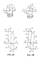
- a glass prism assembly usually supports the interface layers and provides for the light beam entrances and exits. Such a cube type beam splitter of the prior art is depicted in Fig. 1A.
- An incident optical beam 11 enters a glass beam splitter 12, as depicted in Fig. 1A, and passes through a first 45° prism half 13 to an interface 14. Part of the beam intensity is reflected and leaves the prism half 13 as a first output beam 16, while the remaining intensity is transmitted through a second 45° prism half 17 and leaves as a second output beam 18.
- the beam 16 is nominally ninety degrees in direction from that of the beam 18, but if, as depicted in Fig. 1B, the prism 12 is rotationally misaligned, the output beam 16 is changed in direction relative to the input beam 11.
- the output beam 18, having been refracted twice by the parallel facets of the beam splitter 12, is laterally displaced by a small amount but is still parallel to the input beam 11.
- Beam splitter prism devices are useful in fiber optic systems.
- the light from an optical fiber is focused into a parallel beam by a small lens, passed through a prism, and then refocused back into another fiber.
- the small lenses, affixed to the fiber with their focal point at the end of the fiber core, are known as expanded beam lens connectors and serve as convenient interfaces between light in a fiber and light in a parallel beam.
- the input parallel beam should have a high degree of angular accuracy with respect to the lens axis. Due to the expanded cross-sectional area of the parallel beam, lateral positioning is of secondary importance.
- Another object of the present invention is to provide a new and improved optical beam splitter prism in which all input and output beams are parallel and remain parallel while the prism is rotationally misaligned about any axis.
- Still another object of the present invention is to provide a new and improved interference filter type wavelength multiplexer utilizing an optical beam splitter prism in which all input and output beams are parallel and remain parallel while the prism is rotationally misaligned about any axis.
- Yet another object of the invention is to provide a new and improved birefringent type filter utilizing new and improved optical beam splitter prisms in which all input and output beams are parallel and remain parallel while the prisms are rotationally misaligned about any axis.
- an improved beam splitter prism includes a pair of prism sections joined together at an optical interface within which a partially transmitting optical coating is present.
- the improved prism is characterized by at least one of the sections having a respective, planar, reflective surface; and where each of the prism sections has a respective, planar, optical interface surface joined together within which the coating is present, wherein each of the planar reflective surfaces is parallel to each of the planar, optical interface surfaces and to each other.
- the prism has planar input and output surfaces that are parallel to each other.
- the foregoing partially transmitting optical coating can be selected from the group consisting of a thin metallic layer, a multilayer thin film stack of dielectric coatings, and a combination thereof.
- a first input beam applied to the planar input surface is reflected by the reflective surface of one of the prism sections to the optical interface.
- light having a first characteristic is transmitted through the optical interface to the reflective surface of the other prism section and is reflected outward through the output surface as a first output light beam having that first characteristic.
- Light having a second characteristic is reflected by the coating through the output surface as a second output light beam having that second characteristic.
- the first output light beam and the second output light beam are both parallel to the input light beam and to each other.
- two input beams and two output beams have components having a first characteristic and a second characteristic. As the input beams reach the optical interface, those components having the first characteristic are transmitted therethrough, and those having the second characteristic are reflected by the optical interface.
- One output beam contains the first characteristic of the first input beam and the second characteristic of the second output beam.
- the other output beam contains the first characteristic of the second input beam and the second characteristic of the first input beam.
- an interference filter type wavelength multiplexer includes a pair of prism sections joined together at an optical interface within which a partially transmitting optical coating is present.
- the coating consists of a multilayer stack of dielectric films that selectively reflects according to wavelength the beams incident thereto.
- the joined prism sections form (with the coating) a beam splitter prism.
- At least one prism section has a respective, planar, reflective surface, and each prism section has a respective, planar, optical interface surface joined together within which the coating is present.
- Each of the planar reflective surfaces is parallel to each of the planar, optical, interface surfaces and to each other.
- the prism has a planar input surface and a planar output surface that are parallel to each other.
- a housing is provided for the beam splitter prism.
- the housing has a first planar reference surface in proximity to, and in general parallelism with, the input surface of the prism, and has a second planar reference surface in proximity to, and in general parallelism with, the output surface of the prism.
- the first planar reference surface is precisely parallel to the second planar reference surface.
- a plurality of expanded beam optical connectors each having an optical axis, a planar reference surface perpendicular to the axis, a lens surface and means for orienting an optical fiber therewithin are provided. The reference surfaces of the connectors are engaged with the reference surfaces of the housing.
- a birefringent filter type wavelength multiplexer/demultiplexer includes a housing for retaining various optical components such as beam splitter prisms and a birefringent element.
- the housing has a pair of opposed walls whose external surfaces are parallel to each other, each wall having a pair of orifices therethrough.
- First and second expanded beam lens connectors each having a lens for projecting light from a suitable source (such as optical fiber), are coupled to the external surface of one housing wall and aligned therewith via respective flat reference surfaces on the connectors, which reference surfaces are perpendicular to the optical axes thereof.
- Third and fourth expanded beam connectors are coupled to the external surface of the other housing wall so as to provide outputs to optical fiber coupled thereto.
- Reference surfaces of the connectors engage the flat external surface of the aforesaid other housing wall.
- the flat reference surfaces are perpendicular to the axes of the third and fourth connectors. All four connectors are coupled with their reference surfaces in engagement with the external surfaces of the housing at the various orifices thereof.
- a first beam splitter prism receives a first, applied, input expanded beam of light along a first optical axis; the second expanded beam of light is applied along the second optical axis as a second input beam thereto, thereby providing a pair of parallel split beams each having different pairs of polarization states from the first expanded and the second expanded beam.
- a birefringent element oriented to receive the parallel split beams, issues a pair of parallel beams.
- One of the issued parallel beams is applied as one input beam to a second beam splitter prism; the other of the issued parallel beams is applied as the other input of the second beam splitter prism, thereby passing energy at one wavelength from the first connector to the third connector and from the second connector to the fourth connector.
- Another wavelength is applied from the first connector to the fourth connector and from the second connector to the third connector.
- the first expanded beam and the second expanded beam entering the first beam splitter prism, and the third expanded beam and the fourth expanded beam exiting from the second beam splitter prism are parallel and remain parallel as the prisms are translationally or rotationally misaligned.
- the prism design of the present invention is depicted in Fig. 2A. It consists of two prism sections 21 and 22 joined together, as by cement, at an interface 23 within which is present a partially transmitting coating.
- This coating may be a thin semitransparent metallic film or a multilayer thin film stack of dielectric coatings or a combination thereof to unselectively reflect part of the light energy or to selectively reflect one polarization state or one band of wavelengths and transmit the remaining light energy.
- Prism facets 24 and 26 are precisely ground and polished to be parallel to each other and to the interface 23.
- Prism facets 27 and 28, which extend across the interface onto the section 22, are also ground and polished to be parallel to each other.
- An input light beam 29 enters the prism section 21 and is reflected by the facet 24. It is partially reflected at the interface 23 and exits as an output beam 31 through the facet 28. The remaining light energy is transmitted into the prism section 22, reflected at the facet 26 and exits as an output beam 32, also through the facet 28.
- the reflecting surfaces 24 and 26 may be given mirror coatings or the reflection may be via total internal reflection if a suitably large refractive index material is chosen to construct the prism sections 21 and 22.
- An alternate input light beam 33 can enter the prism section 22, wherein it is partially transmitted at the interface 23 into the prism section 21 and exits as an output 31 through the facet 28.
- Parallel prism facets 23, 24, and 26 are depicted at a nominal 45° orientation to the parallel prism facets 27, 28. However, other angles are also suitable.
- Lateral deviations of the output beams as the prism is rotated or translated can be readily calculated with the help of a geometric construction (not shown).
- the optical path, from where the input beam 29 enters the facet 27 to where the output beam 32 exits the facet 28, is equivalent to a straight passage of a beam through a parallel plate having a thickness t equal to the path length through the original beam splitting prism.
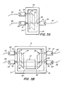
- FIG. 3A Two applications of this improved beam splitter in specific devices for fiber optic systems are shown in Figs. 3A and 3B.
- An interference filter type wavelength multiplexer is shown schematically in Fig. 3A.
- expanded beam lens connectors 41, 42 and 43 attached to the ends of optical fibers 44, 46 and 47, respectively are pressed into contact with a metal housing 48 such that their forward flat reference surfaces 49, 51 and 52, respectively, coincide with either of the flat and parallel alignment surfaces 53 and 54 of the housing 48.
- these forward reference surfaces accurately define the connector lens axes, this insures that the beams 56, 57 and 58, exiting the connectors 41 and 42 and entering the connector 43, are precisely parallel.
- a beam splitter prism 59 constructed as detailed hereinabove in connection with Fig. 2A, intercepts these beams and connects their paths, but since output beam 32 of Fig. 2A is not utilized, parallel prism facet 26 is not needed and may be omitted.
- the beam splitter prism 59 can be installed in the housing 48 with a considerable tolerance to both translational and rotational misorientation due to its design according to the present invention.
- At the interface 23 there exists a multilayer stack of dielectric films that selectively reflects according to wavelength the beams that are incident upon it. The design of such multilayer films for the interface is well known in the art.
- the fibers 44 and 46 serve as the input signals at two different wavelengths. The output signal from the fiber 44 is reflected at the interface 23 while that from the fiber 46 is transmitted at the interface 23, and both combine as an output beam 58 to be coupled to the output fiber 47.
- the same configuration is operable in reverse as a wavelength demultiplexer.
- FIG. 3B A birefringent filter type wavelength multiplexer or demultiplexer is depicted in Fig. 3B.
- expanded beam lens connectors 61, 62, 63, and 64 attached to the ends of optical fibers 66, 67, 68, and 69 are pressed into contact with a metal housing 71 such that their forward flat reference surfaces 72, 73, 74, and 76 coincide with either of the flat and parallel alignment surfaces 77 and 78 of the housing 71.
- Beam splitter prisms 84 and 86 constructed as in Fig.
- the beam splitters 84 and 86 When used as a part of a birefringent filter type optical multiplexer/demultiplexer assembly, as shown in Fig. 3B, the beam splitters 84 and 86 selectively reflect one polarization state and transmit the other at the interface 23.
- the design of such multilayer films for the interface is well known in the art.
- the birefringent element 87 may be a single crystal of a crystalline material such as quartz or calcite oriented with its principal axes of birefringence at an angle of 45 degrees relative to the principal polarization axes of beam splitters 84 and 86.
- This birefringent multiplexer/demultiplexer passes energy at one wavelength from the fiber 67 to the fiber 66 and from the fiber 68 to the fiber 69 and at another wavelength from the fiber 67 to the fiber 69 and from the fiber 68 to the fiber 66.
- These inputs do not need to have a specific polarization state as both polarization components are processed simultaneously by this device.
Landscapes
- Physics & Mathematics (AREA)
- General Physics & Mathematics (AREA)
- Optics & Photonics (AREA)
- Spectroscopy & Molecular Physics (AREA)
- Engineering & Computer Science (AREA)
- Manufacturing & Machinery (AREA)
- Chemical & Material Sciences (AREA)
- Dispersion Chemistry (AREA)
- Optical Couplings Of Light Guides (AREA)
- Optical Elements Other Than Lenses (AREA)
Applications Claiming Priority (2)
| Application Number | Priority Date | Filing Date | Title |
|---|---|---|---|
| US06/796,331 US4671613A (en) | 1985-11-12 | 1985-11-12 | Optical beam splitter prism |
| US796331 | 1985-11-12 |
Publications (3)
| Publication Number | Publication Date |
|---|---|
| EP0222293A2 true EP0222293A2 (de) | 1987-05-20 |
| EP0222293A3 EP0222293A3 (en) | 1987-11-25 |
| EP0222293B1 EP0222293B1 (de) | 1992-07-29 |
Family
ID=25167931
Family Applications (1)
| Application Number | Title | Priority Date | Filing Date |
|---|---|---|---|
| EP86115217A Expired EP0222293B1 (de) | 1985-11-12 | 1986-11-03 | Optisches Strahlenteilerprisma |
Country Status (5)
| Country | Link |
|---|---|
| US (1) | US4671613A (de) |
| EP (1) | EP0222293B1 (de) |
| JP (1) | JPS62113103A (de) |
| CA (1) | CA1284909C (de) |
| DE (1) | DE3686234T2 (de) |
Cited By (4)
| Publication number | Priority date | Publication date | Assignee | Title |
|---|---|---|---|---|
| EP0469718A3 (en) * | 1990-07-03 | 1993-10-13 | Konica Corporation | Laser interferometry length measuring apparatus |
| WO1996002114A1 (de) * | 1994-07-08 | 1996-01-25 | Forschungszentrum Karlsruhe Gmbh | 3d-video-endoskop |
| US5944655A (en) * | 1994-07-08 | 1999-08-31 | Forschunjszentrum Karlsruhe Gmbh | 3D endoscope with optical switch and prism arrangement |
| DE10054370A1 (de) * | 2000-10-30 | 2002-05-16 | Infineon Technologies Ag | Optisches Verteilerelement |
Families Citing this family (45)
| Publication number | Priority date | Publication date | Assignee | Title |
|---|---|---|---|---|
| CA1250170A (en) * | 1985-07-16 | 1989-02-21 | Jerzy A. Dobrowolski | Optical mixing/demixing device |
| US4859029A (en) * | 1986-07-03 | 1989-08-22 | Durell William E | Variable ratio beam splitter and beam launcher |
| US4787710A (en) * | 1986-07-03 | 1988-11-29 | Durell William E | Variable ratio beam splitter |
| JPS63304222A (ja) * | 1987-06-04 | 1988-12-12 | Minolta Camera Co Ltd | レ−ザ光源装置 |
| JPS6454401A (en) * | 1987-08-26 | 1989-03-01 | Fuji Electrochemical Co Ltd | Prism for optical switch |
| US4790621A (en) * | 1987-12-07 | 1988-12-13 | Gte Products Corporation | Fiber optic switch |
| US4872737A (en) * | 1988-09-07 | 1989-10-10 | Hitachi Cable Limited | Multi-port fiberoptic rotary joint |
| US5223975A (en) * | 1988-11-11 | 1993-06-29 | Fujitsu Limited | Polarization beam coupler including a splitter for producing an output monitor beam |
| US4988170A (en) * | 1989-03-31 | 1991-01-29 | Gte Laboratories Incorporated | Quasi-achromatic optical isolators and circulators |
| US4991938A (en) * | 1989-04-07 | 1991-02-12 | Gte Laboratories Incorporated | Quasi-achromatic optical isolators and circulators using prisms with total internal fresnel reflection |
| US5136433A (en) * | 1990-05-29 | 1992-08-04 | Durell William E | Optical positioner and connector |
| JPH04191703A (ja) * | 1990-11-27 | 1992-07-10 | Fujitsu Ltd | 偏光無依存性光学部品 |
| US5583683A (en) * | 1995-06-15 | 1996-12-10 | Optical Corporation Of America | Optical multiplexing device |
| US6163393A (en) | 1996-10-29 | 2000-12-19 | Chorum Technologies Inc. | Method and apparatus for wavelength multipexing/demultiplexing |
| US6243200B1 (en) | 2000-03-02 | 2001-06-05 | Chorum Technologies, Inc. | Optical wavelength router based on polarization interferometer |
| US6847786B2 (en) | 1996-10-29 | 2005-01-25 | Ec-Optics Technology, Inc. | Compact wavelength filter using optical birefringence and reflective elements |
| US6115155A (en) | 1996-10-29 | 2000-09-05 | Chorum Technologies Inc. | System for dealing with faults in an optical link |
| US6545783B1 (en) | 1996-10-29 | 2003-04-08 | Chorum Technologies Lp | Optical wavelength add/drop multiplexer |
| US6038076A (en) * | 1997-12-03 | 2000-03-14 | Noran Instruments, Inc. | Wavelength selection, multiplexing and demultiplexing method and apparatus |
| WO2000011510A1 (en) * | 1998-08-21 | 2000-03-02 | Corning Incorporated | Tunable periodic filter |
| EP1031868B1 (de) * | 1999-02-26 | 2003-05-14 | Dr. Johannes Heidenhain GmbH | Kompensierter Parallel-Strahlteiler mit zwei Platten sowie Interferometer |
| US6519060B1 (en) | 1999-06-04 | 2003-02-11 | Chorum Technologies Lp | Synchronous optical network in frequency domain |
| US6282025B1 (en) * | 1999-08-02 | 2001-08-28 | New Focus, Inc. | Optical polarization beam combiner/splitter |
| US6574385B2 (en) * | 2000-01-18 | 2003-06-03 | Jds Uniphase Inc. | M×N optical switch with improved stability |
| CN1196949C (zh) * | 2000-03-17 | 2005-04-13 | 康宁股份有限公司 | 光波导透镜和制造方法 |
| KR100393215B1 (ko) * | 2001-02-13 | 2003-07-31 | 삼성전자주식회사 | 플레이트형 빔스프리터 및 그 제조방법 및 이를 채용한광픽업장치 |
| US6515786B1 (en) | 2001-08-03 | 2003-02-04 | Chorum Technologies Lp | Bandwidth variable wavelength router and method of operation |
| US6954592B2 (en) * | 2002-01-24 | 2005-10-11 | Jds Uniphase Corporation | Systems, methods and apparatus for bi-directional optical transceivers |
| US7244937B1 (en) * | 2002-10-15 | 2007-07-17 | Raytheon Company | Optical measurement apparatus with laser light source |
| JP4393094B2 (ja) * | 2003-04-10 | 2010-01-06 | キヤノン株式会社 | 光学系 |
| US7181102B1 (en) * | 2004-05-21 | 2007-02-20 | Optiworks, Inc. | Optical switching systems and methods |
| US7130062B2 (en) * | 2005-01-28 | 2006-10-31 | Raytheon Company | Rapid-response electron-beam deposition system having a controller utilizing leading and trailing deposition indicators |
| US7661889B2 (en) * | 2006-04-14 | 2010-02-16 | Beam Express Inc | Optical multiplexer and transmitter |
| US20090098316A1 (en) * | 2007-10-15 | 2009-04-16 | Bree Cox | Decorative upholstery tack |
| CN101299075B (zh) * | 2008-05-30 | 2010-12-08 | 福州高意通讯有限公司 | 一种可调滤光片光学结构及具有该结构的光谱分析仪 |
| JP5278819B2 (ja) * | 2009-05-11 | 2013-09-04 | 株式会社リコー | ステレオカメラ装置及びそれを用いた車外監視装置 |
| US8456637B2 (en) | 2010-08-26 | 2013-06-04 | Mitutoyo Corporation | Multiple measuring point configuration for a chromatic point sensor |
| US8194251B2 (en) | 2010-08-26 | 2012-06-05 | Mitutoyo Corporation | Method for operating a dual beam chromatic point sensor system for simultaneously measuring two surface regions |
| US8355207B2 (en) * | 2010-09-08 | 2013-01-15 | Lightmachinery Inc. | Angular adjustable variable beamsplitter |
| KR102603829B1 (ko) | 2014-11-13 | 2023-11-17 | 에이엠에스-오스람 아시아 퍼시픽 피티이. 리미티드 | 광학 도광체의 제조 |
| EP3236308B1 (de) | 2016-04-19 | 2018-08-15 | LIMO GmbH | Laservorrichtung |
| US10416471B2 (en) * | 2016-10-17 | 2019-09-17 | Cymer, Llc | Spectral feature control apparatus |
| US10469195B2 (en) * | 2017-10-12 | 2019-11-05 | Luxtera, Inc. | Method and system for eliminating polarization dependence for 45 degree incidence MUX/DEMUX designs |
| US11360294B2 (en) | 2020-05-15 | 2022-06-14 | Samsung Electronics Co., Ltd. | Optical sensor |
| RU2736920C1 (ru) * | 2020-05-15 | 2020-11-23 | Самсунг Электроникс Ко., Лтд. | Многофункциональный миниатюрный оптический датчик для дистанционного обнаружения микро- и макрообъектов и для измерения характеристик обнаруженных объектов |
Family Cites Families (14)
| Publication number | Priority date | Publication date | Assignee | Title |
|---|---|---|---|---|
| FR856528A (fr) * | 1939-03-03 | 1940-06-17 | Procédé de cinématographie en couleurs, dispositifs optiques pour son applicationet produits en résultant | |
| US3068743A (en) * | 1959-04-08 | 1962-12-18 | Ass Elect Ind | Optical apparatus for measuring small distances |
| US3501640A (en) * | 1967-01-13 | 1970-03-17 | Ibm | Optical communication system |
| CH556548A (de) * | 1972-09-19 | 1974-11-29 | Balzers Patent Beteilig Ag | Aus abwechselnd hoch- und niederbrechenden oxidschichten aufgebautes verlustarmes, hochreflektierendes vielschichtsystem. |
| JPS53130047A (en) * | 1977-04-20 | 1978-11-13 | Sumitomo Electric Ind Ltd | Photo coupling circuit |
| DE3010347C2 (de) * | 1980-03-18 | 1984-08-30 | Fa. Carl Zeiss, 7920 Heidenheim | Einrichtung zur Verbindung von Lichtleitern |
| JPS57185410A (en) * | 1981-05-11 | 1982-11-15 | Kokusai Denshin Denwa Co Ltd <Kdd> | Optical coupler |
| DE3135205A1 (de) * | 1981-09-05 | 1983-03-17 | Philips Kommunikations Industrie AG, 8500 Nürnberg | Einstellbarer optischer strahlteiler |
| FR2516254B1 (fr) * | 1981-11-12 | 1985-09-13 | Comp Generale Electricite | Separateur optique pour la separation ou la superposition de deux faisceaux de lumiere |
| US4514046A (en) * | 1981-12-07 | 1985-04-30 | Gte Laboratories Incorporated | Polarization-insensitive optical switch and multiplexing apparatus |
| US4540246A (en) * | 1983-03-28 | 1985-09-10 | Polaroid Corporation | Holographic optical apparatus for use with expanded-beam type fiber optical components |
| DE3413704A1 (de) * | 1984-04-12 | 1985-10-24 | Standard Elektrik Lorenz Ag, 7000 Stuttgart | Optischer leistungsteiler |
| DE3413703A1 (de) * | 1984-04-12 | 1985-10-24 | Standard Elektrik Lorenz Ag, 7000 Stuttgart | Optischer multiplexer/demultiplexer |
| US4566761A (en) * | 1984-09-13 | 1986-01-28 | Gte Laboratories Incorporated | Birefringent optical wavelength multiplexer/demultiplexer |
-
1985
- 1985-11-12 US US06/796,331 patent/US4671613A/en not_active Expired - Lifetime
-
1986
- 1986-10-07 CA CA000519977A patent/CA1284909C/en not_active Expired - Fee Related
- 1986-11-03 EP EP86115217A patent/EP0222293B1/de not_active Expired
- 1986-11-03 DE DE8686115217T patent/DE3686234T2/de not_active Expired - Fee Related
- 1986-11-11 JP JP61266798A patent/JPS62113103A/ja active Pending
Cited By (4)
| Publication number | Priority date | Publication date | Assignee | Title |
|---|---|---|---|---|
| EP0469718A3 (en) * | 1990-07-03 | 1993-10-13 | Konica Corporation | Laser interferometry length measuring apparatus |
| WO1996002114A1 (de) * | 1994-07-08 | 1996-01-25 | Forschungszentrum Karlsruhe Gmbh | 3d-video-endoskop |
| US5944655A (en) * | 1994-07-08 | 1999-08-31 | Forschunjszentrum Karlsruhe Gmbh | 3D endoscope with optical switch and prism arrangement |
| DE10054370A1 (de) * | 2000-10-30 | 2002-05-16 | Infineon Technologies Ag | Optisches Verteilerelement |
Also Published As
| Publication number | Publication date |
|---|---|
| DE3686234D1 (de) | 1992-09-03 |
| CA1284909C (en) | 1991-06-18 |
| US4671613A (en) | 1987-06-09 |
| EP0222293B1 (de) | 1992-07-29 |
| DE3686234T2 (de) | 1993-01-07 |
| EP0222293A3 (en) | 1987-11-25 |
| JPS62113103A (ja) | 1987-05-25 |
Similar Documents
| Publication | Publication Date | Title |
|---|---|---|
| CA1284909C (en) | Optical beam splitter prism | |
| US4707064A (en) | Optical mixing/demixing device | |
| US4966438A (en) | Dielectric layer polarizer | |
| US5692081A (en) | Four polarization maintaining optical fiber ferrule and optical coupler using same | |
| CA2256886C (en) | Method and device for optical coupling | |
| EP0856764A2 (de) | Optisches Gerät mit GRIN-Linsen | |
| KR20040016406A (ko) | 광 모듈 | |
| US6263132B1 (en) | Apparatus and method for laterally displacing an optical signal | |
| US4006964A (en) | Integrated optical waveguide having a filter | |
| US6545805B2 (en) | Polarization-dependent retroreflection mirror device | |
| US6342981B1 (en) | Zero-displacement phase retarder device and method | |
| CA2385008A1 (en) | Beamsplitter device producting parallel output beams | |
| US11346988B2 (en) | Miniaturized optical circulator | |
| US20040013351A1 (en) | Highly stable opto-mechanic switches | |
| CN204479796U (zh) | 反射型光环形器阵列 | |
| JPH0527136A (ja) | 光合分波器 | |
| US6549686B2 (en) | Reflective optical circulator | |
| JPS6130247B2 (de) | ||
| JPH0749430A (ja) | 光回路部品 | |
| JP3500176B2 (ja) | 光学プリズムおよびその光学装置 | |
| JP4764654B2 (ja) | 光モジュール | |
| JP3403457B2 (ja) | 光学プリズムおよびその結合装置 | |
| JPS6232455B2 (de) | ||
| CN121299928A (zh) | 光分路器 | |
| JPS5955407A (ja) | 光分波器 |
Legal Events
| Date | Code | Title | Description |
|---|---|---|---|
| PUAI | Public reference made under article 153(3) epc to a published international application that has entered the european phase |
Free format text: ORIGINAL CODE: 0009012 |
|
| AK | Designated contracting states |
Kind code of ref document: A2 Designated state(s): BE DE FR GB IT NL |
|
| PUAL | Search report despatched |
Free format text: ORIGINAL CODE: 0009013 |
|
| AK | Designated contracting states |
Kind code of ref document: A3 Designated state(s): BE DE FR GB IT NL |
|
| 17P | Request for examination filed |
Effective date: 19880520 |
|
| 17Q | First examination report despatched |
Effective date: 19880905 |
|
| GRAA | (expected) grant |
Free format text: ORIGINAL CODE: 0009210 |
|
| ITF | It: translation for a ep patent filed | ||
| AK | Designated contracting states |
Kind code of ref document: B1 Designated state(s): BE DE FR GB IT NL |
|
| ET | Fr: translation filed | ||
| REF | Corresponds to: |
Ref document number: 3686234 Country of ref document: DE Date of ref document: 19920903 |
|
| PG25 | Lapsed in a contracting state [announced via postgrant information from national office to epo] |
Ref country code: GB Effective date: 19921103 |
|
| PG25 | Lapsed in a contracting state [announced via postgrant information from national office to epo] |
Ref country code: BE Effective date: 19921130 |
|
| BERE | Be: lapsed |
Owner name: GTE LABORATORIES INC. Effective date: 19921130 |
|
| PG25 | Lapsed in a contracting state [announced via postgrant information from national office to epo] |
Ref country code: NL Effective date: 19930601 |
|
| PLBE | No opposition filed within time limit |
Free format text: ORIGINAL CODE: 0009261 |
|
| STAA | Information on the status of an ep patent application or granted ep patent |
Free format text: STATUS: NO OPPOSITION FILED WITHIN TIME LIMIT |
|
| GBPC | Gb: european patent ceased through non-payment of renewal fee |
Effective date: 19921103 |
|
| NLV4 | Nl: lapsed or anulled due to non-payment of the annual fee | ||
| 26N | No opposition filed | ||
| PG25 | Lapsed in a contracting state [announced via postgrant information from national office to epo] |
Ref country code: FR Effective date: 19930730 |
|
| PG25 | Lapsed in a contracting state [announced via postgrant information from national office to epo] |
Ref country code: DE Effective date: 19930803 |
|
| REG | Reference to a national code |
Ref country code: FR Ref legal event code: ST |
|
| PG25 | Lapsed in a contracting state [announced via postgrant information from national office to epo] |
Ref country code: IT Free format text: LAPSE BECAUSE OF NON-PAYMENT OF DUE FEES;WARNING: LAPSES OF ITALIAN PATENTS WITH EFFECTIVE DATE BEFORE 2007 MAY HAVE OCCURRED AT ANY TIME BEFORE 2007. THE CORRECT EFFECTIVE DATE MAY BE DIFFERENT FROM THE ONE RECORDED. Effective date: 20051103 |