EP0222355A2 - Dispositif de traitement physique et/ou chimique de fluides - Google Patents
Dispositif de traitement physique et/ou chimique de fluides Download PDFInfo
- Publication number
- EP0222355A2 EP0222355A2 EP86115536A EP86115536A EP0222355A2 EP 0222355 A2 EP0222355 A2 EP 0222355A2 EP 86115536 A EP86115536 A EP 86115536A EP 86115536 A EP86115536 A EP 86115536A EP 0222355 A2 EP0222355 A2 EP 0222355A2
- Authority
- EP
- European Patent Office
- Prior art keywords
- fluid
- treating device
- fluid treating
- metal strip
- strip
- Prior art date
- Legal status (The legal status is an assumption and is not a legal conclusion. Google has not performed a legal analysis and makes no representation as to the accuracy of the status listed.)
- Withdrawn
Links
Images

Classifications
-
- B—PERFORMING OPERATIONS; TRANSPORTING
- B01—PHYSICAL OR CHEMICAL PROCESSES OR APPARATUS IN GENERAL
- B01D—SEPARATION
- B01D53/00—Separation of gases or vapours; Recovering vapours of volatile solvents from gases; Chemical or biological purification of waste gases, e.g. engine exhaust gases, smoke, fumes, flue gases, aerosols
- B01D53/34—Chemical or biological purification of waste gases
- B01D53/92—Chemical or biological purification of waste gases of engine exhaust gases
- B01D53/94—Chemical or biological purification of waste gases of engine exhaust gases by catalytic processes
- B01D53/9445—Simultaneously removing carbon monoxide, hydrocarbons or nitrogen oxides making use of three-way catalysts [TWC] or four-way-catalysts [FWC]
- B01D53/9454—Simultaneously removing carbon monoxide, hydrocarbons or nitrogen oxides making use of three-way catalysts [TWC] or four-way-catalysts [FWC] characterised by a specific device
-
- B—PERFORMING OPERATIONS; TRANSPORTING
- B01—PHYSICAL OR CHEMICAL PROCESSES OR APPARATUS IN GENERAL
- B01J—CHEMICAL OR PHYSICAL PROCESSES, e.g. CATALYSIS OR COLLOID CHEMISTRY; THEIR RELEVANT APPARATUS
- B01J35/00—Catalysts, in general, characterised by their form or physical properties
- B01J35/50—Catalysts, in general, characterised by their form or physical properties characterised by their shape or configuration
- B01J35/56—Foraminous structures having flow-through passages or channels, e.g. grids or three-dimensional [3D] monoliths
-
- F—MECHANICAL ENGINEERING; LIGHTING; HEATING; WEAPONS; BLASTING
- F01—MACHINES OR ENGINES IN GENERAL; ENGINE PLANTS IN GENERAL; STEAM ENGINES
- F01N—GAS-FLOW SILENCERS OR EXHAUST APPARATUS FOR MACHINES OR ENGINES IN GENERAL; GAS-FLOW SILENCERS OR EXHAUST APPARATUS FOR INTERNAL-COMBUSTION ENGINES
- F01N13/00—Exhaust or silencing apparatus characterised by constructional features
- F01N13/011—Exhaust or silencing apparatus characterised by constructional features having two or more purifying devices arranged in parallel
-
- F—MECHANICAL ENGINEERING; LIGHTING; HEATING; WEAPONS; BLASTING
- F01—MACHINES OR ENGINES IN GENERAL; ENGINE PLANTS IN GENERAL; STEAM ENGINES
- F01N—GAS-FLOW SILENCERS OR EXHAUST APPARATUS FOR MACHINES OR ENGINES IN GENERAL; GAS-FLOW SILENCERS OR EXHAUST APPARATUS FOR INTERNAL-COMBUSTION ENGINES
- F01N3/00—Exhaust or silencing apparatus having means for purifying, rendering innocuous, or otherwise treating exhaust
- F01N3/02—Exhaust or silencing apparatus having means for purifying, rendering innocuous, or otherwise treating exhaust for cooling, or for removing solid constituents of, exhaust
- F01N3/021—Exhaust or silencing apparatus having means for purifying, rendering innocuous, or otherwise treating exhaust for cooling, or for removing solid constituents of, exhaust by means of filters
- F01N3/023—Exhaust or silencing apparatus having means for purifying, rendering innocuous, or otherwise treating exhaust for cooling, or for removing solid constituents of, exhaust by means of filters using means for regenerating the filters, e.g. by burning trapped particles
- F01N3/025—Exhaust or silencing apparatus having means for purifying, rendering innocuous, or otherwise treating exhaust for cooling, or for removing solid constituents of, exhaust by means of filters using means for regenerating the filters, e.g. by burning trapped particles using fuel burner or by adding fuel to exhaust
- F01N3/0253—Exhaust or silencing apparatus having means for purifying, rendering innocuous, or otherwise treating exhaust for cooling, or for removing solid constituents of, exhaust by means of filters using means for regenerating the filters, e.g. by burning trapped particles using fuel burner or by adding fuel to exhaust adding fuel to exhaust gases
-
- F—MECHANICAL ENGINEERING; LIGHTING; HEATING; WEAPONS; BLASTING
- F01—MACHINES OR ENGINES IN GENERAL; ENGINE PLANTS IN GENERAL; STEAM ENGINES
- F01N—GAS-FLOW SILENCERS OR EXHAUST APPARATUS FOR MACHINES OR ENGINES IN GENERAL; GAS-FLOW SILENCERS OR EXHAUST APPARATUS FOR INTERNAL-COMBUSTION ENGINES
- F01N3/00—Exhaust or silencing apparatus having means for purifying, rendering innocuous, or otherwise treating exhaust
- F01N3/02—Exhaust or silencing apparatus having means for purifying, rendering innocuous, or otherwise treating exhaust for cooling, or for removing solid constituents of, exhaust
- F01N3/021—Exhaust or silencing apparatus having means for purifying, rendering innocuous, or otherwise treating exhaust for cooling, or for removing solid constituents of, exhaust by means of filters
- F01N3/023—Exhaust or silencing apparatus having means for purifying, rendering innocuous, or otherwise treating exhaust for cooling, or for removing solid constituents of, exhaust by means of filters using means for regenerating the filters, e.g. by burning trapped particles
- F01N3/025—Exhaust or silencing apparatus having means for purifying, rendering innocuous, or otherwise treating exhaust for cooling, or for removing solid constituents of, exhaust by means of filters using means for regenerating the filters, e.g. by burning trapped particles using fuel burner or by adding fuel to exhaust
- F01N3/0253—Exhaust or silencing apparatus having means for purifying, rendering innocuous, or otherwise treating exhaust for cooling, or for removing solid constituents of, exhaust by means of filters using means for regenerating the filters, e.g. by burning trapped particles using fuel burner or by adding fuel to exhaust adding fuel to exhaust gases
- F01N3/0256—Exhaust or silencing apparatus having means for purifying, rendering innocuous, or otherwise treating exhaust for cooling, or for removing solid constituents of, exhaust by means of filters using means for regenerating the filters, e.g. by burning trapped particles using fuel burner or by adding fuel to exhaust adding fuel to exhaust gases the fuel being ignited by electrical means
-
- F—MECHANICAL ENGINEERING; LIGHTING; HEATING; WEAPONS; BLASTING
- F01—MACHINES OR ENGINES IN GENERAL; ENGINE PLANTS IN GENERAL; STEAM ENGINES
- F01N—GAS-FLOW SILENCERS OR EXHAUST APPARATUS FOR MACHINES OR ENGINES IN GENERAL; GAS-FLOW SILENCERS OR EXHAUST APPARATUS FOR INTERNAL-COMBUSTION ENGINES
- F01N3/00—Exhaust or silencing apparatus having means for purifying, rendering innocuous, or otherwise treating exhaust
- F01N3/02—Exhaust or silencing apparatus having means for purifying, rendering innocuous, or otherwise treating exhaust for cooling, or for removing solid constituents of, exhaust
- F01N3/021—Exhaust or silencing apparatus having means for purifying, rendering innocuous, or otherwise treating exhaust for cooling, or for removing solid constituents of, exhaust by means of filters
- F01N3/031—Exhaust or silencing apparatus having means for purifying, rendering innocuous, or otherwise treating exhaust for cooling, or for removing solid constituents of, exhaust by means of filters having means for by-passing filters, e.g. when clogged or during cold engine start
- F01N3/032—Exhaust or silencing apparatus having means for purifying, rendering innocuous, or otherwise treating exhaust for cooling, or for removing solid constituents of, exhaust by means of filters having means for by-passing filters, e.g. when clogged or during cold engine start during filter regeneration only
-
- F—MECHANICAL ENGINEERING; LIGHTING; HEATING; WEAPONS; BLASTING
- F01—MACHINES OR ENGINES IN GENERAL; ENGINE PLANTS IN GENERAL; STEAM ENGINES
- F01N—GAS-FLOW SILENCERS OR EXHAUST APPARATUS FOR MACHINES OR ENGINES IN GENERAL; GAS-FLOW SILENCERS OR EXHAUST APPARATUS FOR INTERNAL-COMBUSTION ENGINES
- F01N3/00—Exhaust or silencing apparatus having means for purifying, rendering innocuous, or otherwise treating exhaust
- F01N3/08—Exhaust or silencing apparatus having means for purifying, rendering innocuous, or otherwise treating exhaust for rendering innocuous
- F01N3/10—Exhaust or silencing apparatus having means for purifying, rendering innocuous, or otherwise treating exhaust for rendering innocuous by thermal or catalytic conversion of noxious components of exhaust
- F01N3/24—Exhaust or silencing apparatus having means for purifying, rendering innocuous, or otherwise treating exhaust for rendering innocuous by thermal or catalytic conversion of noxious components of exhaust characterised by constructional aspects of converting apparatus
- F01N3/28—Construction of catalytic reactors
- F01N3/2803—Construction of catalytic reactors characterised by structure, by material or by manufacturing of catalyst support
- F01N3/2807—Metal other than sintered metal
- F01N3/281—Metallic honeycomb monoliths made of stacked or rolled sheets, foils or plates
- F01N3/2814—Metallic honeycomb monoliths made of stacked or rolled sheets, foils or plates all sheets, plates or foils being corrugated
-
- F—MECHANICAL ENGINEERING; LIGHTING; HEATING; WEAPONS; BLASTING
- F01—MACHINES OR ENGINES IN GENERAL; ENGINE PLANTS IN GENERAL; STEAM ENGINES
- F01N—GAS-FLOW SILENCERS OR EXHAUST APPARATUS FOR MACHINES OR ENGINES IN GENERAL; GAS-FLOW SILENCERS OR EXHAUST APPARATUS FOR INTERNAL-COMBUSTION ENGINES
- F01N3/00—Exhaust or silencing apparatus having means for purifying, rendering innocuous, or otherwise treating exhaust
- F01N3/08—Exhaust or silencing apparatus having means for purifying, rendering innocuous, or otherwise treating exhaust for rendering innocuous
- F01N3/10—Exhaust or silencing apparatus having means for purifying, rendering innocuous, or otherwise treating exhaust for rendering innocuous by thermal or catalytic conversion of noxious components of exhaust
- F01N3/24—Exhaust or silencing apparatus having means for purifying, rendering innocuous, or otherwise treating exhaust for rendering innocuous by thermal or catalytic conversion of noxious components of exhaust characterised by constructional aspects of converting apparatus
- F01N3/28—Construction of catalytic reactors
- F01N3/2882—Catalytic reactors combined or associated with other devices, e.g. exhaust silencers or other exhaust purification devices
-
- F—MECHANICAL ENGINEERING; LIGHTING; HEATING; WEAPONS; BLASTING
- F01—MACHINES OR ENGINES IN GENERAL; ENGINE PLANTS IN GENERAL; STEAM ENGINES
- F01N—GAS-FLOW SILENCERS OR EXHAUST APPARATUS FOR MACHINES OR ENGINES IN GENERAL; GAS-FLOW SILENCERS OR EXHAUST APPARATUS FOR INTERNAL-COMBUSTION ENGINES
- F01N2250/00—Combinations of different methods of purification
- F01N2250/02—Combinations of different methods of purification filtering and catalytic conversion
-
- F—MECHANICAL ENGINEERING; LIGHTING; HEATING; WEAPONS; BLASTING
- F01—MACHINES OR ENGINES IN GENERAL; ENGINE PLANTS IN GENERAL; STEAM ENGINES
- F01N—GAS-FLOW SILENCERS OR EXHAUST APPARATUS FOR MACHINES OR ENGINES IN GENERAL; GAS-FLOW SILENCERS OR EXHAUST APPARATUS FOR INTERNAL-COMBUSTION ENGINES
- F01N2330/00—Structure of catalyst support or particle filter
- F01N2330/02—Metallic plates or honeycombs, e.g. superposed or rolled-up corrugated or otherwise deformed sheet metal
-
- F—MECHANICAL ENGINEERING; LIGHTING; HEATING; WEAPONS; BLASTING
- F01—MACHINES OR ENGINES IN GENERAL; ENGINE PLANTS IN GENERAL; STEAM ENGINES
- F01N—GAS-FLOW SILENCERS OR EXHAUST APPARATUS FOR MACHINES OR ENGINES IN GENERAL; GAS-FLOW SILENCERS OR EXHAUST APPARATUS FOR INTERNAL-COMBUSTION ENGINES
- F01N2410/00—By-passing, at least partially, exhaust from inlet to outlet of apparatus, to atmosphere or to other device
- F01N2410/04—By-passing, at least partially, exhaust from inlet to outlet of apparatus, to atmosphere or to other device during regeneration period, e.g. of particle filter
-
- F—MECHANICAL ENGINEERING; LIGHTING; HEATING; WEAPONS; BLASTING
- F01—MACHINES OR ENGINES IN GENERAL; ENGINE PLANTS IN GENERAL; STEAM ENGINES
- F01N—GAS-FLOW SILENCERS OR EXHAUST APPARATUS FOR MACHINES OR ENGINES IN GENERAL; GAS-FLOW SILENCERS OR EXHAUST APPARATUS FOR INTERNAL-COMBUSTION ENGINES
- F01N2510/00—Surface coverings
- F01N2510/06—Surface coverings for exhaust purification, e.g. catalytic reaction
-
- F—MECHANICAL ENGINEERING; LIGHTING; HEATING; WEAPONS; BLASTING
- F01—MACHINES OR ENGINES IN GENERAL; ENGINE PLANTS IN GENERAL; STEAM ENGINES
- F01N—GAS-FLOW SILENCERS OR EXHAUST APPARATUS FOR MACHINES OR ENGINES IN GENERAL; GAS-FLOW SILENCERS OR EXHAUST APPARATUS FOR INTERNAL-COMBUSTION ENGINES
- F01N3/00—Exhaust or silencing apparatus having means for purifying, rendering innocuous, or otherwise treating exhaust
- F01N3/08—Exhaust or silencing apparatus having means for purifying, rendering innocuous, or otherwise treating exhaust for rendering innocuous
- F01N3/10—Exhaust or silencing apparatus having means for purifying, rendering innocuous, or otherwise treating exhaust for rendering innocuous by thermal or catalytic conversion of noxious components of exhaust
- F01N3/24—Exhaust or silencing apparatus having means for purifying, rendering innocuous, or otherwise treating exhaust for rendering innocuous by thermal or catalytic conversion of noxious components of exhaust characterised by constructional aspects of converting apparatus
- F01N3/30—Arrangements for supply of additional air
-
- F—MECHANICAL ENGINEERING; LIGHTING; HEATING; WEAPONS; BLASTING
- F02—COMBUSTION ENGINES; HOT-GAS OR COMBUSTION-PRODUCT ENGINE PLANTS
- F02B—INTERNAL-COMBUSTION PISTON ENGINES; COMBUSTION ENGINES IN GENERAL
- F02B3/00—Engines characterised by air compression and subsequent fuel addition
- F02B3/06—Engines characterised by air compression and subsequent fuel addition with compression ignition
-
- Y—GENERAL TAGGING OF NEW TECHNOLOGICAL DEVELOPMENTS; GENERAL TAGGING OF CROSS-SECTIONAL TECHNOLOGIES SPANNING OVER SEVERAL SECTIONS OF THE IPC; TECHNICAL SUBJECTS COVERED BY FORMER USPC CROSS-REFERENCE ART COLLECTIONS [XRACs] AND DIGESTS
- Y02—TECHNOLOGIES OR APPLICATIONS FOR MITIGATION OR ADAPTATION AGAINST CLIMATE CHANGE
- Y02T—CLIMATE CHANGE MITIGATION TECHNOLOGIES RELATED TO TRANSPORTATION
- Y02T10/00—Road transport of goods or passengers
- Y02T10/10—Internal combustion engine [ICE] based vehicles
- Y02T10/12—Improving ICE efficiencies
Definitions
- This invention relates to a device for physical and/or chemical treatment of gases or liquids and more particulary to structures for carrying out chemical conversions in flowing fluids, either gas or liquid, in the presence of a supported stationary catalyst carried on a thin corrugated metal foil.
- the invention relates to a catalytic converter or trap structure for internal combustion engine exhaust gases, especially those characterized by the presence therein of entrained carbonaceous particles or droplets, e.g., carbon particles or unburned hydrocarbons, as well as other pollutants such as carbon monoxide, nitrogen oxides, etc.
- entrained carbonaceous particles or droplets e.g., carbon particles or unburned hydrocarbons
- other pollutants such as carbon monoxide, nitrogen oxides, etc.
- the structures hereof may also be used to carry out other catalyzed chemical reactions.
- the devices hereof are especially adapted for use with catalysts of various kinds deposited on the surfaces coming in contract with the gases passing through, it should be understood that these devices may be used as particulate traps primarily useful with diesel engines. In some cases no catalyst is present in the devices.
- Suitable catalysts e.g., platinum, palladium, and/or rhodium are on the surface of the honeycomb whether ceramic or metallic where it is firmly held and where the exhaust gases come into contact with the catalyst on the support surface. Under the combined effects of catalyst, oxygen, temperature, etc., the noxious oxides are converted to harmless gases and unburned hydrocarbons ignited and destroyed.
- This technology is at hand. See, for example the patent to Chapnan 4,318,888, supra. Reference may also be had to U. S. Patents 3,966,646 dated 29 June 1976, U. S. Patent 3,867,313 dated 18 February 1975, U. S. Patent 3,873,472 dated 25 March 1975 to Oshima et al; U. S. Patent 4,188,309 dated 12 February 1980 to Volker et al, all of which are directed to various catalyst systems and elements.
- the foregoing typically have continuous tubular cells.
- the cells may be blocked at one end for the purpose of forcing the gas containing the finely divided particulates to pass through the side wall of the ceramic cell to enter an adjacent cell which is'open to permit exit of the filtered gas to the atmosphere.
- These devices of the "honeycomb" type devices are not particularly suitable for use with diesel engines.
- considerable effort has been expended in making all metal devices for control of exhaust emissions from diesel engines.
- the flow of exhaust gas through the metallic catalyst support media of the prior art has usually been along one catalyst coated side or between spaced catalyst coated sides from entrance to exit, also along continuous tubular pathways into and out of the catalytic unit. The gas flow has been parallel to the corrugations or the elongated tubular catalyst cells.
- Carbon suspended in the exhaust is virtually unaffected by the catalyst and although sane carbon may burn along with unburned hydrocarbon in the exhaust in the presence of air which may be introduced for the purpose.
- the gas velocity and exhaust temperature is such that most of the particulate carbon escapes any conversion and is vented to the air as an offensive black smoke especially when the engine is under heavy load, e.g., at start up from rest.
- the present invention provides a much less costly system readily adaptable to mass production for trapping particulates within a catalyst support member.
- the improved structures function in a manner different from prior devices in that the gas flows through the catalyst support from one side to the obverse side of the foil for at least a portion of its traverse through the system.
- Better entrapment of particulates, i.e., a better loading is secured before the pressure drop through the system becomes too great.
- the normal catalytic conversion of internal engine combustion pollutants may be achieved.
- the present invention is in a fluid treating device comprising (a) a housing, (b) a fluid inlet manifold, (c) a fluid outlet manifold, and (d) a metallic element within said housing.
- the metallic element which may support a one or more precious metal catalysts, comprises a metal foil or strip that is corrugated so that the surface consists of a series of peaks and valleys extending laterally between the side marginal edges of the strip and displaced out of the plane of the strip.
- the corrugations are preferably of zig-zag, wavy or sinuous configuration.
- the corrugations are continuous from side to side of the metallic strip.
- perforations extending transverely across the strip.
- the strip is folded back and forth upon itself in a fan fold or accordion fold along these perforations.
- the geometry of the peaks and valleys is such that the respective contiguous folds do not nest together and contiguous and confronting peaks cross each other at a point thereby imposing minimal resistance to the flow of fluid.
- the perforations allow gas containing particulates to enter between contiguous layers by passing through the holes or perforations in metal strip and thence into contact with the transversely extending corrugations, or alternatively, to enter between contiguous layers and exit through the holes or perforations in the metal strip at the opposite folded end of the catalyst supporting element.
- the gas containing particulates passes through the catalytic element in a direction generally normal to the peaks and valleys thereby undergoing rapid changes in direction and velocity whereby the suspended particles are dropped out and accumulate on the roughened and contoured catalyst surface.
- the particle containing gas or fluid passes through the foil either at its entrance to or exit from the fan folded element unit or units.
- the environmentally undesirable gases may be converted to environmentally acceptable compounds or acceptable levels thereof.
- the present invention is primarily concerned with.a catalytic converter for use with internal combustion engines, and particularly internal combustion engines of the compression ignition type. It is a principal object of the present invention to provide a relatively inexpensive catalytic converter, and one which is effective to remove particulates from engine exhaust. In the case of diesel engines in particular and under certain loading conditions, there is produced in the exhaust a substantial quantity of unburned carbon indicative of incomplete combustion. This appears as annoying black smoke issuing from the exhaust pipe or pipes.
- the present invention provides a structure which is especially adapted to reducing to an acceptable level the amount of particulate material, especially finely divided carbon particles issuing, from the exhaust of an internal combustion engine.
- the structures hereof need not include an oxidation catalyst and may nevertheless be operated as an effective particulate trap.
- the devices hereof for illustrative purposes will be described with one or more catalysts contained therein as a preferred embodiment of the invention.
- FIG. 1 shows in perspective, a system 10 for achieving the foregoing objectives and consisting of a pair of catalytic converters 18 and 20 disposed in parallel and inserted in the exhaust, for example, the tail pipe 12, 12a.
- the tail pipe 12 enters a "Y" fitting 14 which includes a flapper valve 16 for selectively directing exhaust gases to either of the catalytic converters 18 and 20.
- the catalytic converters 18 and 20 not only catalyze the conversion of noxious gases, such as carbon monoxide, nitrogen oxides, unburned hydrocarbons, etc., to harmless environmentally acceptable gaseous materials, but also trap carbonaceous particulates and physically restrain them from escaping through the tail pipe 12a. These converters are used alternatively.
- the butterfly valve 16 is automatically repositioned to permit the exhaust eminating through tail pipe portion 12 to enter the regenerated catalytic converter 20 while conditions are created within the catalytic converter 18 to effect burning off of the accumulated carbon deposits and regeneration of the converter 18.
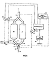
- Figure 6 corresponds to Figure 4 of the aforesaid U. S. Serial No. 648,381, and follows the same numbering sequence used therein.
- the regeneration operation is effected by the injection of fuel, e.g., diesel fuel, into the catalytic converter, for example, converter 18, along with sufficient air to enable combustion to occur . and physically burn the trapped carbon particles thereby converting the fuel and carbon to carbon dioxide and water.
- fuel e.g., diesel fuel
- converter 18 e.g., converter 18
- These effluent gases are combined along with the catalytically converted gases from the opposite converter 20 through a "Y" fitting 22 for exit through the tail pipe portion 12a.
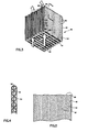
- FIG. 2 there is here shown in fragmentary cross section a catalytic converter 18 having a rectangular tubular housing 24 fitted at each end with a suitable end cap 26 and 28, respectively.
- the end caps 26 and 28 are geometrically configured to accept at their respective larger or wide-mouth extremities 30 and 32 the tubular housing 24 of rectangular or square cross section.
- the end caps 26 and 28 converge desirably to a circular nipple portion 34 and 36, respectively, dimensioned to accept a leg of the respective "Y" members 14 and 22.
- Attachment is conveniently by welding such as weldments 38 and 40.
- Attachment to the housing 24 is also conveniently by means of weldments such as weldments 42 and 44.
- the housing 24 is adapted to contain a metallic catalyst support member 46.
- the metallic substrate is a ferrous metal, preferably stainless steel.
- a fuel inlet 48 through which a readily vaporizable fuel, e.g., diesel fuel, may be introduced during the regeneration phase of operation. Also there is provided an inlet port 50 for the introduction of air into the system in an amount sufficient to promote combustion of the fuel and the carbon trapped within the metallic catalyst support member 46 useful in accordance with the present invention.
- a glow-plug (not shown) may be used in the end cap 26 to aid ignition of the fuel.
- the catalyst support member 46 is formed from a thin preferably stainless steel ribbon.
- This ribbon is generally from about 3 to about 12 inches in width and has a thickness of from 0.0015/0.003 inch and a yield strength of approximately 75,000 psi.
- the steel is provided with an aluminum coating, preferably by dipping, and the aluminum coated steel strip subjected to a calorizing process whereby at least a surface portion of the aluminum and the underlying iron become alloyed together much as described in the Patent to Downs 1,636,685.
- the strip is desirably annealed to overcome the brittleness of the calorizing process.
- the metal strip of the converter 20 is corrugated by passing the strip between toothed rollers adapted to depress portions of the metal out of the plain of the metal sheet to provide curved ribs or indentations uniformely along the length of the strip.
- the corrugations in the devices of the present invention are preferably laterally directed from side to side of the strip between the marginal edges thereof and do not form a straight line. Because of the configuration of the surfaces of the gears whereby the rolling teeth are canted on the outer surface thereof, and a series of alternating oppositely canted gears are mounted on a common shaft, there results a corrugation which is zig-zag in configuration to provide a herringbone pattern across the surface of the metal strip. Instead of straight line segments such as shown in Figure 3, the segments may be sinusoidal by using differently configured gear teeth.
- each corrugation is composed of a depression 48 and a peak such as the peak 50 and the peak 52. It will be noted that the peaks and valleys are in a zig-zag configuration between the parallel marginal edges 54 and 56.
- the entire unit is fan folded, i.e., a continuous strip is folded back and forth upon itself at uniformely spaced intervals.
- the intervals are determined by a series of transverse perforations extending through the metal strip and provide means for ingress and egress of gases between confronting layers.
- the layers 60 and 62 are in confronting relation, and gas may enter between layer 60 and 62 through the perforations 58.
- the gas may enter between confronting layers 62 and 64 by passing through the opening 66.
- a similar set of perforations 58 is provided along the fold line 68 to permit passage of gases from between layers 62 and 64. the gas flow patten is best shown in
- Gas moving along the path indicated by the arrow 70 enters the catalyst element 46 between the confronting layers 62 and 64. Gas having entered along arrow 70 exits the element 46 through a perforation 58 indicated by the arrow 74. Gas moving along the path indicated by the arrow 72 enters the catalytic element 46 through the perforations 58 and moves through the element 46 between confronting corrugated surfaces 60 and 62, and exits along the path indicated by the arrow 76.
- the zig-zag rolled configuration is believed to cause sufficient changes in the velocity and direction of the gas as it passes through between the folds, for example, between confronting faces 60 and 62, and confronting faces 62 and 64, to cause particulates carried in the gas stream to become adhered to the roughened catalytic surface and thus abstracted from the exhaust stream.
- the gases do not traverse the spaces by making sharp right angular turns and depositing carbon in "clefts" between adjacent or confronting layers of metal.
- the contact points between the confronting faces are relatively minor and thus, the structure of the present invention does not rely especially on the presence of "clefts" for the trapping of carbon particles.
- Catalytic converters 110 and 111 are of substantially the same contruction as that shown in Figure 1-5.
- the direction of exhaust gas flow is indicated by the arrows 113 and 114.
- Exhaust duct 140 is connected to a butterfly valve 112 which is connected to conduits 141 and 142 which conduct gas into the converters 110 and 111.
- the butterfly valve 112 has three positions: a neutral position as shown, allowing gas to flow freely into both converters, and two positions which force most of the gas to flow to only one of the converters 110 and 111.
- the dotted line 150 represents one of the latter positions in which most of the flow to converter 110 is cut off.
- the remaining valve position (not shown) closes off most of the flow to converter 111.
- the butterfly valve 112 thus comprises a diverter means which diverts the flow to one or the other of the catalytic converters 110 and 111.
- Diesel engine exhaust contains considerable amounts of oxygen which is useful to support combustion during the regeneration process. Of course, supplemental oxygen and/or fuel may be added as required.
- a pressure monitor 115 is connected to the input and output ends of the apparatus. Note that the pressure drop is measured at exhaust duct 140 and output duct 151, i.e., the pressure drop is measured across the entire system.
- a microprocessor 102 receives input representing the pressure drop as well as the engine speed from analog to digital converter 101. Microprocessor 102 stores data representing the change of pressure drop with engine speed.
- Microprocessor 102 is connected to temperature sensors 132 and 133 which control fuel valves 136 and 137, respectively. Microprocessor 102 is also connected to a timer and valve actuator means 103 which operates the butterfly valve 112.
- the microprocessor 102 When the microprocessor 102 senses an unacceptably high pressure drop, it causes the valve actuator means 103 to turn the butterfly valve 112 to one of its two non-neutral positions and then to the other such position. For example, the valve actuator means 103 will first actuate valve 112 such that flow of gas through converter 110 is substantially cut off. Valve 112 is held in this position for a few seconds by the actuator means 103 while the microprocessor 102 internally records and stores the sensed pressure drop. This pressure drop gives an indication of the extent to which converter 111 is filled with trapped particulates.
- Valve actuator means 103 when causes valve l12 to cut off most of the exhaust gas flow to converter 111 and microprocessor 102 then records and stores the pressure drop reading. The microprocessor 102 then selects the catalytic converter, either 110 or 111, that is in the greater need of regeneration.
- the microprocessor 102 When the microprocessor 102 selects a converter for regeneration, it emits an enabling signal to one of the temperature controllers 132 or 133 to cause fuel to be injected in a controlled manner into the converter selected for regeneration.
- microprocessor 102 While one of the converters 110 or 111 is undergoing regeneration, microprocessor 102 keeps a record of the elapsed time. After 5 minutes of regeneration, for example, the microprocessor 102 momentarily disables the temperature controller 132 or 133, as the case may be, and through the valve actuator means 103 turns the butterfly valve 112 momentarily to a neutral position. The pressure drop across the entire system is again measured. If the pressure drop is sufficiently low for the current engine speed, the regeneration is complete and the system returns to its original state, i.e., with the butterfly valve 112 in a neutral position and both temperature controllers 132 and 133 disabled. If the pressure drop is not low enough, the microprocessor 102 reactivates the temperature controller that was previously operative and regeneration continues. Thereafter, every minute the microprocessor 102 interrupts the regeneration process to determine whether regeneration may be terminated.
- the test for completeness of the regeneration process requires 1 to 2 seconds.
- the entire regeneration process may take from 5 to 10 minutes, or more. It is expected that for most of the period during which the engine is running, no regeneration is taking place and the butterfly valve 112 would therefore be in a neutral position most of the time.
- the length of the catalytic converter unit 18, 20 may range from 10 to 16 inches, and is preferably 12-14 inches in length.
- a single fan folded unit 46 may be used in each of the housings.
- a plurality of fan folded units 46 of shorter length than the axial length of housing 24 may be employed. However, this merely increases the cost without particular advantage in efficiency of operation.
- the metal may be cal orized as indicated above and then coated with a "wash coat" of aluminum oxide uniformly applied to the corrugated surface and carefully dried.
- This provides a strongly adherent base onto which catalytic metals such as palladium, platinum, rhodium, nickel, copper, or combinations of such catalysts may be applied by known means.
- the usual catalysts are platinum, and/or palladium, and/or rhodium.
- Numerous catalytic systems are available for use in accordance with the present invention. Reference may be had to the Patent to Oshima et al 3,873,472 for an all metal catalyst element for purifying exhaust gases.
- the patent to Brewer 3,867,313 also discloses another all metal high temperature resistant catalyst element provided by plating or depositing a noble metal comprising platinum and/or palladium onto a base material which comprises primarily aluminum, chromium and iron.
Landscapes
- Engineering & Computer Science (AREA)
- Chemical & Material Sciences (AREA)
- Chemical Kinetics & Catalysis (AREA)
- Combustion & Propulsion (AREA)
- General Engineering & Computer Science (AREA)
- Mechanical Engineering (AREA)
- Health & Medical Sciences (AREA)
- Toxicology (AREA)
- Environmental & Geological Engineering (AREA)
- Analytical Chemistry (AREA)
- General Chemical & Material Sciences (AREA)
- Oil, Petroleum & Natural Gas (AREA)
- Biomedical Technology (AREA)
- Organic Chemistry (AREA)
- Materials Engineering (AREA)
- Exhaust Gas After Treatment (AREA)
- Exhaust Gas Treatment By Means Of Catalyst (AREA)
- Processes For Solid Components From Exhaust (AREA)
Applications Claiming Priority (2)
| Application Number | Priority Date | Filing Date | Title |
|---|---|---|---|
| US796710 | 1985-11-12 | ||
| US06/796,710 US4725411A (en) | 1985-11-12 | 1985-11-12 | Device for physical and/or chemical treatment of fluids |
Publications (2)
| Publication Number | Publication Date |
|---|---|
| EP0222355A2 true EP0222355A2 (fr) | 1987-05-20 |
| EP0222355A3 EP0222355A3 (fr) | 1989-02-08 |
Family
ID=25168865
Family Applications (1)
| Application Number | Title | Priority Date | Filing Date |
|---|---|---|---|
| EP86115536A Withdrawn EP0222355A3 (fr) | 1985-11-12 | 1986-11-08 | Dispositif de traitement physique et/ou chimique de fluides |
Country Status (4)
| Country | Link |
|---|---|
| US (1) | US4725411A (fr) |
| EP (1) | EP0222355A3 (fr) |
| JP (1) | JPS62168915A (fr) |
| CA (1) | CA1270806A (fr) |
Cited By (8)
| Publication number | Priority date | Publication date | Assignee | Title |
|---|---|---|---|---|
| EP0284891A1 (fr) * | 1987-03-23 | 1988-10-05 | W.R. Grace & Co.-Conn. | Optimisation de l'empilage de feuille métallique pour convertisseurs catalytiques |
| EP0289817A1 (fr) * | 1987-04-18 | 1988-11-09 | Thyssen Edelstahlwerke AG | Elément nid d'abeilles pour la purification des gaz d'échappement de machines à combustion interne |
| EP0304762A1 (fr) * | 1987-08-26 | 1989-03-01 | W.R. Grace & Co.-Conn. | Filtre de particules |
| EP0405310A3 (en) * | 1989-06-24 | 1991-08-21 | Degussa Aktiengesellschaft | Process for regenerating soot filters of diesel engines |
| WO1994001661A1 (fr) * | 1992-07-14 | 1994-01-20 | Emitec Gesellschaft Für Emissionstechnologie Mbh | Corps metallique en nid d'abeilles compose de couches de tole entrelacees et son procede de fabrication |
| WO1997039227A1 (fr) * | 1996-04-17 | 1997-10-23 | Engelhard Corporation | Element metallique en nid d'abeilles |
| WO1998015354A1 (fr) * | 1996-10-10 | 1998-04-16 | Engelhard Corporation | Corps alveolaire de support pour des convertisseurs catalytiques et son procede de fabrication |
| CN106839184A (zh) * | 2017-02-20 | 2017-06-13 | 深圳埃鲨智能科技有限公司 | 一种用于新风净化设备的组合式电巢及新风治理器 |
Families Citing this family (34)
| Publication number | Priority date | Publication date | Assignee | Title |
|---|---|---|---|---|
| US4797137A (en) * | 1987-03-30 | 1989-01-10 | Sutton Energy Corporation | Apparatus for cleaning fossil fuel, such as coal and crude oil |
| US4823583A (en) * | 1987-06-11 | 1989-04-25 | W. R. Grace & Co.-Conn. | Particulate trap |
| US5211918A (en) * | 1987-12-22 | 1993-05-18 | Schwabische Huttenwerke | Catalytic converter for exhaust gases |
| US4942020A (en) * | 1988-06-27 | 1990-07-17 | W.R. Grace & Co.-Conn. | Converter for removing pollutants from a gas stream |
| EP0396650B2 (fr) * | 1988-09-02 | 1995-04-12 | GebràDer Sulzer Aktiengesellschaft | Dispositif de mise en uvre de reactions catalysees |
| US5202303A (en) * | 1989-02-24 | 1993-04-13 | W. R. Grace & Co.-Conn. | Combustion apparatus for high-temperature environment |
| US5346389A (en) * | 1989-02-24 | 1994-09-13 | W. R. Grace & Co.-Conn. | Combustion apparatus for high-temperature environment |
| US4928485A (en) * | 1989-06-06 | 1990-05-29 | W. R. Grace & Co.,-Conn. | Metallic core member for catalytic converter and catalytic converter containing same |
| DE4021495A1 (de) * | 1990-07-05 | 1992-01-09 | Schwaebische Huettenwerke Gmbh | Abgasfilter |
| DE4022937A1 (de) * | 1990-07-19 | 1992-01-23 | Schwaebische Huettenwerke Gmbh | Filter- oder katalysatorkoerper |
| DE4029749A1 (de) * | 1990-09-20 | 1992-03-26 | Schwaebische Huettenwerke Gmbh | Filter |
| DE4109227A1 (de) * | 1991-03-21 | 1992-09-24 | Schwaebische Huettenwerke Gmbh | Abgasfilter und/oder katalysator |
| DE4110285A1 (de) * | 1991-03-28 | 1992-10-01 | Schwaebische Huettenwerke Gmbh | Filter- oder katalysatorkoerper |
| US5171589A (en) * | 1991-05-31 | 1992-12-15 | Wm. Wrigley Jr. Company | Coated chewing gun products polished with colored wax and method of preparation |
| US5204067A (en) * | 1991-07-11 | 1993-04-20 | Schwaebische Huettenwerke Gmbh | Filter |
| DE4137105A1 (de) * | 1991-11-12 | 1993-05-13 | Schwaebische Huettenwerke Gmbh | Anordnung eines katalysators fuer die abgase eines verbrennungsmotors |
| US5328359A (en) * | 1992-05-19 | 1994-07-12 | W. R. Grace & Co.-Conn. | Ignition stage for a high temperature combustor |
| US6284201B1 (en) | 1993-02-10 | 2001-09-04 | Alfred Buck | Apparatus for the catalytic purification of flowing gases, in particular exhaust gases of internal combustion engines |
| US5427746A (en) * | 1994-03-08 | 1995-06-27 | W. R. Grace & Co.-Conn. | Flow modification devices for reducing emissions from thermal voc oxidizers |
| US5572866A (en) * | 1994-04-29 | 1996-11-12 | Environmental Thermal Oxidizers, Inc. | Pollution abatement incinerator system |
| JP2601999B2 (ja) * | 1994-07-29 | 1997-04-23 | インターナショナル・ビジネス・マシーンズ・コーポレイション | ディスクドライブ装置 |
| US5735158A (en) * | 1996-10-10 | 1998-04-07 | Engelhard Corporation | Method and apparatus for skew corrugating foil |
| WO2000030739A1 (fr) * | 1998-11-24 | 2000-06-02 | Clean Diesel Technologies, Inc. | Comburant particulaire catalyse servant a reduire les emissions particulaires d'un moteur diesel et procede associe |
| US6375700B1 (en) * | 2000-06-23 | 2002-04-23 | Nelson Industries, Inc. | Direct flow filter |
| EP1247558A1 (fr) * | 2001-04-07 | 2002-10-09 | 3M Innovative Properties Company | Filtre combiné pour filtrer des fluides |
| US6911061B2 (en) * | 2002-09-05 | 2005-06-28 | Nuclear Filter Technology | In-line HEPA filter |
| ITMI20030960A1 (it) * | 2003-05-13 | 2004-11-14 | Arturo Colamussi | Filtro di carta microporosa per particolato. |
| DE10356997A1 (de) * | 2003-12-03 | 2005-07-07 | Helmut Swars | Partikelfilter |
| US20060117743A1 (en) * | 2004-12-03 | 2006-06-08 | Helmut Swars | Regeneratable particle filter |
| DE102005038707A1 (de) * | 2005-08-15 | 2007-03-08 | Emitec Gesellschaft Für Emissionstechnologie Mbh | Verfahren und Vorrichtung zur Aufbereitung eines Abgases einer Verbrennungskraftmaschine |
| US7343736B2 (en) | 2006-02-27 | 2008-03-18 | Detroit Diesel Corporation | Flexible exhaust emission aftertreatment system for compression cycle diesel engines |
| CA2909943A1 (fr) * | 2013-04-25 | 2014-10-30 | Robert W. Ferguson | Dispositif de chauffage a combustible solide |
| WO2019194881A1 (fr) | 2018-04-05 | 2019-10-10 | Catalytic Combustion Corporation | Catalyseur en feuille métallique pour la commande d'émissions provenant de moteurs diesel |
| US20220323886A1 (en) * | 2021-04-08 | 2022-10-13 | Chevron U.S.A. Inc. | Filtration System and Method |
Family Cites Families (13)
| Publication number | Priority date | Publication date | Assignee | Title |
|---|---|---|---|---|
| US3362783A (en) * | 1963-12-23 | 1968-01-09 | Texaco Inc | Treatment of exhaust gases |
| US3561928A (en) * | 1966-10-31 | 1971-02-09 | Electro Isolier Ind Wahn | Gas purifying apparatus |
| DE2149989A1 (de) * | 1970-10-08 | 1972-05-31 | Mitsui Mining & Smelting Co | Verfahren und Vorrichtung zur Reinigung von Kohlenmonoxyd enthaltenden Abgasen sowie ein hierfuer verwendeter Katalysator |
| US3716344A (en) * | 1971-02-10 | 1973-02-13 | New Prod Corp | Internal combustion engine exhaust catalytic reactor |
| AT320088B (de) * | 1971-07-28 | 1975-01-27 | Braun Ag | Elektrostatisches Filter |
| SE385661B (sv) * | 1974-03-01 | 1976-07-19 | Lectrostatic Ab | Filteranordning av papp |
| JPS5698517A (en) * | 1980-01-09 | 1981-08-08 | Toyota Motor Corp | Apparatus for removing fine particles contained in exhaust gas of internal combustion engine |
| US4346557A (en) * | 1980-05-07 | 1982-08-31 | General Motors Corporation | Incineration-cleanable composite diesel exhaust filter and vehicle equipped therewith |
| DE3109609A1 (de) * | 1981-03-13 | 1982-09-23 | Kernforschungsanlage Jülich GmbH, 5170 Jülich | "schadstoff-filter fuer abgase" |
| US4455823A (en) * | 1982-10-20 | 1984-06-26 | General Motors Corporation | Diesel exhaust particulate trap with pleated filter |
| DE3341868A1 (de) * | 1983-11-19 | 1985-05-30 | Süddeutsche Kühlerfabrik Julius Fr. Behr GmbH & Co KG, 7000 Stuttgart | Matrix fuer einen katalytischen reaktor |
| US4597262A (en) * | 1984-09-07 | 1986-07-01 | Retallick William B | Catalytic converter for a diesel engine |
| US4576800A (en) * | 1984-09-13 | 1986-03-18 | Camet, Inc. | Catalytic converter for an automobile |
-
1985
- 1985-11-12 US US06/796,710 patent/US4725411A/en not_active Expired - Fee Related
-
1986
- 1986-11-06 CA CA000522307A patent/CA1270806A/fr not_active Expired - Lifetime
- 1986-11-08 EP EP86115536A patent/EP0222355A3/fr not_active Withdrawn
- 1986-11-12 JP JP61269489A patent/JPS62168915A/ja active Pending
Cited By (11)
| Publication number | Priority date | Publication date | Assignee | Title |
|---|---|---|---|---|
| EP0284891A1 (fr) * | 1987-03-23 | 1988-10-05 | W.R. Grace & Co.-Conn. | Optimisation de l'empilage de feuille métallique pour convertisseurs catalytiques |
| EP0289817A1 (fr) * | 1987-04-18 | 1988-11-09 | Thyssen Edelstahlwerke AG | Elément nid d'abeilles pour la purification des gaz d'échappement de machines à combustion interne |
| EP0304762A1 (fr) * | 1987-08-26 | 1989-03-01 | W.R. Grace & Co.-Conn. | Filtre de particules |
| EP0405310A3 (en) * | 1989-06-24 | 1991-08-21 | Degussa Aktiengesellschaft | Process for regenerating soot filters of diesel engines |
| WO1994001661A1 (fr) * | 1992-07-14 | 1994-01-20 | Emitec Gesellschaft Für Emissionstechnologie Mbh | Corps metallique en nid d'abeilles compose de couches de tole entrelacees et son procede de fabrication |
| US5464679A (en) * | 1992-07-14 | 1995-11-07 | Emitec Gesellschaft Fuer Emissionstechnologie Mbh | Metal honeycomb body of intertwined sheet-metal layers, and method for its production |
| US5608968A (en) * | 1992-07-14 | 1997-03-11 | Emitec Gesellschaft Fuer Emissionstechnologie Mbh | Method of making a metal honeycomb body of intertwined sheet-metal layers |
| US5785931A (en) * | 1992-07-14 | 1998-07-28 | Emitec Gesellschaft Fuer Emissions-Technologie Mbh | Metal honeycomb body of intertwined sheet-metal layers, and method for its production |
| WO1997039227A1 (fr) * | 1996-04-17 | 1997-10-23 | Engelhard Corporation | Element metallique en nid d'abeilles |
| WO1998015354A1 (fr) * | 1996-10-10 | 1998-04-16 | Engelhard Corporation | Corps alveolaire de support pour des convertisseurs catalytiques et son procede de fabrication |
| CN106839184A (zh) * | 2017-02-20 | 2017-06-13 | 深圳埃鲨智能科技有限公司 | 一种用于新风净化设备的组合式电巢及新风治理器 |
Also Published As
| Publication number | Publication date |
|---|---|
| US4725411A (en) | 1988-02-16 |
| CA1270806A (fr) | 1990-06-26 |
| JPS62168915A (ja) | 1987-07-25 |
| EP0222355A3 (fr) | 1989-02-08 |
Similar Documents
| Publication | Publication Date | Title |
|---|---|---|
| US4725411A (en) | Device for physical and/or chemical treatment of fluids | |
| Kummer | Catalysts for automobile emission control | |
| US6314722B1 (en) | Method and apparatus for emission control | |
| US4672809A (en) | Catalytic converter for a diesel engine | |
| US20060080953A1 (en) | Method for regenerating a particle trap and exhaust system | |
| EP0789135B1 (fr) | Purificateur de gaz d'échappement | |
| KR101030145B1 (ko) | 코팅된 섬유층을 구비한 입자 트랩 | |
| JP3917267B2 (ja) | 排ガス浄化装置 | |
| US8475753B2 (en) | Exhaust-gas aftertreatment system with catalytically active wall-flow filter with storage function upstream of catalytic converter with identical storage function | |
| US4597262A (en) | Catalytic converter for a diesel engine | |
| US20040013580A1 (en) | Open filter body with improved flow properties | |
| US20060021331A1 (en) | Pre-combustors for internal combustion engines and systems and methods therefor | |
| EP1350933B1 (fr) | Dispositif pour la réduction des paticules de charbon | |
| US20080274020A1 (en) | Carrier for exhaust-gas purification and exhaust-gas purifier having the carrier | |
| US7347042B2 (en) | Exhaust gas filter and method for cleaning an exhaust gas | |
| JP2005535438A (ja) | リーンバーンエンジン用の排気機構 | |
| JP4448517B2 (ja) | 測定センサを有する被覆されたハニカム体 | |
| JP4035578B2 (ja) | ディーゼル・エンジン用パーティキュレート・フィルタ | |
| JP3321763B2 (ja) | エンジンの排気ガス処理装置 | |
| KR20110062625A (ko) | 질소 산화물 저감 촉매 및 이를 이용한 배기 장치 | |
| Ganesh et al. | Design and Fabrication of Two-Wheeler Silencer Using Catalytic Convertor | |
| Diwakar et al. | Design of the Electronically Aided Catalytic-Converter for ATV | |
| CN205001032U (zh) | 用于废气的净化器总成 | |
| KR20080097923A (ko) | 배기가스 정화용 담체 구조 | |
| JP2005256634A (ja) | 排気ガス浄化システム |
Legal Events
| Date | Code | Title | Description |
|---|---|---|---|
| PUAI | Public reference made under article 153(3) epc to a published international application that has entered the european phase |
Free format text: ORIGINAL CODE: 0009012 |
|
| AK | Designated contracting states |
Kind code of ref document: A2 Designated state(s): AT BE CH DE ES FR GB GR IT LI LU NL SE |
|
| RAP1 | Party data changed (applicant data changed or rights of an application transferred) |
Owner name: W.R. GRACE & CO. |
|
| RIN1 | Information on inventor provided before grant (corrected) |
Inventor name: CORNELISON, RICHARD C. |
|
| PUAL | Search report despatched |
Free format text: ORIGINAL CODE: 0009013 |
|
| AK | Designated contracting states |
Kind code of ref document: A3 Designated state(s): AT BE CH DE ES FR GB GR IT LI LU NL SE |
|
| STAA | Information on the status of an ep patent application or granted ep patent |
Free format text: STATUS: THE APPLICATION IS DEEMED TO BE WITHDRAWN |
|
| 18D | Application deemed to be withdrawn |
Effective date: 19890531 |
|
| RIN1 | Information on inventor provided before grant (corrected) |
Inventor name: CORNELISON, RICHARD C. |