EP0222430A1 - Vorrichtung zum Antrieb der Schlauchtrommel von automatischen Bewässerungseinrichtungen, im allgemeinen in Fortbewegungsschritten von einstellbarem Ausmass - Google Patents
Vorrichtung zum Antrieb der Schlauchtrommel von automatischen Bewässerungseinrichtungen, im allgemeinen in Fortbewegungsschritten von einstellbarem Ausmass Download PDFInfo
- Publication number
- EP0222430A1 EP0222430A1 EP86201772A EP86201772A EP0222430A1 EP 0222430 A1 EP0222430 A1 EP 0222430A1 EP 86201772 A EP86201772 A EP 86201772A EP 86201772 A EP86201772 A EP 86201772A EP 0222430 A1 EP0222430 A1 EP 0222430A1
- Authority
- EP
- European Patent Office
- Prior art keywords
- connecting rod
- drum
- crank
- sprocket
- pin
- Prior art date
- Legal status (The legal status is an assumption and is not a legal conclusion. Google has not performed a legal analysis and makes no representation as to the accuracy of the status listed.)
- Granted
Links
- 238000004804 winding Methods 0.000 title claims abstract description 15
- 230000002262 irrigation Effects 0.000 title claims abstract description 9
- 238000003973 irrigation Methods 0.000 title claims abstract description 9
- 239000003621 irrigation water Substances 0.000 claims abstract description 5
- XLYOFNOQVPJJNP-UHFFFAOYSA-N water Substances O XLYOFNOQVPJJNP-UHFFFAOYSA-N 0.000 claims description 4
- 239000007787 solid Substances 0.000 claims description 3
- 230000005540 biological transmission Effects 0.000 description 4
- 230000002159 abnormal effect Effects 0.000 description 2
- 230000007246 mechanism Effects 0.000 description 2
- 230000010355 oscillation Effects 0.000 description 2
- 230000003534 oscillatory effect Effects 0.000 description 1
- 238000005086 pumping Methods 0.000 description 1
- 230000003019 stabilising effect Effects 0.000 description 1
Images

Classifications
-
- A—HUMAN NECESSITIES
- A01—AGRICULTURE; FORESTRY; ANIMAL HUSBANDRY; HUNTING; TRAPPING; FISHING
- A01G—HORTICULTURE; CULTIVATION OF VEGETABLES, FLOWERS, RICE, FRUIT, VINES, HOPS OR SEAWEED; FORESTRY; WATERING
- A01G25/00—Watering gardens, fields, sports grounds or the like
- A01G25/09—Watering arrangements making use of movable installations on wheels or the like
- A01G25/095—Watering arrangements making use of movable installations on wheels or the like winch-driven
-
- Y—GENERAL TAGGING OF NEW TECHNOLOGICAL DEVELOPMENTS; GENERAL TAGGING OF CROSS-SECTIONAL TECHNOLOGIES SPANNING OVER SEVERAL SECTIONS OF THE IPC; TECHNICAL SUBJECTS COVERED BY FORMER USPC CROSS-REFERENCE ART COLLECTIONS [XRACs] AND DIGESTS
- Y02—TECHNOLOGIES OR APPLICATIONS FOR MITIGATION OR ADAPTATION AGAINST CLIMATE CHANGE
- Y02A—TECHNOLOGIES FOR ADAPTATION TO CLIMATE CHANGE
- Y02A40/00—Adaptation technologies in agriculture, forestry, livestock or agroalimentary production
- Y02A40/10—Adaptation technologies in agriculture, forestry, livestock or agroalimentary production in agriculture
- Y02A40/22—Improving land use; Improving water use or availability; Controlling erosion
Definitions
- This patent relates to a unit of small overall size by which the hose rewinding speed in automatic irrigation sprinklers in general can be kept constant whatever the hose winding diameter, and can be adjusted as required.
- automatic sprinklers which are able to automatically move from one end to the other of a strip of ground.
- automatic sprinklers comprising a trolley on which a horizontal drum is rotatably mounted and carries, wound about it in several superposed layers, a hose having its free end connected to a sprinkler device disposed on a skid.
- automatic sprinklers are known provided with a turbine through which the water flows before entering the hose, its impeller transmitting motion to the drum by way of a transmission comprising variable diameter pulleys, the turbine speed being adjusted by means of a by-pass pipe.
- Known automatic sprinklers have however drawbacks due to the cost of the turbine unit or hydraulic motor used, and the excessive overall size and weight of the entire transmission system, which usually occupies the whole of one side of the trolley.
- the present patent provides and protects a drum rotation device which, within the framework of a simple and economical structure of small overall size, eminently solves the stated problems.
- said device comprises a turbine driven by the actual irrigation water and having on its shaft a first crank to which there is connected a first connecting rod, the big end of which is compelled to move reciprocatingly along a substantially rectilinear path of variable direction, and is itself connected to the big end of a second connecting rod connected to a second crank which is longer than the first crank and which by way of a free-wheel device drives a sprocket from which the drum drive motion derives, there being provided means sensitive to the winding diameter of the hose on the drum which are arranged to orientate the direction of said substantially rectilinear path from a direction close to the axis of said second connecting rod to a substantially orthogonal direction, and means for transmitting motion from said sprocket to the drum shaft and comprising engagement and disengagement means.
- all the aforesaid mechanisms are housed in a casing of small overall size, to be removably fixed on to the sprinkler trolley, the turbine discharge being coaxial with the drum shaft.
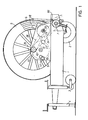
- FIG. 1 shows a normal trolley pertaining to a likewise normal automatic irrigation sprinkler, of which the sprinkler skid is not shown.
- the type of trolley shown must in no way be considered as limiting the extent of the invention, as it is suitable for application to any type of automatic sprinkler.
- Said trolley comprises a frame 1 mounted on two rear wheels 2 and on a front height-adjustable swivel wheel 3, in front of which there is an extendable stabilising foot 4.
- a hose-winding drum 5 On the frame 1 there is rotatably mounted, with its transverse axis horizontal, a hose-winding drum 5 on which a hose 6 is wound in several superposed helical layers and passes lowerly about a normal hose guiding device 7, its free end then being connected to a sprinkler mounted on a skid, not shown.
- a sprinkler mounted on a skid not shown.
- the skid On commencing irrigation the skid is dragged to the end of the area to be irrigated, with simultaneous unwinding of the hose 6 which then becomes rewound by the drum 5 under the control of the device according to the invention.
- a normal roller feeler 8 which is placed in contact with the outer layer of hose 6 wound on the drum 5.
- a casing 9 which is removably fixed to the frame 1.
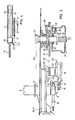
- the housing 10 of a radial-bladed impeller 11 is fixed in the front end of the casing 9, into which the irrigation water is fed through an oblique inlet port 12. After travelling through an arc of between 45 and 175 degrees, as can be better seen in Figure 3, said water emerges from a rear discharge port 13 to enter the hose 6, said discharge port 13 being coaxial with one of the lateral supports for the drum 5.
- the inlet port 12 is intended for connection to a convenient pumping unit.
- the shaft of the impeller 11, indicated by 14 in Figures 2 and 3, emerges from the housing 10, where it comprises a first crank 15 on which a first connecting rod 16 is pivotally mounted.
- a link rod 17 and a second connecting rod 18 are pivoted to the big end of said first connecting rod 16.
- the link rod 17 is connected to the top of a rocker lever 19 which is idly mounted on the shaft 14 of the impeller 11, the second connecting rod 18 being connected to a second crank 20 longer than the crank 15.
- the crank 20 is connected to the end of a shaft 21 (Figure 2) by way of a free wheel (not shown), the shaft 21 being rotatably mounted on a support 22 ( Figure 3) by way of a second free wheel, also not shown.
- a sprocket 23 which is connected by a chain transmission 24 to a sprocket 25 idly mounted on a splined shaft 26. It is apparent that because of the different length of the cranks, the rotary motion of the first is transformed into oscillatory motion of the second, this latter motion by virtue of the free wheels being transformed into a stepwise drive motion for the shaft 21. Said gear members 23, 25 provide an initial step-down of said stepwise motion.
- the splined end of said shaft 26 faces the corresponding side of the trolley 1, where it is embraced by a rotatable hollow selection member 27 arranged to torsionally engage the sprocket 25 with, and disengage it from, said shaft 26.
- the engagement/disengagement between the sprocket 25 and shaft 26 takes place as follows.
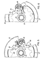
- an eccentric pin 28 is idly mounted on the said sprocket 25.
- the transverse contour of the pin 28 is partly superposed on the marginal edge of a disc 29 disposed in proximity to the sprocket 25 and keyed on the splined shaft 26.
- Said disc 29 is provided with a circumferential series of equidistant semicircular notches 30 having a diameter practically equal to the diameter of the pin 28.
- the pin 28 is provided with a transverse slot 31 in which the end of said dics 29 slides freely when this slot is disposed tangentially to this latter (see Figure 5), with simultaneous disconnection of the transmission between the disc 29 and sprocket 25.
- an adjustable brake is associated with the disc 29 to prevent it undergoing unwanted rotation.
- the second free wheel nominated heretofore with reference to the shaft 21 is also provided for the same purpose.
- a sprocket 37 which by way of a chain 38 drives a sprocket 39 fixed coaxially to the side of the drum 5.
- the said drum 5 comprises a second sprocket 40 which drives the hose guiding device 7 by way of a chain 41.
- Said means comprise a tube 42 hinged at 43 to the feeler 8 and slidingly carrying a rotatable rod 44 provided at the end closer to the feeler 8 with an adjustment knob 45.
- a rotatable rod 44 At the other end of the rod 44 there is an enlarged portion 46 from which a threaded stem 47 extends and engages in an idle pin 48 provided at the lower end of the rocker lever 19.
- tension springs 49, 50 there are also provided two tension springs 49, 50, the first 49 connecting the rocker lever 19 to the tube 42, and the second 50 engaged with this latter and with the casing 9 in order to ensure contact between the feeler 8 and the hose 6 wound on the drum 5.
- the enlarged portion 46 is kept in the position shown in Figure 2 by a pawl 51 which penetrates into the tube 42 through a convenient aperture ( Figure 4). Said pawl 51 is pivoted at 52 to the tube and is kept in its locking position by a tension spring 53.
- the hose is unwound, the tube 42 re-enters the casing 9, and the operator inserts the rod 44 to engage the enlarged portion 56 with the pawl 51.
Landscapes
- Engineering & Computer Science (AREA)
- Water Supply & Treatment (AREA)
- Life Sciences & Earth Sciences (AREA)
- Environmental Sciences (AREA)
- Storing, Repeated Paying-Out, And Re-Storing Of Elongated Articles (AREA)
- Catching Or Destruction (AREA)
- Details Or Accessories Of Spraying Plant Or Apparatus (AREA)
- Examining Or Testing Airtightness (AREA)
- Medicines That Contain Protein Lipid Enzymes And Other Medicines (AREA)
- Preparation Of Compounds By Using Micro-Organisms (AREA)
Priority Applications (1)
| Application Number | Priority Date | Filing Date | Title |
|---|---|---|---|
| AT86201772T ATE59934T1 (de) | 1985-11-08 | 1986-10-14 | Vorrichtung zum antrieb der schlauchtrommel von automatischen bewaesserungseinrichtungen, im allgemeinen in fortbewegungsschritten von einstellbarem ausmass. |
Applications Claiming Priority (2)
| Application Number | Priority Date | Filing Date | Title |
|---|---|---|---|
| IT4686485 | 1985-11-08 | ||
| IT46864/85A IT1187806B (it) | 1985-11-08 | 1985-11-08 | Dispositivo per il trascinamento a scatti di ampiezza registrabile del tamburo avvolgitubo degli irrigatori automatici in genere |
Publications (2)
| Publication Number | Publication Date |
|---|---|
| EP0222430A1 true EP0222430A1 (de) | 1987-05-20 |
| EP0222430B1 EP0222430B1 (de) | 1991-01-16 |
Family
ID=11259903
Family Applications (1)
| Application Number | Title | Priority Date | Filing Date |
|---|---|---|---|
| EP86201772A Expired - Lifetime EP0222430B1 (de) | 1985-11-08 | 1986-10-14 | Vorrichtung zum Antrieb der Schlauchtrommel von automatischen Bewässerungseinrichtungen, im allgemeinen in Fortbewegungsschritten von einstellbarem Ausmass |
Country Status (5)
| Country | Link |
|---|---|
| EP (1) | EP0222430B1 (de) |
| AT (1) | ATE59934T1 (de) |
| DE (1) | DE3676951D1 (de) |
| IT (1) | IT1187806B (de) |
| PT (1) | PT83709B (de) |
Cited By (2)
| Publication number | Priority date | Publication date | Assignee | Title |
|---|---|---|---|---|
| CN113800337A (zh) * | 2021-10-08 | 2021-12-17 | 江苏徐工工程机械研究院有限公司 | 一种排水抢险车用可翻转水带卷盘架及排水抢险车 |
| CN116349472A (zh) * | 2023-05-08 | 2023-06-30 | 浙江环创科技有限公司 | 一种水肥一体化智能喷灌装置 |
Families Citing this family (1)
| Publication number | Priority date | Publication date | Assignee | Title |
|---|---|---|---|---|
| CN109122235B (zh) * | 2016-03-17 | 2020-07-28 | 江苏华源节水股份有限公司 | 一种智能反馈式水涡轮驱动装置 |
Citations (3)
| Publication number | Priority date | Publication date | Assignee | Title |
|---|---|---|---|---|
| US4182203A (en) * | 1978-02-24 | 1980-01-08 | Drury Marcus D | Continuously variable mechanical transmission |
| AT359766B (de) * | 1979-07-13 | 1980-11-25 | Minichmayr Wilhelm | Getriebe fuer eine berieselungsvorrichtung |
| AT371662B (de) * | 1979-12-19 | 1983-07-25 | Waldhauser Maschf | Turbine vorzugsweise fuer beregnungsgeraete |
-
1985
- 1985-11-08 IT IT46864/85A patent/IT1187806B/it active
-
1986
- 1986-10-14 DE DE8686201772T patent/DE3676951D1/de not_active Expired - Fee Related
- 1986-10-14 AT AT86201772T patent/ATE59934T1/de not_active IP Right Cessation
- 1986-10-14 EP EP86201772A patent/EP0222430B1/de not_active Expired - Lifetime
- 1986-11-07 PT PT83709A patent/PT83709B/pt not_active IP Right Cessation
Patent Citations (3)
| Publication number | Priority date | Publication date | Assignee | Title |
|---|---|---|---|---|
| US4182203A (en) * | 1978-02-24 | 1980-01-08 | Drury Marcus D | Continuously variable mechanical transmission |
| AT359766B (de) * | 1979-07-13 | 1980-11-25 | Minichmayr Wilhelm | Getriebe fuer eine berieselungsvorrichtung |
| AT371662B (de) * | 1979-12-19 | 1983-07-25 | Waldhauser Maschf | Turbine vorzugsweise fuer beregnungsgeraete |
Non-Patent Citations (1)
| Title |
|---|
| LANDTECHNIK, vol. 38, no. 9, September 1983, page 359, Lehrte; * |
Cited By (3)
| Publication number | Priority date | Publication date | Assignee | Title |
|---|---|---|---|---|
| CN113800337A (zh) * | 2021-10-08 | 2021-12-17 | 江苏徐工工程机械研究院有限公司 | 一种排水抢险车用可翻转水带卷盘架及排水抢险车 |
| CN116349472A (zh) * | 2023-05-08 | 2023-06-30 | 浙江环创科技有限公司 | 一种水肥一体化智能喷灌装置 |
| CN116349472B (zh) * | 2023-05-08 | 2023-09-15 | 浙江环创科技有限公司 | 一种水肥一体化智能喷灌装置 |
Also Published As
| Publication number | Publication date |
|---|---|
| PT83709B (pt) | 1991-02-08 |
| EP0222430B1 (de) | 1991-01-16 |
| IT1187806B (it) | 1987-12-23 |
| DE3676951D1 (de) | 1991-02-21 |
| PT83709A (pt) | 1986-12-01 |
| IT8546864A0 (it) | 1985-11-08 |
| IT8546864A1 (it) | 1987-05-08 |
| ATE59934T1 (de) | 1991-02-15 |
Similar Documents
| Publication | Publication Date | Title |
|---|---|---|
| US4543982A (en) | Automatic rewinding water hose reel | |
| US4813627A (en) | Rewindable hose reel | |
| US4552315A (en) | Rolled web dispenser | |
| US4513772A (en) | Automatic hose reel | |
| US8424791B2 (en) | Reel assembly | |
| US4285127A (en) | Apparatus for trimming plants | |
| US4426780A (en) | Line metering apparatus | |
| CN101816241A (zh) | 植物切割装置 | |
| US3684178A (en) | Traveling agricultural sprinkler | |
| EP0222430B1 (de) | Vorrichtung zum Antrieb der Schlauchtrommel von automatischen Bewässerungseinrichtungen, im allgemeinen in Fortbewegungsschritten von einstellbarem Ausmass | |
| US2683056A (en) | Traveling lawn sprinkler | |
| US10589958B2 (en) | Hose reel assembly | |
| US3477643A (en) | Sprinkler irrigation device with improved hose handling means and method of deploying the same preparatory to a sprinkler irrigation cycle | |
| US2247004A (en) | Driving mechanism for flexible shafts | |
| US6802336B1 (en) | Hose reel apparatus | |
| US20140261766A1 (en) | Hose reel assembly | |
| CA2983974A1 (en) | Hose reel brake apparatus | |
| US5236131A (en) | Vehicle for distributing liquid over the ground | |
| US4538761A (en) | Windup-hose irrigating apparatus | |
| CA1255915A (en) | Fiber optic cable | |
| JPH0254046B2 (de) | ||
| US1891854A (en) | Combined lawn-mower and sprinkler | |
| PT83710B (pt) | Aspersor de rega autopropulsionado para relva | |
| US5346158A (en) | Casting reel with automatic drag and casting mechanism | |
| EP0188308B1 (de) | Flüssigkeitsverteilervorrichtung |
Legal Events
| Date | Code | Title | Description |
|---|---|---|---|
| PUAI | Public reference made under article 153(3) epc to a published international application that has entered the european phase |
Free format text: ORIGINAL CODE: 0009012 |
|
| AK | Designated contracting states |
Kind code of ref document: A1 Designated state(s): AT BE CH DE ES FR GB GR IT LI LU NL SE |
|
| RAP1 | Party data changed (applicant data changed or rights of an application transferred) |
Owner name: IRRIGAZIONI FERBO DI BOMBARDA FERDINANDO S.P.A. |
|
| 17P | Request for examination filed |
Effective date: 19871113 |
|
| 17Q | First examination report despatched |
Effective date: 19890417 |
|
| RAP1 | Party data changed (applicant data changed or rights of an application transferred) |
Owner name: FERBO COFADSI S.R.L. |
|
| GRAA | (expected) grant |
Free format text: ORIGINAL CODE: 0009210 |
|
| AK | Designated contracting states |
Kind code of ref document: B1 Designated state(s): AT BE CH DE ES FR GB GR IT LI LU NL SE |
|
| PG25 | Lapsed in a contracting state [announced via postgrant information from national office to epo] |
Ref country code: IT Free format text: LAPSE BECAUSE OF FAILURE TO SUBMIT A TRANSLATION OF THE DESCRIPTION OR TO PAY THE FEE WITHIN THE PRE;WARNING: LAPSES OF ITALIAN PATENTS WITH EFFECTIVE DATE BEFORE 2007 MAY HAVE OCCURRED AT ANY TIME BEFORE 2007. THE CORRECT EFFECTIVE DATE MAY BE DIFFERENT FROM THE ONE RECORDED.SCRIBED TIME-LIMIT Effective date: 19910116 Ref country code: NL Effective date: 19910116 Ref country code: LI Effective date: 19910116 Ref country code: SE Effective date: 19910116 Ref country code: GR Free format text: LAPSE BECAUSE OF FAILURE TO SUBMIT A TRANSLATION OF THE DESCRIPTION OR TO PAY THE FEE WITHIN THE PRESCRIBED TIME-LIMIT Effective date: 19910116 Ref country code: CH Effective date: 19910116 Ref country code: BE Effective date: 19910116 Ref country code: AT Effective date: 19910116 |
|
| REF | Corresponds to: |
Ref document number: 59934 Country of ref document: AT Date of ref document: 19910215 Kind code of ref document: T |
|
| REF | Corresponds to: |
Ref document number: 3676951 Country of ref document: DE Date of ref document: 19910221 |
|
| ET | Fr: translation filed | ||
| PG25 | Lapsed in a contracting state [announced via postgrant information from national office to epo] |
Ref country code: ES Free format text: LAPSE BECAUSE OF FAILURE TO SUBMIT A TRANSLATION OF THE DESCRIPTION OR TO PAY THE FEE WITHIN THE PRESCRIBED TIME-LIMIT Effective date: 19910427 |
|
| REG | Reference to a national code |
Ref country code: CH Ref legal event code: PL |
|
| NLV1 | Nl: lapsed or annulled due to failure to fulfill the requirements of art. 29p and 29m of the patents act | ||
| PG25 | Lapsed in a contracting state [announced via postgrant information from national office to epo] |
Ref country code: GB Effective date: 19911014 |
|
| PG25 | Lapsed in a contracting state [announced via postgrant information from national office to epo] |
Ref country code: LU Free format text: LAPSE BECAUSE OF NON-PAYMENT OF DUE FEES Effective date: 19911031 |
|
| PLBE | No opposition filed within time limit |
Free format text: ORIGINAL CODE: 0009261 |
|
| STAA | Information on the status of an ep patent application or granted ep patent |
Free format text: STATUS: NO OPPOSITION FILED WITHIN TIME LIMIT |
|
| 26N | No opposition filed | ||
| GBPC | Gb: european patent ceased through non-payment of renewal fee | ||
| PG25 | Lapsed in a contracting state [announced via postgrant information from national office to epo] |
Ref country code: DE Effective date: 19920701 |
|
| PGFP | Annual fee paid to national office [announced via postgrant information from national office to epo] |
Ref country code: FR Payment date: 19981019 Year of fee payment: 13 |
|
| PG25 | Lapsed in a contracting state [announced via postgrant information from national office to epo] |
Ref country code: FR Free format text: LAPSE BECAUSE OF NON-PAYMENT OF DUE FEES Effective date: 20000630 |
|
| REG | Reference to a national code |
Ref country code: FR Ref legal event code: ST |