EP0222440A1 - Bodenbearbeitungsgerät - Google Patents
Bodenbearbeitungsgerät Download PDFInfo
- Publication number
- EP0222440A1 EP0222440A1 EP86201860A EP86201860A EP0222440A1 EP 0222440 A1 EP0222440 A1 EP 0222440A1 EP 86201860 A EP86201860 A EP 86201860A EP 86201860 A EP86201860 A EP 86201860A EP 0222440 A1 EP0222440 A1 EP 0222440A1
- Authority
- EP
- European Patent Office
- Prior art keywords
- adjusting member
- soil cultivating
- roller
- relative
- cultivating machine
- Prior art date
- Legal status (The legal status is an assumption and is not a legal conclusion. Google has not performed a legal analysis and makes no representation as to the accuracy of the status listed.)
- Granted
Links
- 239000002689 soil Substances 0.000 title claims abstract description 41
- 238000010276 construction Methods 0.000 claims abstract description 23
- 230000008878 coupling Effects 0.000 description 5
- 238000010168 coupling process Methods 0.000 description 5
- 238000005859 coupling reaction Methods 0.000 description 5
- 230000005540 biological transmission Effects 0.000 description 2
- 230000000694 effects Effects 0.000 description 1
- 230000000717 retained effect Effects 0.000 description 1
- 125000006850 spacer group Chemical group 0.000 description 1
Images



Classifications
-
- A—HUMAN NECESSITIES
- A01—AGRICULTURE; FORESTRY; ANIMAL HUSBANDRY; HUNTING; TRAPPING; FISHING
- A01B—SOIL WORKING IN AGRICULTURE OR FORESTRY; PARTS, DETAILS, OR ACCESSORIES OF AGRICULTURAL MACHINES OR IMPLEMENTS, IN GENERAL
- A01B49/00—Combined machines
- A01B49/02—Combined machines with two or more soil-working tools of different kind
- A01B49/022—Combined machines with two or more soil-working tools of different kind at least one tool being actively driven
- A01B49/025—Combined machines with two or more soil-working tools of different kind at least one tool being actively driven about a substantially vertical axis
Definitions
- the invention relates to a soil cultivating machine comprising a frame in which a plurality of soil cultivating members are supported, and a roller located behind the soil cultivating members and supported by a carrier construction, which carrier construction is movable in height relative to the frame, an adjusting member being disposed between the carrier construction and the upper side of a trestle located on the frame, said adjusting member being operable from the tractor and an indicator mechanism being present, with the aid of which the adjusted position of the roller can be checked from the tractor.
- the indicator mechanism constitutes part of the adjusting member.
- a compact unit incorporating the adjusting member and the indicator mechanism is obtained, which can be easily attached and detached, and be used with several other machines.
- a further aspect of the invention relates to a soil cultivating machine comprising a frame in which a plurality of soil cultivating members are supported, and a roller located behind the soil cultivating members and supported by a carrier construction, which carrier construction is movable in height relative to the frame, an adjusting member being disposed between the carrier construction and the upper side of a trestle located on the frame, the distance between the attachment points of said adjusting member being changeable through a predefined distance and, during operation, the frame being movable in height through a predetermined distance relative to the roller.
- the arrangement shown in the drawings relates to a soil cultivating machine, more specifically for the preparation of seed bed.
- the machine comprises a box-like frame portion 1 which extends transversely to the direction of operative travel A and in which the upwardly directed, preferably at least substantially vertical, shafts 2 of soil cultivating members 3 are supported equidistantly at preferably 25 cms.
- Each of the soil cultivating members 3 includes an at least substantially horizontal carrier 4 which is disposed under the box-like portion 1 on a shaft 2 and has at each end a downwardly extending soil cultivating portion 5 constituted by a tine.
- the ends of the box-like frame portion 1 are each closed by rectangular plates 6.
- the upper sides of the rectangular plates 6 are covered by downwardly bent portions of a cover plate (6A) disposed at the upper side of the frame portion 1 ( Figure 2).
- An upwardly extending support 7 ' is arranged above each of the plates 6.
- Each support 7 includes an at least substantially horizontally extending transverse shaft 8.
- An arm 9, which extends rearwardly along a support 7, is provided freely pivotably around the transverse shaft 8, said arm having a widened portion at its rear side.
- the widened portions of the two arms 9 are interconnected by means of two tubular transverse beams 10 and 11.
- the foremost transverse beam 11 is in a higher position than the rearmost one.
- the transverse beams 10 and 11 are connected to an upwardly directed plate 12, which extends at least substantially parallel to a vertical plane in the direction of operative travel A.
- the plate 12 is arranged pivotally near the front side of the box-like frame portion 1 by means of an upright lug and a transverse shaft located in line with the transverse shafts 8 for the arms 9.
- the widened portions of the arms 9 are each provided with a downwardly and slightly forwardly extending support 13 in the form of a plate.
- a roller 16 is arranged freely rotatably between the supports 13 by means of bearings accomodated in a bearing housing 14 and a shaft 15.
- the roller 16 is in the form of a packer roller, while scrapers 18 are present that reach to between the crowns of cams 17.
- the scrapers 18 each are connected to a carrier 10A by means of an arm 19 which is directed obliquely upwardly and rearwardly.
- the carrier 10A is located behind the transverse beam 10, so that there is sufficient space for the extra large packer roller preferably having a diameter of approximately 50 cms.
- the carrier 10A is mounted between the transverse beams 10 and 11 by means of supports 11A and clamping means 12A.
- the supports 11A can be adjusted by means of a slot 13A and bolts 14A, so that the appropriate position relative to the cylindrical portion of the packer roller can be set.
- the specific arrangement of the carrier 10A ensures that, in spite of the use of a packer roller having a large diameter, the whole assembly remains compact, so that the combination with a seed drill or a planter arrangement is not impeded or negatively affected.
- the supports 11A are situated between the roller 16 and the transverse beams 10 and 11, their exact location being between the crown of cams 17. If a packer roller having a smaller diameter is used, the carrier 10A can be detached and scrapers can be fitted to the rearmost frame beam 10 with the aid of appropriate means. Together with the plate 12 and the transverse beams 10 and 11, the arms 9 constitute a carrier construction 20 for the roller 16.
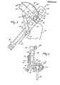
- the box-like frame portion 1 is provided with a trestle 21 which constitutes a three-point hitch for coupling the machine to the three-point lifting device of a tractor.
- the plate 12 positioned near the centre is provided near its upper side with a transverse shaft 22 which, seen in plan view, is positioned just before the roller 16 and which constitutes an attachment point for a bifurcate portion of an adjusting member 23 that is pivotal thereabout.
- the adjusting member 23 is fitted pivotally by means of an attachment point constituted by a detachable pin 24 to a lug 25 located near the upper side of the trestle 21 and fitted to a transverse beam 26 of this trestle.
- the lug 25 is located near the uppermost coupling point of the three-point hitch on the trestle 21.
- the adjusting member 23 comprises two portions 27 and 28 which can be moved telescopically relative to each other.
- the upper portion 28 is capable of sliding in the lower portion 27 and has teeth forming part of a locking mechanism 29 which, arranged on the lower portion, has a locking portion 30.
- Said locking portion 30 can be made inoperative by means of a handle 31 operable from the tractor via a flexible pull member 32, the arrangement being such that, when the lifting device of the tractor is moved downwardly, the upper portion 28 of the adjusting member 23 is pushed into the lower portion 27. After the pull member 32 has been released, the two portions 27 and 28 are automatically fixed relative to each other by means of the locking portion 30.
- the upper portion 28 of the adjusting member 23 has two spaced-apart portions 33 in the form of plates, which are located on both sides of the lug 25.
- the plate- shaped portions 33 have a slot 34, through which the pin 24 is inserted ( Figures 3 and 4).
- Strips 35 having a width corresponding to that of the portions 33 are positioned on both sides of the portions 33 ( Figure 4).
- the strips 35 are retained in position by means of the pin 24 and a bolt 36 located near the centre.
- the bolt 36 which is inserted through the slot 34, is surrounded by a spacer bush 37 disposed between the strips.
- the strips 35 At their upper sides the strips 35 have an aperture, through which a detachable pin 38 is inserted, the arrangement being such that a movement of the portions 33 with respect to the strips 35 and the lug 25 is not possible anymore.
- the bolt 36 ensures the connection of a support 39, which extends at least substantially perpendicularly to the strips 35 and is directed obliquely rearwardly and upwardly.
- the support 39 is constituted by a U-profile and bears via a folded portion against the front side of the, seen in the direction of operative travel A, right-hand strip 35. At its upper side the support 39 is provided with a lug 40A, through which the flexible pull member 32 is passed.
- the front side of the support 39 is provided with a curved strip 40 which, at its front side, has a graduated scale ( Figure 4) ranging from 0 to 30.
- a pointer 41 constituted by the right-angled portion of an arm 42 can move along the graduated scale on the strip 40.
- the arm 42 is fitted pivotally by means of a bolt 43 to a plate 44A which is located near the centre of the support 39 and at the same time supports the centre of the curved strip 40 having the graduated scale.
- An arm 44 which is at right angles to the arm 42, is capable of pivoting together with this arm around the bolt 43.
- the lower end of the arm 44 is in hinging connection with one end of a rod 45, which extends at least substantially parallel to the upper portion 28 of the adjusting member 23 and is in hinging connection with a lug 46 on the locking portion 30 of the locking mechanism 29.
- the rod 45 is provided with screw-thread and setting.nuts 47, with the aid of which the rod length, and hence the correct setting of the pointer 41, can be effected.
- the bolt 43 constitutes a pivot shaft for the pointer 41, which pivot shaft is located to the rear of the adjusting member.
- a straight- toothed pinion 48 is provided on each of the shafts 2, the arrangement being such that the pinions 48 on the shafts 2 of adjacent soil cultivating members 3 are in driving connection with each other.
- the shaft 2 of a soil cultivating member 3 is extended upwardly and by means of this extension reaches into a gear box 49, inside which this shaft is in driving connection, via a conical gear transmission and a speed variator 50 located at the rear of the gear box, with a shaft 51 which extends in the direction of operative travel A and, at the front side, projects from the gear box.
- the shaft 51 is connectable to the power take-off shaft of a tractor via an intermediate shaft 52.
- Figures 7 and 8 show a packer roller 53 which forms part of the machine according to the invention and is provided with scrapers 54, a carrier for the scrapers being formed by a profile in which clamping means 56 arranged at the upper side of the scrapers 54 are slidable and lockable.
- clamping means 57 and bolts 57A the carrier 55 is disposed within recessed portions 58 in supports 59 which are detachably connected by means of clamping means 60 and bolts 61 to the beams 10 and 11.
- each soil cultivating member 3 can be driven from the power take-off shaft via the intermediate shaft 52 and the transmission described in the foregoing, the arrangement being such that adjacent soil cultivating members rotate in opposite directions and cultivate by means of their soil cultivating portions 5 at least contiguous strips of soil.
- the working depth of the soil cultivating members 3 can be set by means of the roller 16, respectively 53, which is located behind the soil cultivating members and is supported by a carrier construction 20 and - as has been described above - in this embodiment is constructed as a packer roller.
- the carrier construction 20 of the roller 16, respectively 53 is fixed in the selected position by means of the adjusting member 23 in that the two portions 27 and 28 of the adjusting member are locked relative to each other.
- the upper pin 38 can be removed from the apertures in the strip 35, as a result of which the portions 33 of the upper portion 28 of the adjusting member 23 are capable of sliding in both directions by means of the slot 34 relative to the pin 24 which is supported by the lug 25 on the trestle 21, and thus the frame portion 1 together with the soil cultivating members 3 has a limited degree of movement during operation, so that, for example, damage on hitting hard objects, such as stones, can be avoided.
- a pivoting movement of the frame portion 1 relative to the carrier construction 20 around the transverse shafts located near the front side of the box-like frame portion 1 is possible through a distance which corresponds to the length of the slot 34.
- the position of the carrier construction 20, and hence that of the roller 16, respectively 53, relative to the box-like frame portion 1 must be altered. This can be effected as follows. With the aid of the flexible operation or pull member 32 the locking realised by means of the locking mechanism 29 can be removed, whereafter the lifting device can be moved downwards, so that the carrier construction 20 of the roller 16, respectively 53, and hence the lower portion 27 of the adjusting member 23, are moved upwards. Then the pointer 41 travels along the graduated scale on the strip 40 in a direction indicated by an arrow in Figure 2. A reading of the graduated scale on the strip 40 will tell the tractor driver whether he has reached the correct position. In this connection, it may be assumed that each line of the graduated scale on the strip 40 corresponds to approximately one centimetre. In the chosen position, a locking of the two portions 27 and 28 of the adjusting member 23 is automatically effected by the locking mechanism 29.
- the pointer 41 and the graduated scale on the strip 40 which together constitute an indicator mechanism, are part of the adjusting member 23.
- the whole assembly can easily be removed by detaching the pins 24 and 38, for use with other machines.
- the indicator mechanism constituted by the pointer 41 and the graduated scale on the curved strip 40 can be removed as an integral unit.
Landscapes
- Life Sciences & Earth Sciences (AREA)
- Engineering & Computer Science (AREA)
- Mechanical Engineering (AREA)
- Soil Sciences (AREA)
- Environmental Sciences (AREA)
- Agricultural Machines (AREA)
- Soil Working Implements (AREA)
Applications Claiming Priority (6)
| Application Number | Priority Date | Filing Date | Title |
|---|---|---|---|
| NL8502944 | 1985-10-29 | ||
| NL8502944 | 1985-10-29 | ||
| NL8503204 | 1985-11-21 | ||
| NL8503204 | 1985-11-21 | ||
| NL8600476A NL8600476A (nl) | 1985-10-29 | 1986-02-26 | Grondbewerkingsmachine. |
| NL8600476 | 1986-02-26 |
Publications (2)
| Publication Number | Publication Date |
|---|---|
| EP0222440A1 true EP0222440A1 (de) | 1987-05-20 |
| EP0222440B1 EP0222440B1 (de) | 1989-10-18 |
Family
ID=27352131
Family Applications (1)
| Application Number | Title | Priority Date | Filing Date |
|---|---|---|---|
| EP19860201860 Expired EP0222440B1 (de) | 1985-10-29 | 1986-10-24 | Bodenbearbeitungsgerät |
Country Status (2)
| Country | Link |
|---|---|
| EP (1) | EP0222440B1 (de) |
| DE (1) | DE3666318D1 (de) |
Citations (3)
| Publication number | Priority date | Publication date | Assignee | Title |
|---|---|---|---|---|
| DE2557753A1 (de) * | 1974-12-30 | 1976-07-08 | Lely Nv C Van Der | Bodenbearbeitungs- und drillmaschine |
| AU524172B2 (en) * | 1978-05-03 | 1982-09-02 | Paul Mizzi | Agricultural implement |
| EP0136734A2 (de) * | 1981-05-29 | 1985-04-10 | C. van der Lely N.V. | Bodenbearbeitungsgeräte |
-
1986
- 1986-10-24 DE DE8686201860T patent/DE3666318D1/de not_active Expired
- 1986-10-24 EP EP19860201860 patent/EP0222440B1/de not_active Expired
Patent Citations (3)
| Publication number | Priority date | Publication date | Assignee | Title |
|---|---|---|---|---|
| DE2557753A1 (de) * | 1974-12-30 | 1976-07-08 | Lely Nv C Van Der | Bodenbearbeitungs- und drillmaschine |
| AU524172B2 (en) * | 1978-05-03 | 1982-09-02 | Paul Mizzi | Agricultural implement |
| EP0136734A2 (de) * | 1981-05-29 | 1985-04-10 | C. van der Lely N.V. | Bodenbearbeitungsgeräte |
Also Published As
| Publication number | Publication date |
|---|---|
| EP0222440B1 (de) | 1989-10-18 |
| DE3666318D1 (en) | 1989-11-23 |
Similar Documents
| Publication | Publication Date | Title |
|---|---|---|
| US3983943A (en) | Soil cultivating implement combinations | |
| US3821989A (en) | Rotary harrows | |
| US4051904A (en) | Soil cultivating implements | |
| EP0271119B1 (de) | Bodenbearbeitungsmaschine | |
| US4114695A (en) | Rotary harrow with pivotable coupling assembly | |
| US3848677A (en) | Soil cultivating implements and screening elements | |
| US4363362A (en) | Multiple machine for row-cropping with vertically operating axes | |
| EP0337533B1 (de) | Mechanisch angetriebenes Bodenbearbeitungsgerät | |
| US3944000A (en) | Rotary harrows | |
| EP0422721A1 (de) | Landwirtschaftliches Gerät, insbesondere Bodenbearbeitungsmaschine | |
| EP0436975A1 (de) | Bodenbearbeitungsmaschine | |
| US4042041A (en) | Rotary harrows | |
| EP0222440A1 (de) | Bodenbearbeitungsgerät | |
| EP0345899A1 (de) | Bodenbearbeitungsmaschine | |
| GB2130862A (en) | Soil cultivating implements | |
| US4099575A (en) | Soil cultivating implements | |
| EP0338646A2 (de) | Kultivator | |
| EP0305601B1 (de) | Gerät zur Bodenbearbeitung | |
| EP0181044B1 (de) | Bodenbearbeitungsgeräte | |
| EP0288125A1 (de) | Bodenbearbeitungsmaschine | |
| EP0666015B1 (de) | Laudwirtschaftliche Maschine | |
| EP0200273A1 (de) | Bodenbearbeitungsmaschine | |
| EP0244038B1 (de) | Bodenbearbeitungsgeräte | |
| EP0264987A1 (de) | Bodenbearbeitungsmaschine | |
| EP0298554A1 (de) | Bodenbearbeitungsmaschine |
Legal Events
| Date | Code | Title | Description |
|---|---|---|---|
| PUAI | Public reference made under article 153(3) epc to a published international application that has entered the european phase |
Free format text: ORIGINAL CODE: 0009012 |
|
| AK | Designated contracting states |
Kind code of ref document: A1 Designated state(s): DE FR GB NL |
|
| 17P | Request for examination filed |
Effective date: 19871030 |
|
| 17Q | First examination report despatched |
Effective date: 19880804 |
|
| GRAA | (expected) grant |
Free format text: ORIGINAL CODE: 0009210 |
|
| STAA | Information on the status of an ep patent application or granted ep patent |
Free format text: STATUS: THE PATENT HAS BEEN GRANTED |
|
| AK | Designated contracting states |
Kind code of ref document: B1 Designated state(s): DE FR GB NL |
|
| REF | Corresponds to: |
Ref document number: 3666318 Country of ref document: DE Date of ref document: 19891123 |
|
| ET | Fr: translation filed | ||
| PLBE | No opposition filed within time limit |
Free format text: ORIGINAL CODE: 0009261 |
|
| PLBI | Opposition filed |
Free format text: ORIGINAL CODE: 0009260 |
|
| PLAA | Information modified related to event that no opposition was filed |
Free format text: ORIGINAL CODE: 0009299DELT |
|
| 26 | Opposition filed |
Opponent name: LIBERTY Effective date: 19900718 |
|
| 26N | No opposition filed | ||
| NLR1 | Nl: opposition has been filed with the epo |
Opponent name: LIBERTY. |
|
| PLBJ | Opposition found inadmissible |
Free format text: ORIGINAL CODE: 0009275 |
|
| 26U | Opposition found inadmissible | ||
| NLXE | Nl: other communications concerning ep-patents (part 3 heading xe) |
Free format text: PAT.BUL.22/90:OPPOSITION 01 HAS BEEN DECLARED INADMISSABLE (SEE EUROPEAN PATENT BULLETIN 210695/25) |
|
| PGFP | Annual fee paid to national office [announced via postgrant information from national office to epo] |
Ref country code: FR Payment date: 20011002 Year of fee payment: 16 |
|
| PGFP | Annual fee paid to national office [announced via postgrant information from national office to epo] |
Ref country code: GB Payment date: 20011004 Year of fee payment: 16 Ref country code: DE Payment date: 20011004 Year of fee payment: 16 |
|
| PGFP | Annual fee paid to national office [announced via postgrant information from national office to epo] |
Ref country code: NL Payment date: 20011009 Year of fee payment: 16 |
|
| REG | Reference to a national code |
Ref country code: GB Ref legal event code: IF02 |
|
| PG25 | Lapsed in a contracting state [announced via postgrant information from national office to epo] |
Ref country code: GB Free format text: LAPSE BECAUSE OF NON-PAYMENT OF DUE FEES Effective date: 20021024 |
|
| PG25 | Lapsed in a contracting state [announced via postgrant information from national office to epo] |
Ref country code: NL Free format text: LAPSE BECAUSE OF NON-PAYMENT OF DUE FEES Effective date: 20030501 Ref country code: DE Free format text: LAPSE BECAUSE OF NON-PAYMENT OF DUE FEES Effective date: 20030501 |
|
| GBPC | Gb: european patent ceased through non-payment of renewal fee |
Effective date: 20021024 |
|
| PG25 | Lapsed in a contracting state [announced via postgrant information from national office to epo] |
Ref country code: FR Free format text: LAPSE BECAUSE OF NON-PAYMENT OF DUE FEES Effective date: 20030630 |
|
| NLV4 | Nl: lapsed or anulled due to non-payment of the annual fee |
Effective date: 20030501 |
|
| REG | Reference to a national code |
Ref country code: FR Ref legal event code: ST |
|
| RIN2 | Information on inventor provided after grant (corrected) |
Inventor name: BOM, CORNELIS JOHANNES GERARDUS Inventor name: VAN DER LELY, ARY |