EP0222450A2 - Procédé et appareil d'estimation de la pente de l'atténuation ultrasonore en fonction de la fréquence dans un milieu de propagation à partir de l'enveloppe complexe d'un signal - Google Patents
Procédé et appareil d'estimation de la pente de l'atténuation ultrasonore en fonction de la fréquence dans un milieu de propagation à partir de l'enveloppe complexe d'un signal Download PDFInfo
- Publication number
- EP0222450A2 EP0222450A2 EP86201940A EP86201940A EP0222450A2 EP 0222450 A2 EP0222450 A2 EP 0222450A2 EP 86201940 A EP86201940 A EP 86201940A EP 86201940 A EP86201940 A EP 86201940A EP 0222450 A2 EP0222450 A2 EP 0222450A2
- Authority
- EP
- European Patent Office
- Prior art keywords
- transfer function
- frequency
- complex
- medium
- signal
- Prior art date
- Legal status (The legal status is an assumption and is not a legal conclusion. Google has not performed a legal analysis and makes no representation as to the accuracy of the status listed.)
- Granted
Links
Images

Classifications
-
- G—PHYSICS
- G01—MEASURING; TESTING
- G01S—RADIO DIRECTION-FINDING; RADIO NAVIGATION; DETERMINING DISTANCE OR VELOCITY BY USE OF RADIO WAVES; LOCATING OR PRESENCE-DETECTING BY USE OF THE REFLECTION OR RERADIATION OF RADIO WAVES; ANALOGOUS ARRANGEMENTS USING OTHER WAVES
- G01S7/00—Details of systems according to groups G01S13/00, G01S15/00, G01S17/00
- G01S7/52—Details of systems according to groups G01S13/00, G01S15/00, G01S17/00 of systems according to group G01S15/00
- G01S7/52017—Details of systems according to groups G01S13/00, G01S15/00, G01S17/00 of systems according to group G01S15/00 particularly adapted to short-range imaging
- G01S7/52053—Display arrangements
- G01S7/52057—Cathode ray tube displays
- G01S7/5206—Two-dimensional coordinated display of distance and direction; B-scan display
-
- G—PHYSICS
- G01—MEASURING; TESTING
- G01S—RADIO DIRECTION-FINDING; RADIO NAVIGATION; DETERMINING DISTANCE OR VELOCITY BY USE OF RADIO WAVES; LOCATING OR PRESENCE-DETECTING BY USE OF THE REFLECTION OR RERADIATION OF RADIO WAVES; ANALOGOUS ARRANGEMENTS USING OTHER WAVES
- G01S7/00—Details of systems according to groups G01S13/00, G01S15/00, G01S17/00
- G01S7/52—Details of systems according to groups G01S13/00, G01S15/00, G01S17/00 of systems according to group G01S15/00
- G01S7/52017—Details of systems according to groups G01S13/00, G01S15/00, G01S17/00 of systems according to group G01S15/00 particularly adapted to short-range imaging
- G01S7/52023—Details of receivers
- G01S7/52036—Details of receivers using analysis of echo signal for target characterisation
Definitions
- the invention relates to a method for measuring the local slope of the ultrasound attenuation versus frequency curve of a propagation medium comprising the steps of:
- the invention also relates to an apparatus for measuring the local slope of the ultrasound attenuation versus frequency curve at points in an object comprising:
- Most echo ultrasound imaging apparatus of the prior art generates images of structures within a body wherein the brightness of individual pixels corresponds to the magnitude of local discontinuities in the acoustic impedance at corresponding points in the body.
- U.S. Patent 4,389,893 is incorporated herein, by reference, as background material. That patent describes apparatus which utilizes differential measurements of echo intensities along A-lines to estimate local tissue attenuation. A raster scan is used to generate images from such A-line measurements.
- U.S. Patent 4,515,163 also describes a method for determining local tissue attenuation from the positions of zero crossings in A-line signals.
- the method and apparatus of the invention operate directly on the complex envelope of a radio frequency pulse-echo signal.
- the complex envelope can be sampled at a much lower rate than the RF signal without suffering from aliasing error.
- the signal processing circuitry of the scanner is thus significantly simplified.
- the average frequency of the complex envelope of an ultrasound pulse which propagates through a medium is zero.
- the presence of frequency-dependent attenuation causes the average frequency of the complex envelope to shift away from zero.
- This variation is measured using an FM detector.
- the output of the detector is used as negative feedback to control the transfer function a compensating filter so that the filter drives the average frequency of the shifted complex envelope back to zero.
- the feedback signal thus sets parameters of the compensating filter. Those parameters are a measure of the attenuation parameters of the propagation medium.
- the tissue characteristics change with depth and the para meters of compensating filter track them.
- the invention thus provides an system that continuously adapts itself to the properties of the medium undergoing measurement.
- a real, stationary random signal, v i (t), propagates through a medium in which the attenuation is a function of frequency.
- the resulting output signal is v o (t).
- the invention infers properties of the medium attenuation from signal processing operations on vi(t) and v o (t).
- E ⁇ ⁇ (t) ⁇ and E ⁇ ⁇ (t) ⁇ are the expected values of the time derivatives of ⁇ (t) and #(t) respectively. From these equations it is clear that the average slope of the signal ⁇ (t) can be made zero by a proper choice of the reference frequency fo.
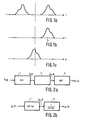
- Figure 1a represents the power spectrum of a real signal v(t)
- Figure 1 represents the power spectrum of the complex analytic representation y(t) of the signal of Figure 1a
- Figure 1 represents the power spectrum of the complex envelope (t) of the signal of Figure 1 a.
- the transfer function of the medium is G(f) A e -kf , f 0, ( 17 )
- the complex impulse response of the filter is:
- FIG. 4 illustrates an implementation of an attenuation scanner. Electrical pulses from an ultrasound pulse transmitter 10 are directed through a TR switch 15 to an ultrasound transducer 20.
- the transducer produces pulses of ultrasound energy which propagate into an object 25 where they produce echoes which are reflected back to the transducer.
- the echoes produce electrical signals in the transducer 20 which are again directed through the TR switch 15 to a receiver 30 where they are amplified in a conventional manner.
- the echo signals may be processed in a conventional AM detector -TGC circuit 35 to produce an image which is presented on a CRT display 40 in a conventional manner.
- the transmitter, detector, and display operate under the influence of a scanning and control circuit 45 which also electrically or mechanically scans the beam of ultrasound energy produced by the transducer over a sector of the object 25.
- the output signal v o (t) of the receiver 30 is also fed to a complex demodulator circuit 50 which, at its output, produces a signal which corresponds to the complex envelope of the received signal.
- Digital implementations of a complex demodulator are described, for example, in United States Patent 4,481,646 and in "Theory and Implementation of the discrete Hilbert Transform", Gold et al in Digital Signal Processing, L. Rabiner, Ed; IEEE Press 1972.
- the output of the complex demodulator 50 is sampled, in a sampling circuit 55 to produce a signal ⁇ o (n).
- the sampling circuit 55 need only operate at a rate equal to twice the highest frequency component in the complex envelope.
- the output of the sampler 55 is fed to the input of a digital compensating filter 60, which is implemented in the manner described in the previous paragraphs.
- the output of the compensating filter, ⁇ i (n) represents the compensated complex envelope of the echo signal. If the digital compensating filter parameters are correctly chosen the compensated complex envelope will correspond to the complex envelope of the transmitted signal v (t) and will have a zero average frequency.
- the compensated complex envelope signal is fed to a digital FM detector 65.
- the output of the digital FM detector, ⁇ ; (n) corresponds directly to the local value of the slope of the frequency dependent attenuation of the propagation medium 25. It may be applied directly to the display 40, for example to modulate the color of the display produced by the conventional AM detector 35.
- the output of the digital FM detector 65 is also fed to the input of an accumulator circuit 70 having a transfer function
- the filter 60, FM detector 65 and accumulator 70 thus function as a negative feedback loop which continually forces the average frequency of the output of the digital compensating filter to zero to maintain the filter characteristic as the inverse of the frequency dependent characteristic of the propagating medium 25.
Landscapes
- Engineering & Computer Science (AREA)
- Computer Networks & Wireless Communication (AREA)
- Physics & Mathematics (AREA)
- General Physics & Mathematics (AREA)
- Radar, Positioning & Navigation (AREA)
- Remote Sensing (AREA)
- Ultra Sonic Daignosis Equipment (AREA)
- Investigating Or Analyzing Materials By The Use Of Ultrasonic Waves (AREA)
Applications Claiming Priority (2)
| Application Number | Priority Date | Filing Date | Title |
|---|---|---|---|
| US795801 | 1985-11-07 | ||
| US06/795,801 US4676250A (en) | 1985-11-07 | 1985-11-07 | Method and apparatus for estimating the attenuation-vs-frequency slope of a propagation medium from the complex envelope of a signal |
Publications (3)
| Publication Number | Publication Date |
|---|---|
| EP0222450A2 true EP0222450A2 (fr) | 1987-05-20 |
| EP0222450A3 EP0222450A3 (en) | 1987-10-14 |
| EP0222450B1 EP0222450B1 (fr) | 1991-10-09 |
Family
ID=25166488
Family Applications (1)
| Application Number | Title | Priority Date | Filing Date |
|---|---|---|---|
| EP86201940A Expired EP0222450B1 (fr) | 1985-11-07 | 1986-11-07 | Procédé et appareil d'estimation de la pente de l'atténuation ultrasonore en fonction de la fréquence dans un milieu de propagation à partir de l'enveloppe complexe d'un signal |
Country Status (6)
| Country | Link |
|---|---|
| US (1) | US4676250A (fr) |
| EP (1) | EP0222450B1 (fr) |
| JP (1) | JPS62116254A (fr) |
| CA (1) | CA1263472A (fr) |
| DE (1) | DE3681880D1 (fr) |
| IL (1) | IL80494A0 (fr) |
Cited By (4)
| Publication number | Priority date | Publication date | Assignee | Title |
|---|---|---|---|---|
| EP0657747A1 (fr) * | 1993-12-07 | 1995-06-14 | Matsushita Electric Industrial Co., Ltd. | Appareil diagnostique à ultrasons |
| EP0713102A1 (fr) * | 1994-11-16 | 1996-05-22 | Advanced Technology Laboratories, Inc. | Systèmes d'imagerie par ultrasons avec autodiagnostique |
| WO2000077945A3 (fr) * | 1999-06-09 | 2001-07-05 | Beamcontrol Aps | Procede determinant le gain d'un canal entre emetteurs et recepteurs |
| CN111358498A (zh) * | 2020-03-23 | 2020-07-03 | 贵州民族大学 | 去除超声脉搏波上冲段反射波和量化噪声的方法及系统 |
Families Citing this family (5)
| Publication number | Priority date | Publication date | Assignee | Title |
|---|---|---|---|---|
| US5253530A (en) * | 1991-08-12 | 1993-10-19 | Letcher Iii John H | Method and apparatus for reflective ultrasonic imaging |
| US20030142875A1 (en) * | 1999-02-04 | 2003-07-31 | Goertzen Kenbe D. | Quality priority |
| US20030185455A1 (en) * | 1999-02-04 | 2003-10-02 | Goertzen Kenbe D. | Digital image processor |
| JP2003521748A (ja) * | 2000-02-02 | 2003-07-15 | クビス・インク | ピクセル化画像形成デバイスを用いて画像解像度を最適化するシステム及び方法 |
| AU5245101A (en) * | 2000-04-25 | 2001-11-07 | Eskom | Low noise to signal evaluation |
Family Cites Families (7)
| Publication number | Priority date | Publication date | Assignee | Title |
|---|---|---|---|---|
| US3805596A (en) * | 1972-02-24 | 1974-04-23 | C Klahr | High resolution ultrasonic imaging scanner |
| US4043181A (en) * | 1975-04-18 | 1977-08-23 | New York Institute Of Technology | Ultrasonic pulse-echo apparatus |
| DE2724437B1 (de) * | 1977-05-31 | 1978-06-15 | Siemens Ag | Nach dem Impuls-Echo-Verfahren arbeitendes Ultraschall-Bildgeraet |
| US4202215A (en) * | 1978-10-26 | 1980-05-13 | Kurt Orban Company, Inc. | Sonic pulse-echo method and apparatus for determining attenuation coefficients |
| DE3174147D1 (en) * | 1981-11-30 | 1986-04-24 | Ibm | Method for receiving a data signal with double side-band quadrature carrier modulation |
| US4543826A (en) * | 1982-06-03 | 1985-10-01 | The Regents Of The University Of California | Ultrasonic acoustic imaging apparatus |
| FR2556845B1 (fr) * | 1983-12-16 | 1986-04-11 | Cgr Ultrasonic | Procede de caracterisation par ondes acoustiques de la structure d'un milieu et dispositif mettant en oeuvre ce procede |
-
1985
- 1985-11-07 US US06/795,801 patent/US4676250A/en not_active Expired - Fee Related
-
1986
- 1986-11-04 IL IL80494A patent/IL80494A0/xx not_active IP Right Cessation
- 1986-11-06 JP JP61262874A patent/JPS62116254A/ja active Pending
- 1986-11-06 CA CA000522388A patent/CA1263472A/fr not_active Expired
- 1986-11-07 DE DE8686201940T patent/DE3681880D1/de not_active Expired - Lifetime
- 1986-11-07 EP EP86201940A patent/EP0222450B1/fr not_active Expired
Cited By (8)
| Publication number | Priority date | Publication date | Assignee | Title |
|---|---|---|---|---|
| EP0657747A1 (fr) * | 1993-12-07 | 1995-06-14 | Matsushita Electric Industrial Co., Ltd. | Appareil diagnostique à ultrasons |
| US5507293A (en) * | 1993-12-07 | 1996-04-16 | Matsushita Electric Industrial Co., Ltd. | Ultrasonic diagnostic apparatus |
| EP0913703A1 (fr) * | 1993-12-07 | 1999-05-06 | Matsushita Electric Industrial Co., Ltd. | Appareil diagnostique à ultrasons |
| EP0713102A1 (fr) * | 1994-11-16 | 1996-05-22 | Advanced Technology Laboratories, Inc. | Systèmes d'imagerie par ultrasons avec autodiagnostique |
| WO2000077945A3 (fr) * | 1999-06-09 | 2001-07-05 | Beamcontrol Aps | Procede determinant le gain d'un canal entre emetteurs et recepteurs |
| US6799141B1 (en) | 1999-06-09 | 2004-09-28 | Beamcontrol Aps | Method for determining the channel gain between emitters and receivers |
| CN111358498A (zh) * | 2020-03-23 | 2020-07-03 | 贵州民族大学 | 去除超声脉搏波上冲段反射波和量化噪声的方法及系统 |
| CN111358498B (zh) * | 2020-03-23 | 2021-08-24 | 贵州民族大学 | 去除超声脉搏波上冲段反射波和量化噪声的方法及系统 |
Also Published As
| Publication number | Publication date |
|---|---|
| US4676250A (en) | 1987-06-30 |
| EP0222450A3 (en) | 1987-10-14 |
| CA1263472A (fr) | 1989-11-28 |
| EP0222450B1 (fr) | 1991-10-09 |
| DE3681880D1 (de) | 1991-11-14 |
| IL80494A0 (en) | 1987-02-27 |
| JPS62116254A (ja) | 1987-05-27 |
Similar Documents
| Publication | Publication Date | Title |
|---|---|---|
| US4584880A (en) | Tissue signature tracking tranceiver | |
| EP0041403B1 (fr) | Procédé et appareil pour la mesure par ondes ultrasonores des caractéristiques de la structure interne d'un objet | |
| US4016750A (en) | Ultrasonic imaging method and apparatus | |
| US3934458A (en) | Method and apparatus for pulse echo imaging | |
| US4852576A (en) | Time gain compensation for ultrasonic medical imaging systems | |
| US5261280A (en) | Tissue signature tracking transceiver | |
| EP0222450B1 (fr) | Procédé et appareil d'estimation de la pente de l'atténuation ultrasonore en fonction de la fréquence dans un milieu de propagation à partir de l'enveloppe complexe d'un signal | |
| US4543826A (en) | Ultrasonic acoustic imaging apparatus | |
| US4446737A (en) | Method and device for measuring objects using ultrasound echography | |
| EP0279314A1 (fr) | Appareil d'examen par ultrasons | |
| EP0248623A2 (fr) | Appareil de balayage à ultrason | |
| US4452085A (en) | Method and means for generating time gain compensation control signal for use in ultrasonic scanner and the like | |
| JPS6111659A (ja) | 超音波検査装置 | |
| EP0107172A2 (fr) | Système ultrasonore de formation d'image utilisant un filtre commandé par l'opérateur pour la compensation de l'atténuation du signal réfléchi | |
| US4534359A (en) | Method and means for determining frequency selective tissue attenuation in a baseband ultrasonic imaging system | |
| US4086818A (en) | Ultrasonic imaging apparatus | |
| EP0202695B1 (fr) | Appareil pour échographie ultrasonore utilisant la détection AM-FM combinée avec domaine dynamique agrandi | |
| JPH0360493B2 (fr) | ||
| JP3022108B2 (ja) | 超音波送受信装置 | |
| JP3243237B2 (ja) | 超音波診断装置 | |
| JPH03143432A (ja) | 分散圧縮方式の超音波診断装置 | |
| JPS6321047A (ja) | 超音波診断装置 | |
| JP2778145B2 (ja) | 超音波診断装置 | |
| Bryant et al. | Adaptive gain control and contrast improvement for medical diagnostic ultrasound B-mode imaging system using charge-coupled devices | |
| JPS624976B2 (fr) |
Legal Events
| Date | Code | Title | Description |
|---|---|---|---|
| PUAI | Public reference made under article 153(3) epc to a published international application that has entered the european phase |
Free format text: ORIGINAL CODE: 0009012 |
|
| AK | Designated contracting states |
Kind code of ref document: A2 Designated state(s): DE FR GB |
|
| PUAL | Search report despatched |
Free format text: ORIGINAL CODE: 0009013 |
|
| AK | Designated contracting states |
Kind code of ref document: A3 Designated state(s): DE FR GB |
|
| 17P | Request for examination filed |
Effective date: 19880402 |
|
| 17Q | First examination report despatched |
Effective date: 19900605 |
|
| GRAA | (expected) grant |
Free format text: ORIGINAL CODE: 0009210 |
|
| AK | Designated contracting states |
Kind code of ref document: B1 Designated state(s): DE FR GB |
|
| REF | Corresponds to: |
Ref document number: 3681880 Country of ref document: DE Date of ref document: 19911114 |
|
| ET | Fr: translation filed | ||
| PLBE | No opposition filed within time limit |
Free format text: ORIGINAL CODE: 0009261 |
|
| STAA | Information on the status of an ep patent application or granted ep patent |
Free format text: STATUS: NO OPPOSITION FILED WITHIN TIME LIMIT |
|
| 26N | No opposition filed | ||
| REG | Reference to a national code |
Ref country code: FR Ref legal event code: CD |
|
| PGFP | Annual fee paid to national office [announced via postgrant information from national office to epo] |
Ref country code: GB Payment date: 19941031 Year of fee payment: 9 |
|
| PGFP | Annual fee paid to national office [announced via postgrant information from national office to epo] |
Ref country code: FR Payment date: 19941125 Year of fee payment: 9 |
|
| PGFP | Annual fee paid to national office [announced via postgrant information from national office to epo] |
Ref country code: DE Payment date: 19950124 Year of fee payment: 9 |
|
| PG25 | Lapsed in a contracting state [announced via postgrant information from national office to epo] |
Ref country code: GB Effective date: 19951107 |
|
| GBPC | Gb: european patent ceased through non-payment of renewal fee |
Effective date: 19951107 |
|
| PG25 | Lapsed in a contracting state [announced via postgrant information from national office to epo] |
Ref country code: FR Effective date: 19960731 |
|
| PG25 | Lapsed in a contracting state [announced via postgrant information from national office to epo] |
Ref country code: DE Effective date: 19960801 |
|
| REG | Reference to a national code |
Ref country code: FR Ref legal event code: ST |