EP0222602A2 - Fusible thermique - Google Patents
Fusible thermique Download PDFInfo
- Publication number
- EP0222602A2 EP0222602A2 EP86308686A EP86308686A EP0222602A2 EP 0222602 A2 EP0222602 A2 EP 0222602A2 EP 86308686 A EP86308686 A EP 86308686A EP 86308686 A EP86308686 A EP 86308686A EP 0222602 A2 EP0222602 A2 EP 0222602A2
- Authority
- EP
- European Patent Office
- Prior art keywords
- lead wire
- fuse
- case
- ball contacts
- alloy
- Prior art date
- Legal status (The legal status is an assumption and is not a legal conclusion. Google has not performed a legal analysis and makes no representation as to the accuracy of the status listed.)
- Withdrawn
Links
Images
Classifications
-
- H—ELECTRICITY
- H01—ELECTRIC ELEMENTS
- H01H—ELECTRIC SWITCHES; RELAYS; SELECTORS; EMERGENCY PROTECTIVE DEVICES
- H01H37/00—Thermally-actuated switches
- H01H37/74—Switches in which only the opening movement or only the closing movement of a contact is effected by heating or cooling
- H01H37/76—Contact member actuated by melting of fusible material, actuated due to burning of combustible material or due to explosion of explosive material
- H01H37/764—Contact member actuated by melting of fusible material, actuated due to burning of combustible material or due to explosion of explosive material in which contacts are held closed by a thermal pellet
- H01H37/765—Contact member actuated by melting of fusible material, actuated due to burning of combustible material or due to explosion of explosive material in which contacts are held closed by a thermal pellet using a sliding contact between a metallic cylindrical housing and a central electrode
Definitions
- This invention relates to a thermal fuse which can be constructed easily and automatically and yet works accurately.
- a thermal fuse is connected to an electric circuit in order to act as a safety means.
- the fuse is so designed that when a preset temperature is reached, a fusible alloy in it fuses and the electric circuit is opened, thereby protecting electric appliances and preventing a fire.
- this thermal fuse two lead wires which in their normal state are separated from each other are brought compulsorily into contact with each other and deposited with fusible alloy to close the circuit between the lead wires. Therefore, when the temperature of the protected electronic circuit itself rises to the preset temperature due to an excess current (at overload) or when the ambient temperature rises excessively, the fusible alloy fuses and thus the circuit is opened.
- this thermal fuse it is required to fuse the fusible alloy and to keep the two lead wires in a compressed state until the fused fusible alloy solidifies. Thus, it takes much trouble for deposition of lead wires.
- a thermal fuse characterised in that it comprises a cylindrical conductive case with a lead wire at the bottom side thereof, another lead wire in the case, a solid fuse alloy piece put in the inner bottom part of the case and ball contacts pressed by springs from both sides between the fuse alloy piece and the other lead wire, wherein an electric circuit is formed between the two lead wires through the medium of the ball contacts and the case, the arrangement being such that, when the fuse allow piece fuses at a preset temperature, the ball contacts under spring pressure are released from pressing on the other lead wire and the electric circuit is thus opened.
- the thermal fuse according to the present invention is manufactured in the following way.
- a fuse alloy piece which fuses at the preset temperature is inserted.
- a compressed spring and an alloy flowing out preventive plate are fitted in.
- An insulating lid is fixed at the open end of the case and a further lead wire is inserted in the case through the lid.
- a spring is put on the end portion of the further lead wire in such a fashion that it engages with a protrusion made at the outer periphery of the further lead wire. By compressing the spring an insulating plate is fitted to the lead wire.
- a plurality of ball contacts an electric conductive wire which connect the case and the further lead wire are electrically interposed between the insulating plate and the alloy flowing out preventive plate.
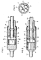
- Figure 1 shows the thermal fuse according to the present invention in its normal condition and Figure 2 shows the same thermal fuse after operation.
- Reference numeral 1 designates a cylindrical case formed of nickel plated copper or iron or formed of electric conductive metal such as aluminium.
- a lead wire L1 is fitted to the outer surface of the bottom of the case 1 by deposition or other means.
- Reference numeral 2 designates a fuse alloy piece to be put in the inner bottom of the case 1. It is made of fusible alloy which fuses at a preset temperature. This fuse alloy piece 2 is put in the inner bottom by using a press or the like.
- Reference numeral 4 designates an alloy flowing out preventive plate to keep fuse alloy piece 2, when fused, from flowing out toward ball contacts 5 and toward the side of the lead wire L2. It is formed of copper or other metal or ceramics and is slidably inserted in the case 1. Between the fuse alloy piece 2 and the alloy flowing out preventive plate 4, a spring 3 is inserted in compressed state. A lid 8 made of ceramic or other insulating material is fixed to an open end portion of the case 1. An opening end edge 11 of the case 1 is bent inwardly to hold a flange 81 of the lid 8 and to fix the lid 8 to the case 1. A hole 82 through which the lead wire L2 is put is made at the centre of lid 8.
- a protrusion L21 is made at the outer periphery of the lead wire L2 and a spring 7 is put on the outer periphery of the lead wire L2 in such a fashion that it engages with the protrusion L21.
- the spring 7 should be weaker in resilience than the spring 3 which presses the alloy flowing out preventive plate 4 and the other end of the spring 7 is supported by one side surface of the insulating plate 6 of washerlike shape fitted to the lead wire L2. The insulating plate 6 is forced to be pushed out toward the fuse alloy piece 2 by the resiliency of the spring 7.
- the insulating plate 6 is made of ceramic, ebonite or other insulating material to withstand the specific temperature and a hole 61 through which the lead wire L2 is put in is made at the centre thereof.
- a plurality of ball contacts 5 are interposed between the insulating plate 6 and the alloy flowing out preventive plate 4.
- the ball contact 5 has a ball-like shape and is made of copper or metal of good conductivity. While the fuse alloy piece 2 is in solid state, both the spring 3 and the spring / are in compressed state and by this spring force, the alloy flowing out preventive plate 4 and the insulating plate 6 are pressed from both directions and a forward end L22 of the lead wire L2 makes contact with the ball contacts 5, which make contact with the inner peripheral surface of the case 1. Thus, between opposing two lead wires L1 and L2, an electric circuit is formed through the medium of ball contacts 5 and the case 1.
- fuse alloy in solid state is put in the case and an electric circuit is formed between two lead wires, through the medium of ball contacts which are under spring pressure from both sides and the case. Therefore, there is no need of fusing fusible alloy for deposition as in the case of the conventional thermal fuse.
- the thermal fuse is easy to construct and the automation is possible for its construction.
Landscapes
- Chemical & Material Sciences (AREA)
- Engineering & Computer Science (AREA)
- Combustion & Propulsion (AREA)
- Fuses (AREA)
Applications Claiming Priority (2)
| Application Number | Priority Date | Filing Date | Title |
|---|---|---|---|
| JP24972685A JPS62110225A (ja) | 1985-11-07 | 1985-11-07 | 温度ヒユ−ズ |
| JP249726/85 | 1985-11-07 |
Publications (2)
| Publication Number | Publication Date |
|---|---|
| EP0222602A2 true EP0222602A2 (fr) | 1987-05-20 |
| EP0222602A3 EP0222602A3 (fr) | 1989-06-14 |
Family
ID=17197284
Family Applications (1)
| Application Number | Title | Priority Date | Filing Date |
|---|---|---|---|
| EP86308686A Withdrawn EP0222602A3 (fr) | 1985-11-07 | 1986-11-07 | Fusible thermique |
Country Status (3)
| Country | Link |
|---|---|
| EP (1) | EP0222602A3 (fr) |
| JP (1) | JPS62110225A (fr) |
| GB (1) | GB2184300A (fr) |
Families Citing this family (2)
| Publication number | Priority date | Publication date | Assignee | Title |
|---|---|---|---|---|
| DE102015224278A1 (de) * | 2015-12-04 | 2017-06-08 | Robert Bosch Gmbh | Elektromagnetisches Relais, insbesondere Starterrelais für eine Startvorrichtung |
| CN111105964B (zh) * | 2018-10-25 | 2022-07-29 | 东洋电子株式会社 | 温敏粒子型温度保险丝 |
Family Cites Families (2)
| Publication number | Priority date | Publication date | Assignee | Title |
|---|---|---|---|---|
| US3781737A (en) * | 1973-02-20 | 1973-12-25 | Essex International Inc | Thermal circuit protector |
| US3992771A (en) * | 1974-05-22 | 1976-11-23 | Emerson Electric Co. | Method of making thermal limiter construction |
-
1985
- 1985-11-07 JP JP24972685A patent/JPS62110225A/ja active Pending
-
1986
- 1986-11-07 EP EP86308686A patent/EP0222602A3/fr not_active Withdrawn
- 1986-11-07 GB GB08626664A patent/GB2184300A/en not_active Withdrawn
Also Published As
| Publication number | Publication date |
|---|---|
| GB8626664D0 (en) | 1986-12-10 |
| EP0222602A3 (fr) | 1989-06-14 |
| JPS62110225A (ja) | 1987-05-21 |
| GB2184300A (en) | 1987-06-17 |
Similar Documents
| Publication | Publication Date | Title |
|---|---|---|
| US5014036A (en) | Thermal and current sensing switch | |
| US6300858B1 (en) | Thermal switch | |
| US4276532A (en) | Thermal fuse | |
| AU656796B2 (en) | Electrical fuse | |
| EP0254382A1 (fr) | Fusible thermique | |
| CA2288106A1 (fr) | Composant electrique pourvu d'un dispositif de sectionnement de securite | |
| US5898355A (en) | Switch breaker having an arc prevention mechanism | |
| US4068204A (en) | Thermal fuse employing a slidable resilient contact member in a conductive housing | |
| EP3511971B1 (fr) | Ensemble de fusible symétrique en plusieurs parties | |
| US4401965A (en) | Thermal switch | |
| KR20160134492A (ko) | 일체형 복합 안전장치 | |
| IE47034B1 (en) | Electrical switch | |
| US4286248A (en) | Thermal cut-off fuse | |
| EP3667692B1 (fr) | Fusible thermique de type pastille thermique | |
| EP0222602A2 (fr) | Fusible thermique | |
| JPS6025855B2 (ja) | 熱応動開閉器 | |
| US4902999A (en) | Enclosed bimetal circuit breaker | |
| CN114868221A (zh) | 限流熔断器 | |
| EP4416751B1 (fr) | Fusible électrique et méthode de fabrication | |
| KR102729095B1 (ko) | 단순한 구조의 온도 퓨즈 | |
| JP3247736U (ja) | 感温ペレット型温度ヒューズ | |
| JPH0536335A (ja) | 熱応動スイツチ及びその製作方法 | |
| JPS606981Y2 (ja) | 温度スイツチ | |
| JPH0438441Y2 (fr) | ||
| JPS5939398Y2 (ja) | 温度ヒュ−ズ |
Legal Events
| Date | Code | Title | Description |
|---|---|---|---|
| PUAI | Public reference made under article 153(3) epc to a published international application that has entered the european phase |
Free format text: ORIGINAL CODE: 0009012 |
|
| AK | Designated contracting states |
Kind code of ref document: A2 Designated state(s): CH DE FR LI NL |
|
| PUAL | Search report despatched |
Free format text: ORIGINAL CODE: 0009013 |
|
| AK | Designated contracting states |
Kind code of ref document: A3 Designated state(s): CH DE FR LI NL |
|
| STAA | Information on the status of an ep patent application or granted ep patent |
Free format text: STATUS: THE APPLICATION IS DEEMED TO BE WITHDRAWN |
|
| 18D | Application deemed to be withdrawn |
Effective date: 19891215 |
|
| RIN1 | Information on inventor provided before grant (corrected) |
Inventor name: OKAZAKI, TASUKU Inventor name: MATSUTANI, YO |