EP0222620B1 - Dispositif pour réduire la force appliquée à un système de guidage par rainure et ergot - Google Patents
Dispositif pour réduire la force appliquée à un système de guidage par rainure et ergot Download PDFInfo
- Publication number
- EP0222620B1 EP0222620B1 EP86308807A EP86308807A EP0222620B1 EP 0222620 B1 EP0222620 B1 EP 0222620B1 EP 86308807 A EP86308807 A EP 86308807A EP 86308807 A EP86308807 A EP 86308807A EP 0222620 B1 EP0222620 B1 EP 0222620B1
- Authority
- EP
- European Patent Office
- Prior art keywords
- lug
- load
- telescoping
- slot
- members
- Prior art date
- Legal status (The legal status is an assumption and is not a legal conclusion. Google has not performed a legal analysis and makes no representation as to the accuracy of the status listed.)
- Expired - Lifetime
Links
- 238000013459 approach Methods 0.000 claims description 5
- IJGRMHOSHXDMSA-UHFFFAOYSA-N Atomic nitrogen Chemical compound N#N IJGRMHOSHXDMSA-UHFFFAOYSA-N 0.000 description 34
- 229910052757 nitrogen Inorganic materials 0.000 description 16
- 239000012530 fluid Substances 0.000 description 15
- 238000012360 testing method Methods 0.000 description 9
- 230000009471 action Effects 0.000 description 8
- 238000004891 communication Methods 0.000 description 8
- 230000004044 response Effects 0.000 description 5
- 230000007423 decrease Effects 0.000 description 2
- 230000003247 decreasing effect Effects 0.000 description 2
- 229910001873 dinitrogen Inorganic materials 0.000 description 2
- 239000003129 oil well Substances 0.000 description 2
- 239000002253 acid Substances 0.000 description 1
- 230000002411 adverse Effects 0.000 description 1
- 230000015572 biosynthetic process Effects 0.000 description 1
- 238000010276 construction Methods 0.000 description 1
- 239000000356 contaminant Substances 0.000 description 1
- 238000005553 drilling Methods 0.000 description 1
- 230000006872 improvement Effects 0.000 description 1
- 238000005461 lubrication Methods 0.000 description 1
- 230000007246 mechanism Effects 0.000 description 1
- 238000003825 pressing Methods 0.000 description 1
- 230000000717 retained effect Effects 0.000 description 1
- 238000007789 sealing Methods 0.000 description 1
Images


Classifications
-
- E—FIXED CONSTRUCTIONS
- E21—EARTH OR ROCK DRILLING; MINING
- E21B—EARTH OR ROCK DRILLING; OBTAINING OIL, GAS, WATER, SOLUBLE OR MELTABLE MATERIALS OR A SLURRY OF MINERALS FROM WELLS
- E21B23/00—Apparatus for displacing, setting, locking, releasing or removing tools, packers or the like in boreholes or wells
- E21B23/004—Indexing systems for guiding relative movement between telescoping parts of downhole tools
- E21B23/006—"J-slot" systems, i.e. lug and slot indexing mechanisms
-
- E—FIXED CONSTRUCTIONS
- E21—EARTH OR ROCK DRILLING; MINING
- E21B—EARTH OR ROCK DRILLING; OBTAINING OIL, GAS, WATER, SOLUBLE OR MELTABLE MATERIALS OR A SLURRY OF MINERALS FROM WELLS
- E21B34/00—Valve arrangements for boreholes or wells
- E21B34/06—Valve arrangements for boreholes or wells in wells
- E21B34/10—Valve arrangements for boreholes or wells in wells operated by control fluid supplied from outside the borehole
- E21B34/108—Valve arrangements for boreholes or wells in wells operated by control fluid supplied from outside the borehole with time delay systems, e.g. hydraulic impedance mechanisms
-
- E—FIXED CONSTRUCTIONS
- E21—EARTH OR ROCK DRILLING; MINING
- E21B—EARTH OR ROCK DRILLING; OBTAINING OIL, GAS, WATER, SOLUBLE OR MELTABLE MATERIALS OR A SLURRY OF MINERALS FROM WELLS
- E21B49/00—Testing the nature of borehole walls; Formation testing; Methods or apparatus for obtaining samples of soil or well fluids, specially adapted to earth drilling or wells
- E21B49/001—Testing the nature of borehole walls; Formation testing; Methods or apparatus for obtaining samples of soil or well fluids, specially adapted to earth drilling or wells specially adapted for underwater installations
Definitions
- the present invention relates generally to apparatus for guiding relative movement between first and second members, and more particularly, but not by way of limitation, to downhole tools including telescoping inner and outer tubular members, relative movement between which is defined by a slot and lug means.
- slot and lug means In many downhole tools for use in performing various testing and treating operations and the like on oil wells, it is desirable to interconnect telescoping inner and outer tubular members by a slot and lug means so that upon exertion of external forces upon one of the inner and outer tubular members, the motion of the one member relative to the other is defined by the permissible movement of the lug within the slot.
- Such slot configurations are generally referred to as J-slots because they very often have the shape of the letter "J", even though many of the slots are very complex in their configurations.
- Ball operated J-slots such as those disclosed in Beck transmit large forces through the ball between the inner and outer tubular members when the ball abuts against - an axial end of the slot.
- U.S. Patent No. 3,823,773 to Nutter discloses a slot, shown in Figure 3, having a lug 105, also shown in Figure 3 and in Figure 2B, received therein.
- the lug and its associated structure are subject to large forces which may be transmitted between the tubular members that are positioned by the lug and slot device of Nutter. As in Beck, such large forces adversely affect the lug and its associated structure.
- a guide lug and slot assembly for guiding inner and outer telescoping tubular members of a downhole tool into a preselected axial position relative to one another, characterised in that it further comprises: a first load lug comprising a substantially annular shoulder fixedly mounted on the radially inner surface of said outer tubular member; and a second load lug fixedly mounted on the radially outer surface of said inner tubular member, said load lugs abuttingly engaging one another when said inner and outer tubular members are guided by said lug and slot assembly to said preselected axial position, said annular shoulder including a slot therein of a size sufficient to permit passage of said second load lug therethrough when said slot and said second load lug are radially aligned with one another.
- the invention also includes a downhole tool comprising : first and second telescoping tubular members; motion control means operatively associated with said first and second telescoping members for controlling relative axial movement between said first and second telescoping tubular members, said motion control means including a groove disposed in one of said first and second tubular members and a guide lug associated with the other of said first and second telescoping tubular members, said guide lug being received in said groove, characterised in that it further comprises first and second abutment surfaces associated with said first and second telescoping tubular members, respectively, said first abutment surface including a slot formed therein through which said second abutment surface may pass when said second abutment surface is radially aligned therewith; wherein said first and second tubular members, said motion control means, and said first and second abutment surfaces are so arranged and constructed that when said guide lug is at an axially extreme position within a leg of said groove, said first abutment surface supportingly engages said second
- the invention further comprises a downhole tool comprising: first and second telescoping members; a guide lug fixedly mounted on one of said first and second telescoping members; a groove disposed in the other of said first and second telescoping members and having said guide lug received therein, said groove having a substantially axial leg which defines a preselected relative axial position of said first and second telescoping members when said guide lug approaches the end of said leg, characterised in that it further comprises first and second load lugs fixedly mounted on said first and second telescoping members, respectively, said first and second load lugs being positioned relative to said guide lug and to said groove so as to abuttingly engage one another when said first and second telescoping members are in said preselected relative axial position, said first load lug comprising an annular shoulder having a slot formed therethrough, said slot being of a size sufficient for said second load lug to pass therethrough when said slot and said second load lug are radially aligned.
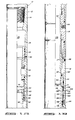
- Figures 1A-1F comprise a quarter section elevational view of one embodiment of downhole tool incorporating an assembly of the present invention.
- Figure 2 is a section elevation right side only view similar to the view of Figure 1B with the tool in a different configuration.
- Figure 3 is a section elevation right side only view similar to the view of 1B with the tool in another configuration.
- Figure 4 is a section elevation right side only view similar to Figure 1B with the tool in yet another configuration.
- Figure 5 is a cross-sectional view of the tool shown in Figures 1A-1F in still another configuration.
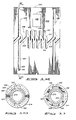
- Figure 6 is an elevational view of a cylindrical sleeve including a groove in the outer surface thereof.
- Figure 7 is a cross-sectional view taken along lines 7-7 in Figure 6.
- Figure 8 is a laid-out view of the sleeve of Figure 6 showing the appearance of the sleeve as if it had been cut along its length at one side and then rolled out flat into a rectangular shape.
- Lines 1B-1B, 2-2, 3-3, and 4-4 indicate the location of the section through which the sleeve is seen in Figures 1B, 2, 3, and 4, respectively.
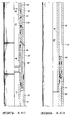
- Figures 9A-F comprise an elevational quarter section view showing a downhole tool incorporating a second embodiment of the assembly of the present invention.
- Figure 10 is a cross-sectional view taken along lines 10-10 in Figure 9E.
- Figure 11 is a cross-sectional view taken along 11-11 in Figure 9E.
- Figure 12 is a laid-out view of a portion of the indexing sleeve of Figure 9E showing the appearance of the sleeve as if it had been cut along its length at one side and then rolled out flat into a rectangular shape.
- the line 9E-9E indicates the location of the section through the sleeve which is seen in Figure 9E.
- a downhole tool constructed in accordance with the instant invention is indicated generally at 10.
- Downhole tool 10 is a recloseable circulation valve for use in oil well testing, which is a slightly modified version of the circulation valve disclosed and claimed in U.S. Patent No. 4,355,685 to Beck and assigned to the assignee of the present invention.
- the particular manner of operation of downhole tool 10 of the present invention is substantially the same as that described in the Beck patent, to which reference should be made for further details.
- Those portions of downhole tool 10 of the present invention, other than the components specifically related to the force reducing assembly, will be described herein only in a brief fashion sufficient that the improvement provided by the force reducing assembly may be appreciated.
- Downhole tool 10 includes a cylindrical housing 12 which is made up of an upper housing adapter 14, an upper intermediate housing section 16 (such including an abutment surface 17 on the lower end thereof), an indexing housing section 18, a passageway housing section 20, a nitrogen chamber housing 22, a lower intermediate housing section 24, an oil chamber housing 26 and a lower housing adapter 28.
- Cylindrical housing 12 includes a longitudinal passageway 29 disposed therethrough, said passageway 29 being comprised of the various internal surfaces of the components of cylindrical housing 12 just described.
- Upper housing adapter 14 includes a circulation port 30 disposed through a side wall thereof.
- a circulation valve cover sleeve 32 is closely received within an inner bore 34 of upper housing adapter 14 and is moveable between a first closed position, as shown in Figure 1A closing circulation port 30.
- circulation valve cover sleeve 32 When circulation valve cover sleeve 32 is in its open position it is displaced upwardly relative to upper adapter 14 from the position shown in Figure 1A.
- Circulation valve cover sleeve 32 is connected to a circulation valve opening mandrel 36 which has a port 38 disposed therein for communication with the circulation port 30 when the circulation valve cover sleeve 32 is moved upwardly to its open position.
- a lower circulation valve sleeve 40 Connected to the lower end of circulation valve opening mandrel 36 is a lower circulation valve sleeve 40.
- a circulation valve operating mandrel 42 is closely received within an inner cylindrical surface 44 of upper intermediate housing section 16.
- An operating collar 46 is threadedly attached to the upper end of circulation valve operating mandrel 42 at threaded connection 48.
- Operating collar 46 has a greater outer diameter than does operating mandrel 42 and includes upward and downward facing surfaces 50, 52, respectively.
- Piston mandrel 58 includes an annular power piston 61 formed on the upper end thereof which is closely received within an inner cylindrical surface 62 of indexing section housing 18.
- Power piston 61 includes an upward-facing or abutment surface 63.
- a lug and slot type indexing section or guide means generally designed by the numeral 64 is connected between piston mandrel 58 and indexing housing section 18 of housing 12 to define the permissible relative movement between piston mandrel 58 and the components attached thereto relative to the cylindrical housing 12.
- the indexing section includes an indexing sleeve 65 which is closely received over mandrel 58. Indexing section 64 is described in more detail below after completion of the general description of downhole tool 10.
- a lower end 66 of piston mandrel 58 is closely received within an inner cylindrical surface 68 of passageway housing section 20.
- An annular space 70 is defined between sleeve 65 and cylindrical housing 12 and is communicated with a lower end or abutment surface 71 of power piston 61.
- an upper inner tubular sleeve 72 Connected to an internally threaded lower end of passageway housing section 20 is an upper inner tubular sleeve 72. Attached to the lower end of sleeve 72, as seen in Figure 1D is a lower inner tubular sleeve 74. A lower end of lower inner tubular sleeve 74 is received within intermediate housing section 24 as shown in Figure 1E. A flow restriction apparatus or metering cartridge 76, to be described more fully hereinafter, is received beneath the lower end of housing 24 and is connected via threads 77 to the upper end of a tubular member 79.
- annular nitrogen chamber 78 Defined between upper inner tubular sleeve 72 and nitrogen chamber housing 22 of housing 12 is an annular nitrogen chamber 78.
- annular oil chamber 80 Defined between lower tubular sleeve 79 and oil chamber housing 26 of housing 12 is an annular oil chamber 80.
- a first floating piston 82 Disposed in nitrogen chamber 78 is a first floating piston 82 which separates nitrogen in nitrogen chamber 78 from oil in oil chamber 80, and which transfers pressure therebetween.
- a second floating piston 84 which separates oil in oil chamber 80 from annulus fluid communicated with the lower side of second floating piston 84 through a port 86 through the side of oil chamber housing 26.
- Nitrogen chamber 78 is communicated with annular space 70 through a passageway 88 disposed longitudinally through the wall of passageway housing section 20.
- first floating piston 82 is communicated with oil chamber 80 through an annular space 90 defined between lower inner tubular sleeve 74 and nitrogen chamber housing 22, and an annular clearance 94 between housing section 24 and lower inner tubular sleeve 74, and through metering cartridge 76.
- Annulus fluid is communicated with the upper end of power piston 61 through a power port 98 through the side wall of indexing housing section 18.
- Metering cartridge 76 permits flow of oil between chamber 80 and annular clearance 94, but only at a relatively slow rate, even in response to a large increase or decrease in pressure chamber 80.
- the metering cartridge serves as a time delay in communicating pressure increases and decreases from oil chamber 80 to nitrogen chamber 78.
- indexing sleeve 65 is disposed about piston mandrel 58 and retained in place thereon by means of a retaining collar 106 and thrust washers as shown which permit sleeve 65 to rotate relative to piston mandrel 58.
- indexing sleeve 65 has disposed in its outer cylindrical surface 110 a continuous groove or slot 112.
- Groove 112 includes an upper repeating zig-zag portion 116 for rotating sleeve 65 counter-clockwise as viewed from above upon reciprocation of piston mandrel 58 relative to housing 12.
- Groove 112 includes a lower repeating zig-zag portion 118 for rotating sleeve 65 in a clockwise direction as viewed from above upon reciprocation of piston mandrel 58 relative to housing 12.
- Slot 112 further includes first and second vertical groove portions 120, 122 for joining upper portion 116 to lower portion 118 as shown.
- Groove 116 includes therein a plurality of upper portions, like upper portions 124, 126, 128. As can best be seen in Figure 7, groove 116 has a semi-circular cross section. Each of the upper portions includes an upper surface, like upper surface 130 in upper portion 128.
- Groove 116 includes a plurality of lower portions, like lower portions 132, 134, 136, and each of the lower portions includes a lower surface, like lower surface 138 in lower portion 136.
- groove 118 includes a plurality of upper portions, like portion 140 and a plurality of lower portions like portion 142, with upper portion 140 having an upper surface 144 and a lower portion 142 having a lower surface 146.
- indexing section 64 includes therein a ball 148, such being held by indexing housing section 18 and being biased into groove 112.
- a force reducing assembly constructed in accordance with the instant invention. Included therein is an annular shoulder 152 formed on the radially inner surface of indexing housing section 18. The shoulder includes a slot 154, also viewable in Figure 5, formed therein. Shoulder 152 includes an upper abutment surface 156 and a lower abutment surface 158. The shoulder is shown in cross section in Figure 5.
- Indexing sleeve 65 includes mounted thereon load lugs 160, 162.
- Each of the load lugs includes an upper abutment surface like upper abutment surface 164 on load lug 160 and a lower abutment surface like abutment surface 166 on load lug 160.
- downhole tool 10 provides a circulation valve which may be moved between its open and closed positions by repeatedly increasing and decreasing the pressure in the annulus between the drill string and the well bore hole.
- Annulus pressure is communicated with the upper end of power piston 61 through power port 98.
- Exerted on lower surface 71 of power piston 61 is the pressure of nitrogen gas contained in nitrogen chamber 78.
- the oil in oil chamber 80 is maintained at a pressure equal to the annulus pressure by means of second floating piston 84, the lower end of which is communicated with annulus fluid through port 86.
- power piston 61 Upon repeated increasing and decreasing of the annulus pressure, power piston 61 is caused to reciprocate relative to housing 12 of downhole tool 10. This reciprocation causes ball 148 to move through groove 112.
- indexing sleeve 65 moves until ball 148 is received within lower portion 132 of groove 116 as shown in dashed lines in Figure 8. Again the ball does not serve as a stop to prevent further upward movement of sleeve 65 but rather surface 164 on lug 160 abuts against surface 158 of shoulder 152 thus halting further upward movement power mandrel 58 as seen in Figure 1B.
- the tool is lowered into the well bore in the position shown in Figure 2.
- FIG. 5 is a cross-sectional view taken while ball 148 is received in portion 120 of groove 112.
- lug 160 is received within and passing through slot 154 of shoulder 152.
- lugs 160, 162 move above shoulder 152.
- FIG. 9A-9F a second embodiment of the instant invention is incorporated in a tool indicated generally at 201.
- Tool 201 includes a cylindrical outer housing, generally designated by the numeral 200, having an upper housing adapter 202 which includes threads 204 for attaching tool 201 to the portion of a testing drill string located above tool 201.
- a lower housing adapter 206 which includes an externally threaded portion 208 for connection of tool 201 to a portion of the test string located below the tool.
- Housing 200 further includes an upper housing section 210, an intermediate housing section 212 and a lower housing section 214.
- the interior of the components making up housing 200 forms a fluid flow passageway 216 axially through tool 201.
- the various housing sections and the upper and lower adapter are threadably connected to one another via threaded connections as shown in the drawing with each such threaded connection being sealed with O-rings as shown.
- a circulation valve Indicated generally at 217 in Figures 9B and 9C is a circulation valve.
- a generally tubular valve mandrel 218 is closely received within upper housing section 210 and is sealingly engaged therewith via O-rings 220, 222, 224, and 226.
- An upper valve sleeve 228 is closely received within upper housing section 210 and is threadably engaged via threads 230 to the upper end of valve mandrel 218.
- An O-ring 231 sealingly engages the radially outer surface of upper valve sleeve 228 to the radially inner surface of upper housing section 210.
- a lower valve sleeve 234, in Figure 9C, is threadably engaged via threads 236 to the lower end of valve mandrel 218 and is sealingly engaged thereto via O-ring seal 238.
- Valve mandrel 218 includes a lower check valve indicated generally at 240. Included therein is a resilient valve portion 242, such comprising an annular lip having a radially outer surface 244 which bears against the radially inner surface of valve mandrel 218. Valve portion 242 is inserted over and carried by a valve portion carrier 246. Carrier 246 supports valve portion 242 to create an annular space 248 between the radially outer surface of the valve portion and the radially inner surface of valve mandrel 218. A plurality of bores, one of which is bore 250, are formed through mandrel 210 about the circumference thereof and permit fluid communication between the exterior of the mandrel and space 248. Upper housing section 210 includes a circulating port 252 to permit fluid communication between the interior and exterior of upper housing section 210.
- Valve carrier 246 is received between the upper end of lower valve sleeve 234 and a bevel 254 formed on the radially inner surface of valve mandrel 218 and is thus restrained from axial movement relative to the valve mandrel.
- an upper check valve is indicated generally at 256. Included therein is a resilient valve portion 258 having an annular lip which has a radially inner surface 260 that is sealingly engaged against the radially outer surface of valve mandrel 218 about its circumference. Resilient valve portion 258 is carried by a valve portion carrier 262. A space 264 is formed between the radially inner surface of resilient valve portion 258 and the radially outer surface of the valve mandrel.
- a plurality of bores indicated generally at 266 provide fluid communication between the interior of the valve mandrel 218 and space 264 about the circumference of the valve mandrel.
- Valve carrier 262 is received between the lower end of upper valve sleeve 228 and a bevel 268 formed on the radially outer surface of valve mandrel 218 about its circumference and is thus restrained from axial movement relative to the valve mandrel.
- a piston mandrel 270 in Figure 9C, 9D, and 9E has an upper end threadably secured via threads 272 to the lower end of lower valve sleeve 234.
- the radially outer surface of piston mandrel 270 and the radially inner surfaces of upper housing section 210 and intermediate housing section 212 define an upper annular space 274 which is in communication with the exterior of the tool via a power port 276.
- O-rings 278, 280 seal the radially inner and outer surfaces of intermediate housing section 212 and define the lower end of annular space 274.
- O-rings 278, 280 define the upper end of a lower annular space 282 which has as its outer boundry the radially inner surface of lower housing section 214.
- the radially inner boundry of space 282 is defined by the outer surface of piston mandrel 270 and the outer surface of a lower piston mandrel 286 which is threadably secured to the lower end of piston mandrel 270 via threads 288.
- annular floating piston 290 Disposed at the lower end of annular space 282 is an annular floating piston 290. Piston 290 is sealingly and slidingly received between the radially outer surface of the lower piston mandrel 286 and the radially inner surface of lower housing section 214. Lower annular space 282 is filled with oil to provide lubrication to moving parts, to be hereinafter more fully described, contained within space 282.
- the lower side of floating piston 290 is in fluid communication with the exterior of tool 201 via a port 293 formed through the wall of lower housing section 214. The floating piston prevents drilling mud and other contaminants in the well bore from becoming mixed with the oil contained in annular space 282 above the floating piston.
- an indexing sleeve 292 is closely received over piston mandrel 270 and is restrained from axial movement therealong by a downward facing shoulder 294 formed on mandrel 270 and the upper surface of lower piston mandrel 286.
- An outer cylindrical surface 296 on indexing sleeve 292 concludes a continuous slot or groove, such being indicated generally at 298.
- Groove 298 includes a repeating zig-zag portion 300 which rotates sleeve 292 counter-clockwise, as viewed from above, upon reciprocation of piston mandrel 270 relative to housing 200.
- Groove 298 further includes first and second vertical groove portions 302, 304.
- Each of groove portions 302, 304 includes an upper and lower leg, like upper leg 305 and lower leg 307 in groove 302.
- Connecting groove portion 306, 308 connect repeating zig-zag portion 300 with vertical groove portions 302, 304.
- Zig-zag portion 300 includes a first leg 310 having an upper surface 312 and a lower surface 314.
- Each of the other legs in zig-zag portion 300 include similar upper and lower surfaces.
- each of vertical grooves 302, 304 include upper and lower surfaces like upper surface 316 and lower surface 318 in groove 302.
- a ball 320 is biased into groove portion 302 and more particularly into the lower portion of the groove as viewed in both Figures 12 and 9E.
- ball 320 is mounted on the radially inner surface of an annular shoulder 324 which is formed on the radially inner surface of lower housing section 214.
- annular shoulder 324 is formed on the radially inner surface of lower housing section 214.
- An annular shoulder 322 is formed on the radially inner surface of lower housing section 214 about its circumference.
- Annular shoulder 322 includes a pair of opposed slots 326, 328 which are viewable in Figure 11.
- Annular shoulder 324 includes a similar pair of opposed slots 330, 332 with slot 330 being axially aligned with slot 336 and slot 332 being axially aligned with slot 328.
- Indexing sleeve 292 includes a pair of opposed load lugs 334, 336, such being viewable in Figure 11.
- opposing lugs 334, 336 are received within slots 326, 328, respectively.
- Load lug 336 is viewable in Figure 12 and is shown in dot-dash lines in Figure 9E, such indicating where load lug 336 is positioned on the rear side of index sleeve 292, with lug 334 being half cut away in the quarter section and half obscured by lower housing section 214.
- Load lug 336 includes an upper abutment surface 338 and a lower abutment surface 340.
- Abutment surfaces 338, 340 comprise the upper and lower surfaces, respectively, of the load lug which extends outwardly from the radially outer surface of indexing sleeve 292.
- annular shoulder 322 includes upper and lower abutment surfaces 342, 344, respectively.
- shoulder 324 includes upper and lower abutment surfaces 346, 348, respectively.
- the upper surface of lower piston mandrel 286 comprise an abutment surface 350 with surface 348 being abutted against surface 350 in the view of Figure 9E.
- Additional abutment surfaces are seen in Figures 9C and 9D and include surface 352 on the lower end of lower valve sleeve 234 and surface 354 on the upper end of intermediate housing section 212. As will be explained hereinafter, the various abutment surfaces interact with one another to limit the axial movement of valve mandrel 218 and thereby place the valve in a closed condition, in a condition for circulation of fluids, or in a condition for reverse circulation of fluids.
- mandrel 270 is axially reciprocated relative to housing 200 in order to place ball 320 in the lower end of leg 310 as shown in dashed lines in Figure 12.
- ball 320 is adjacent lower surface 314.
- abutment surface 338 of load lug 336 and the upper surface of the opposing load lug are abutted against abutment surface 344 on the underside of annular shoulder 322.
- surfaces 338, 344 are so abutted, ball 320 is not abutted against surface 314 on the lower portion of leg 310 but rather is positioned just adjacent thereto.
- valve mandrel 218 When power piston 270 is positioned with ball 320 in leg 310 as described above, valve mandrel 218 is positioned over circulation port 252, in Figure 9C, between O-rings 222, 224. Thus, fluid communication between passageway 216 and the exterior of tool 201 is prevented.
- the tool With the tool configured as described above, it is assembled into the drill string and lowered into the well bore. With this arrangement, fluids may be pumped into the drill string on which tool 201 is suspended for purposes of fracturing or injecting acid into the formation. Also, the annulus between tool 201 and the well bore may be pressurized in order to operate different tools in the drill string testing arrangement.
- passageway 216 is pressurized thus forcing power mandrel 270 downwardly until ball 320 is received in the upper portion of leg 310, as shown in dashed lines in Figure 12, adjacent surface 312.
- the power mandrel is urged downwardly under such pressurization due to the action of an annular piston which is defined by an outer diameter at seal 238 in Figure 9C and by an inner diameter at O-ring 278 in Figure 9E.
- Fluid pressure in passageway 216 acts across the difference in area between seal 238 and O-ring 278 to urge power mandrel 270 downwardly.
- ball 320 moves from the lower portion of leg 310 to the upper portion of leg 310 adjacent upper surface 312.
- circulation port 252 is always between O-rings 222, 224, thus sealing the port from fluid communication between the interior and exterior of the tool.
- ball 320 will be successively moved along zig-zag portion 300 until it is received in the upper portion of the leg to the immediate right of connecting port 306.
- annulus pressure may be applied to urge piston mandrel 370 upwardly thereby causing ball 320 to enter connecting portion 306 and thereafter lower leg 307 as the piston mandrel continues its upward movement.
- Abutment surface 338 does not strike abutment surface 344 on the lower surface of shoulder 233 as during piston mandrel reciprocation when ball 320 is received in zig-zag portion 300. This is because load lugs 334, 336 are received within slots 326, 328, in Figure 11 and thus permit movement of ball 320 down lower leg 307.
- abutment surface 348 on the lower side of shoulder 324 abuts against surface 350 on the upper side of lower piston mandrel 286 thus stopping further mandrel movement and preventing ball 320 from absorbing a significant axial load.
- valve mandrel 218 When ball 320 is in the lower end of leg 307 as shown in the solid-line view of Figure 12 and Figure 9E, valve mandrel 218 is positioned relative to port 252 as shown in Figure 9C. When so positioned fluid may be reverse circulated through port 252, bore 250 (and the other bores about the perimeter of valve mandrel 218 adjacent bore 250), into annular space 248 on the radially inner surface of valve mandrel 218 and into passageway 216.
- valve mandrel 218 when valve mandrel 218 is in the configuration of 9C, the well may be reverse circulated but, because of the action of resilient valve portion 242, the well nay not be circulated from the drill string into the annulus.
- surface 242 sealingly engages the radially inner surface of the valve mandrel thus preventing flow between passageway 216 and the annulus.
- passageway 216 may be pressurized (by pressurizing the drill string) thus driving piston mandrel 270 downwardly and moving ball 320 upwardly in leg 307 and into leg 305 until the ball is adjacent surface 316.
- surface 352 on the lower end of lower valve sleeve 234 abuts against surface 354 on the upper end of intermediate housing section 212 thus stopping further downward movement of piston mandrel and preventing ball 320 from bearing significant forces as a result of impact with surface 316.
- O-ring 220 on valve mandrel 218 is beneath circulating port 252 thus permitting circulation from passageway 216 into the well bore.
- the downhole tool of the present invention readily achieves the ends and advantages mentioned as well as those inherent therein. While presently preferred embodiments of the invention have been specifically described for the purposes of this disclosure, numerous changes in the arrangement and construction of parts can be made by those skilled in the art which changes are encompassed within the spirit and scope of this invention which is defined by the appended claims.
- the invention is not limited to do a specific number of load lugs and slots; more lugs may be provided to further distribute forces and thus reduce those on an individual lug; the lugs may be incorporated into the tool housing and slotted annular shoulder provided on the indexing sleeve.
Landscapes
- Life Sciences & Earth Sciences (AREA)
- Engineering & Computer Science (AREA)
- Geology (AREA)
- Mining & Mineral Resources (AREA)
- Physics & Mathematics (AREA)
- Environmental & Geological Engineering (AREA)
- Fluid Mechanics (AREA)
- General Life Sciences & Earth Sciences (AREA)
- Geochemistry & Mineralogy (AREA)
- Earth Drilling (AREA)
- Support Of Aerials (AREA)
Claims (10)
- Ensemble de guidage à ergot et fente (64, 292, 320), destiné à guider des éléments tubulaires télescopiques, intérieur (58, 270) et extérieur (18 ; 214) appartenant à un outil de fond de forage (10 ; 201) pour les placer dans une position axiale présélectionnée l'un par rapport à l'autre, caractérisé en ce qu'il comprend en outre : un premier ergot de charge (154 ; 322) comprenant un épaulement sensiblement annulaire monté en position fixe sur la surface radialement intérieure dudit élément tubulaire extérieur ; et un deuxième ergot de charge (160 ; 336) fixé rigidement sur la surface radialement extérieure dudit élément tubulaire intérieur, lesdits ergots de charge étant en prise par butée l'un contre l'autre lorsque lesdits éléments tubulaires intérieur et extérieur sont guidés par ledit ensemble à ergot et fente (64 ; 292, 320) pour prendre ladite position axiale présélectionnée, ledit épaulement annulaire intérieurement comportant une fente (154 ; 330, 332) d'une dimension suffisante pour donner passage audit deuxième ergot de charge à travers cette fente lorsque ladite fente et ledit second ergot de charge sont alignés radialement l'un sur l'autre.
- Ensemble selon la revendication 1, caractérisé en ce qu'il comprend en outre un troisième ergot de charge monté sur l'un des éléments tubulaires pour venir buter contre un des autres ergots de charge lorsque lesdits éléments tubulaires intérieur et extérieur sont guidés par ledit ensemble à ergot et fente pour prendre une deuxième position axiale présélectionnée l'un par rapport à l'autre.
- Ensemble selon la revendication 1, caractérisé en ce que lesdits éléments tubulaires télescopiques intérieur et extérieur comprennent des ergots de charge additionnels montés fixes sur lesdites surfaces radialement extérieure et intérieure respectivement, lesdits ergots de charge additionnels étant en butée l'un contre l'autre lorsque lesdits éléments tubulaires intérieur et extérieur sont guidés par ledit ensemble à ergots et fente pour prendre différentes positions axiales présélectionnées l'un par rapport à l'autre.
- Ensemble selon la revendication 1, 2 ou 3, caractérisé en ce que ledit deuxième ergot de charge comprend une surface de butée inférieure pour buter contre le côté supérieur dudit épaulement annulaire et une surface de butée supérieure pour buter contre le côté inférieur dudit épaulement annulaire.
- Ensemble selon la revendication 1, caractérisé en ce que ledit ensemble de guidage à ergot et fente est du type qui engendre un déplacement relatif en rotation entre lesdits éléments tubulaires télescopiques intérieur et extérieur pendant ce guidage et dans lequel ledit deuxième ergot peut être aligné sur ladite fente pour permettre audit ensemble de guidage à ergot et fente de guider lesdits éléments tubulaires télescopiques intérieur et extérieur jusqu'à une position axiale relative qui est au-delà de ladite position axiale présélectionnée.
- Outil de fond de forage comprenant : des premier (18, 214) et deuxième (58, 170) éléments tubulaires télescopiques ; des moyens (64 ; 292, 320) de commande du mouvement qui sont associés fonctionnellement auxdit premier et deuxième éléments télescopiques pour commander le mouvement axial relatif entre ces premier et deuxième éléments tubulaires télescopiques, lesdits moyens de commande du mouvement comprenant une gorge (112 ; 300) disposée dans un des premier et deuxième éléments tubulaires et un ergot de guidage (148 ; 320) associé à l'autre desdits premier et deuxième éléments tubulaires télescopiques, ledit ergot de guidage étant reçu dans ladite gorge, caractérisé en ce qu'il comprend en outre des premières (156, 158 ; 342, 344) et deuxièmes (164, 166 ; 338, 340) surfaces de butée associées aux premier et deuxième éléments tubulaires télescopiques, respectivement, ladite première surface de butée présentant une fente (154 ; 330, 332) qui y est formée et à travers laquelle ladite deuxième surface de butée peut passer lorsque ladite deuxième surface de butée est alignée radialement avec elle ; dans lequel lesdits premier et deuxième éléments tubulaires, lesdits moyens de commande du mouvement et lesdites première et deuxièmes surfaces de butée sont agencés et construits de telle manière que, lorsque ledit ergot de guidage se trouve dans la position axialement extrême à l'intérieur d'une branche de ladite gorge, ladite première surface de butée est en contact avec ladite deuxième surface de butée, en la supportant, pour empêcher ledit ergot de guidage d'exercer des forces axiales notables sur ladite gorge.
- Outil selon la revendication 6, caractérisé en ce que ladite gorge comprend des surfaces supérieure et inférieure dont ledit ergot de guidage peut s'approcher, et qui définissent ainsi des positions axiales relatives desdits premier et deuxième éléments tubulaires télescopiques et dans lequel ledit outil de fond de forage comprend en outre des surfaces de butée additionnelles associées auxdits premier et deuxième éléments tubulaires télescopiques, lesdites surfaces de butée additionnelles étant agencées pour entrer en contact entre elles lorsque lesdits premier et deuxième éléments télescopiques s'approchent de ces positions axiales relatives présélectionnées pour empêcher ledit ergot de guidage d'exercer des forces axiales notables contre lesdites surfaces supérieure et inférieure de la gorge.
- Outil selon la revendication 1, caractérisé en ce que ladite première surface de butée comprend un côté d'un épaulement annulaire et dans lequel ledit ergot de guidage est monté sur ledit épaulement, et dans lequel ladite deuxième surface de butée comprend de préférence un bord d'un ergot de charge et dans lequel ledit épaulement annulaire comprend ladite fente à travers laquelle ledit ergot de charge peut passer lorsque ledit ergot de charge est aligné radialement sur cette fente, ledit deuxième élément télescopique étant de préférence reçu à coulissement dans ledit premier élément télescopique, ladite deuxième surface de butée comprenant de préférence un bord de l'ergot de charge qui s'étend vers l'extérieur à partir de la surface radialement extérieure dudit deuxième élément télescopique, et dans lequel ledit épaulement annulaire comprend de préférence intérieurement ladite fente à travers laquelle ledit ergot de charge peut passer lorsque cet ergot de charge est aligné radialement avec elle.
- Outil de fond de forage comprenant : des premier (18, 214) et deuxième (58, 270) éléments télescopiques : un ergot de guidage (148, 320) monté rigidement sur l'un desdits premier et deuxième éléments télescopiques, une gorge (112, 300) disposée dans l'autre desdits premier et deuxième éléments télescopiques, dans laquelle se loge ledit ergot de guidage, ladite gorge ayant une branche sensiblement axiale (120, 122 : 302, 304) qui définit une position axiale relative présélectionnée desdits premier et deuxième éléments télescopiques lorsque ledit ergot de guidage s'approche de l'extrémité de ladite branche, caractérisé en ce qu'il comprend en outre des premier (154, 322) et deuxième (160, 336) ergots de charge montés rigidement sur lesdits premier et deuxième éléments télescopiques, respectivement, lesdits premier et deuxième ergots de charge étant positionnés par rapport audit ergot de guidage et à ladite gorge de manière à entrer en butée l'un contre l'autre lorsque lesdits premier et deuxième éléments télescopiques sont dans ladite première position axiale relative présélectionnée, ledit premier ergot de guidage comprenant un épaulement annulaire présentant une fente (154 ; 330, 332) formée dans cet épaulement, ladite fente étant d'une dimension suffisante pour que ledit deuxième ergot de charge la traverse lorsque ladite fente et ledit deuxième ergot de charge sont alignés radialement.
- Outil selon la revendication 9, caractérisé en ce que ladite gorge comprend une deuxième branche sensiblement axiale qui définit une deuxième position axiale relative présélectionnée desdits premier et deuxième éléments télescopiques lorsque ledit ergot de guidage s'approche d'une extrémité de ladite deuxième branche, et dans lequel ledit outil de fond de forage comprend en outre un troisième ergot de charge monté rigidement sur l'un des premier et deuxième éléments télescopiques, ledit troisième ergot de charge butant contre l'un desdits autres ergots de charge lorsque lesdits premier et deuxième éléments sont dans ladite deuxième position axiale relative présélectionnée ; et dans lequel ledit deuxième élément télescopique est de préférence reçu dans ledit premier élément télescopique et dans lequel ledit outil de fond de forage comprend en outre de préférence un deuxième épaulement annulaire espacé du premier épaulement annulaire, ledit deuxième épaulement annulaire présentant une fente qui est formée à travers lui et qui est sensiblement alignée avec la première fente dudit premier épaulement annulaire ; et dans lequel ledit outil comprend de préférence en outre des quatrième et cinquième ergots de charge montés sur lesdits premier et deuxième éléments télescopiques, respectivement, lesdits quatrième et cinquième ergots de charge définissant une autre position axiale relative présélectionnée desdits premier et deuxième éléments télescopiques lorsque lesdits quatrième et cinquième ergots de charge butent l'un contre l'autre.
Applications Claiming Priority (2)
| Application Number | Priority Date | Filing Date | Title |
|---|---|---|---|
| US797727 | 1985-11-12 | ||
| US06/797,727 US4650001A (en) | 1985-11-12 | 1985-11-12 | Assembly for reducing the force applied to a slot and lug guide |
Publications (3)
| Publication Number | Publication Date |
|---|---|
| EP0222620A2 EP0222620A2 (fr) | 1987-05-20 |
| EP0222620A3 EP0222620A3 (en) | 1989-03-22 |
| EP0222620B1 true EP0222620B1 (fr) | 1991-10-23 |
Family
ID=25171645
Family Applications (1)
| Application Number | Title | Priority Date | Filing Date |
|---|---|---|---|
| EP86308807A Expired - Lifetime EP0222620B1 (fr) | 1985-11-12 | 1986-11-12 | Dispositif pour réduire la force appliquée à un système de guidage par rainure et ergot |
Country Status (8)
| Country | Link |
|---|---|
| US (1) | US4650001A (fr) |
| EP (1) | EP0222620B1 (fr) |
| AU (1) | AU588395B2 (fr) |
| CA (1) | CA1271409A (fr) |
| DE (1) | DE3682163D1 (fr) |
| ES (1) | ES2026457T3 (fr) |
| NO (1) | NO864489L (fr) |
| SG (1) | SG17792G (fr) |
Families Citing this family (22)
| Publication number | Priority date | Publication date | Assignee | Title |
|---|---|---|---|---|
| US4817723A (en) * | 1987-07-27 | 1989-04-04 | Halliburton Company | Apparatus for retaining axial mandrel movement relative to a cylindrical housing |
| US4848463A (en) * | 1988-11-09 | 1989-07-18 | Halliburton Company | Surface read-out tester valve and probe |
| GB2231069B (en) * | 1989-04-28 | 1993-03-03 | Exploration & Prod Serv | Valves |
| US4997037A (en) * | 1989-07-26 | 1991-03-05 | Coston Hughes A | Down hole shock absorber |
| GB9021488D0 (en) * | 1990-10-03 | 1990-11-14 | Exploration & Prod Serv | Drill test tools |
| US5335731A (en) * | 1992-10-22 | 1994-08-09 | Ringgenberg Paul D | Formation testing apparatus and method |
| AU722886B2 (en) * | 1996-04-18 | 2000-08-10 | Halliburton Energy Services, Inc. | Circulating valve responsive to fluid flow rate therethrough and associated methods of servicing a well |
| US5887654A (en) * | 1996-11-20 | 1999-03-30 | Schlumberger Technology Corporation | Method for performing downhole functions |
| GB2377234B (en) | 2001-07-05 | 2005-09-28 | Smith International | Multi-cycle downhole apparatus |
| GB2394488B (en) * | 2002-10-22 | 2006-06-07 | Smith International | Improved multi-cycle downhole apparatus |
| US6824229B1 (en) * | 2003-05-19 | 2004-11-30 | Soucy International Inc. | Nestable guide lug for a traction band |
| US7045634B2 (en) | 2003-09-05 | 2006-05-16 | Allergan, Inc. | Prostamide receptor antagonists |
| US7347273B2 (en) * | 2005-10-21 | 2008-03-25 | Stellarton Technologies Inc. | Bottom hold completion system for an intermittent plunger |
| EP2142754A4 (fr) * | 2007-04-30 | 2016-04-06 | Petroquip Energy Services Llp | Ensemble outil de fond à manchon coulissant à une seule conduite |
| TWI389156B (zh) * | 2008-03-28 | 2013-03-11 | Delta Electronics Inc | 電磁閥 |
| US20090250224A1 (en) * | 2008-04-04 | 2009-10-08 | Halliburton Energy Services, Inc. | Phase Change Fluid Spring and Method for Use of Same |
| US8256518B2 (en) * | 2009-02-19 | 2012-09-04 | Schlumberger Technology Corporation | Fail as is mechanism and method |
| US8727315B2 (en) | 2011-05-27 | 2014-05-20 | Halliburton Energy Services, Inc. | Ball valve |
| GB201120448D0 (en) * | 2011-11-28 | 2012-01-11 | Oilsco Technologies Ltd | Apparatus and method |
| US9739118B2 (en) * | 2014-10-20 | 2017-08-22 | Baker Hughes Incorporated | Compensating pressure chamber for setting in low and high hydrostatic pressure applications |
| US9752412B2 (en) | 2015-04-08 | 2017-09-05 | Superior Energy Services, Llc | Multi-pressure toe valve |
| WO2021126830A1 (fr) * | 2019-12-18 | 2021-06-24 | Schlumberger Technology Corporation | Rail et broche d'indexage |
Family Cites Families (11)
| Publication number | Priority date | Publication date | Assignee | Title |
|---|---|---|---|---|
| US3082831A (en) * | 1960-03-23 | 1963-03-26 | Wash Overshot And Spear Engine | Combined wash-over and well tubing retriever apparatus |
| US3823773A (en) * | 1972-10-30 | 1974-07-16 | Schlumberger Technology Corp | Pressure controlled drill stem tester with reversing valve |
| US3986554A (en) * | 1975-05-21 | 1976-10-19 | Schlumberger Technology Corporation | Pressure controlled reversing valve |
| US4105075A (en) * | 1977-07-21 | 1978-08-08 | Baker International Corporation | Test valve having automatic bypass for formation pressure |
| US4256179A (en) * | 1979-10-15 | 1981-03-17 | International Oil Tools, Inc. | Indexing tool for use in earth borehole drilling and testing |
| US4295361A (en) * | 1980-04-03 | 1981-10-20 | Halliburton Company | Drill pipe tester with automatic fill-up |
| US4355685A (en) * | 1980-05-22 | 1982-10-26 | Halliburton Services | Ball operated J-slot |
| US4403654A (en) * | 1981-03-23 | 1983-09-13 | Baker International Corporation | Torque transmitting expansion joint and a hanger assembly incorporating same |
| US4403659A (en) * | 1981-04-13 | 1983-09-13 | Schlumberger Technology Corporation | Pressure controlled reversing valve |
| US4633952A (en) * | 1984-04-03 | 1987-01-06 | Halliburton Company | Multi-mode testing tool and method of use |
| US4545431A (en) * | 1984-05-23 | 1985-10-08 | Halliburton Company | Wireline set/tubing retrieve packer type bridge plug |
-
1985
- 1985-11-12 US US06/797,727 patent/US4650001A/en not_active Expired - Lifetime
-
1986
- 1986-11-11 NO NO864489A patent/NO864489L/no unknown
- 1986-11-12 CA CA000522763A patent/CA1271409A/fr not_active Expired - Fee Related
- 1986-11-12 EP EP86308807A patent/EP0222620B1/fr not_active Expired - Lifetime
- 1986-11-12 AU AU65034/86A patent/AU588395B2/en not_active Ceased
- 1986-11-12 ES ES198686308807T patent/ES2026457T3/es not_active Expired - Lifetime
- 1986-11-12 DE DE8686308807T patent/DE3682163D1/de not_active Expired - Fee Related
-
1992
- 1992-02-26 SG SG177/92A patent/SG17792G/en unknown
Also Published As
| Publication number | Publication date |
|---|---|
| NO864489L (no) | 1987-05-13 |
| US4650001A (en) | 1987-03-17 |
| AU588395B2 (en) | 1989-09-14 |
| ES2026457T3 (es) | 1992-05-01 |
| DE3682163D1 (de) | 1991-11-28 |
| CA1271409A (fr) | 1990-07-10 |
| EP0222620A2 (fr) | 1987-05-20 |
| SG17792G (en) | 1992-04-16 |
| NO864489D0 (no) | 1986-11-11 |
| EP0222620A3 (en) | 1989-03-22 |
| AU6503486A (en) | 1987-05-14 |
Similar Documents
| Publication | Publication Date | Title |
|---|---|---|
| EP0222620B1 (fr) | Dispositif pour réduire la force appliquée à un système de guidage par rainure et ergot | |
| US4657082A (en) | Circulation valve and method for operating the same | |
| US5335731A (en) | Formation testing apparatus and method | |
| AU719036B2 (en) | Pressure-actuated valve and method | |
| US4714116A (en) | Downhole safety valve operable by differential pressure | |
| US5901796A (en) | Circulating sub apparatus | |
| EP0187690B1 (fr) | Outil de fond de puits avec ressort liquide | |
| CA1186618A (fr) | Soupape d'inversion commandee par pression | |
| DE3782721T2 (de) | Pumpe fuer einen aufblasbaren packer im bohrloch und untersuchungsvorrichtung. | |
| US4552218A (en) | Unloading injection control valve | |
| EP0227353B1 (fr) | Vanne d'appareil d'essai pour fonds de puits, commandée par pression de l'annulaire | |
| EP0301734B1 (fr) | Vanne de circulation pour fond de puits | |
| CA2769204C (fr) | Soupape de derivation de fond de trou a compression repetitive | |
| GB2377464A (en) | Pressure operated downhole valve assembly with indexed locking mechanism | |
| AU721969B2 (en) | Apparatus for early evaluation formation testing | |
| CA1271956A (fr) | Robinet et clapets d'essai a cycle rapide reagissant a la pression dans un entre-deux annulaire | |
| NZ208835A (en) | Well annulus pressure change operated valve:relief valve on actuating piston pressure delay side actuated by actuating piston | |
| CA1236769A (fr) | Outil de fond a chambre de compression du fluide de forage | |
| DE68927666T2 (de) | Werkzeugventil für Bohrlöcher | |
| DE69214193T2 (de) | Umleitungsvorrichtung für ein Bohrlochwerkzeug | |
| US4420044A (en) | Flow control system | |
| EP0787888B1 (fr) | Raccord de circulation | |
| DE69014599T2 (de) | Packer mit langem Setzweg. | |
| SU1645429A1 (ru) | Ориентатор турбинного отклонител | |
| GB2362904A (en) | Improved jar mechanism |
Legal Events
| Date | Code | Title | Description |
|---|---|---|---|
| PUAI | Public reference made under article 153(3) epc to a published international application that has entered the european phase |
Free format text: ORIGINAL CODE: 0009012 |
|
| AK | Designated contracting states |
Kind code of ref document: A2 Designated state(s): DE ES FR GB IT NL |
|
| PUAL | Search report despatched |
Free format text: ORIGINAL CODE: 0009013 |
|
| AK | Designated contracting states |
Kind code of ref document: A3 Designated state(s): DE ES FR GB IT NL |
|
| 17P | Request for examination filed |
Effective date: 19890612 |
|
| 17Q | First examination report despatched |
Effective date: 19900727 |
|
| GRAA | (expected) grant |
Free format text: ORIGINAL CODE: 0009210 |
|
| AK | Designated contracting states |
Kind code of ref document: B1 Designated state(s): DE ES FR GB IT NL |
|
| ITF | It: translation for a ep patent filed | ||
| PGFP | Annual fee paid to national office [announced via postgrant information from national office to epo] |
Ref country code: ES Payment date: 19911121 Year of fee payment: 6 |
|
| REF | Corresponds to: |
Ref document number: 3682163 Country of ref document: DE Date of ref document: 19911128 |
|
| ET | Fr: translation filed | ||
| REG | Reference to a national code |
Ref country code: ES Ref legal event code: FG2A Ref document number: 2026457 Country of ref document: ES Kind code of ref document: T3 |
|
| PLBE | No opposition filed within time limit |
Free format text: ORIGINAL CODE: 0009261 |
|
| STAA | Information on the status of an ep patent application or granted ep patent |
Free format text: STATUS: NO OPPOSITION FILED WITHIN TIME LIMIT |
|
| 26N | No opposition filed | ||
| PG25 | Lapsed in a contracting state [announced via postgrant information from national office to epo] |
Ref country code: ES Free format text: LAPSE BECAUSE OF NON-PAYMENT OF DUE FEES Effective date: 19921113 |
|
| PGFP | Annual fee paid to national office [announced via postgrant information from national office to epo] |
Ref country code: GB Payment date: 19981113 Year of fee payment: 13 |
|
| PGFP | Annual fee paid to national office [announced via postgrant information from national office to epo] |
Ref country code: DE Payment date: 19981120 Year of fee payment: 13 |
|
| PGFP | Annual fee paid to national office [announced via postgrant information from national office to epo] |
Ref country code: NL Payment date: 19981126 Year of fee payment: 13 |
|
| PG25 | Lapsed in a contracting state [announced via postgrant information from national office to epo] |
Ref country code: GB Free format text: LAPSE BECAUSE OF NON-PAYMENT OF DUE FEES Effective date: 19991112 |
|
| PGFP | Annual fee paid to national office [announced via postgrant information from national office to epo] |
Ref country code: FR Payment date: 20000530 Year of fee payment: 14 |
|
| PG25 | Lapsed in a contracting state [announced via postgrant information from national office to epo] |
Ref country code: NL Free format text: LAPSE BECAUSE OF NON-PAYMENT OF DUE FEES Effective date: 20000601 |
|
| GBPC | Gb: european patent ceased through non-payment of renewal fee |
Effective date: 19991112 |
|
| NLV4 | Nl: lapsed or anulled due to non-payment of the annual fee |
Effective date: 20000601 |
|
| PG25 | Lapsed in a contracting state [announced via postgrant information from national office to epo] |
Ref country code: DE Free format text: LAPSE BECAUSE OF NON-PAYMENT OF DUE FEES Effective date: 20000901 |
|
| PG25 | Lapsed in a contracting state [announced via postgrant information from national office to epo] |
Ref country code: FR Free format text: LAPSE BECAUSE OF NON-PAYMENT OF DUE FEES Effective date: 20010731 |
|
| REG | Reference to a national code |
Ref country code: FR Ref legal event code: ST |
|
| REG | Reference to a national code |
Ref country code: ES Ref legal event code: FD2A Effective date: 19931214 |
|
| PG25 | Lapsed in a contracting state [announced via postgrant information from national office to epo] |
Ref country code: IT Free format text: LAPSE BECAUSE OF NON-PAYMENT OF DUE FEES;WARNING: LAPSES OF ITALIAN PATENTS WITH EFFECTIVE DATE BEFORE 2007 MAY HAVE OCCURRED AT ANY TIME BEFORE 2007. THE CORRECT EFFECTIVE DATE MAY BE DIFFERENT FROM THE ONE RECORDED. Effective date: 20051112 |