EP0222636A1 - Echangeur de chaleur, en particulier pour véhicule automobile - Google Patents
Echangeur de chaleur, en particulier pour véhicule automobile Download PDFInfo
- Publication number
- EP0222636A1 EP0222636A1 EP86402175A EP86402175A EP0222636A1 EP 0222636 A1 EP0222636 A1 EP 0222636A1 EP 86402175 A EP86402175 A EP 86402175A EP 86402175 A EP86402175 A EP 86402175A EP 0222636 A1 EP0222636 A1 EP 0222636A1
- Authority
- EP
- European Patent Office
- Prior art keywords
- manifold
- tubing
- tube
- exchanger according
- heat exchanger
- Prior art date
- Legal status (The legal status is an assumption and is not a legal conclusion. Google has not performed a legal analysis and makes no representation as to the accuracy of the status listed.)
- Granted
Links
- 239000012530 fluid Substances 0.000 claims abstract description 29
- XLYOFNOQVPJJNP-UHFFFAOYSA-N water Substances O XLYOFNOQVPJJNP-UHFFFAOYSA-N 0.000 description 17
- 238000000465 moulding Methods 0.000 description 9
- 230000002093 peripheral effect Effects 0.000 description 6
- 238000003466 welding Methods 0.000 description 4
- 238000004519 manufacturing process Methods 0.000 description 3
- 238000004378 air conditioning Methods 0.000 description 2
- 238000002485 combustion reaction Methods 0.000 description 2
- 239000002826 coolant Substances 0.000 description 2
- 238000002788 crimping Methods 0.000 description 2
- 238000010438 heat treatment Methods 0.000 description 2
- 238000009434 installation Methods 0.000 description 2
- 239000007788 liquid Substances 0.000 description 2
- 240000008042 Zea mays Species 0.000 description 1
- 238000001816 cooling Methods 0.000 description 1
- 229940082150 encore Drugs 0.000 description 1
- 238000000605 extraction Methods 0.000 description 1
- 239000013529 heat transfer fluid Substances 0.000 description 1
- 238000000034 method Methods 0.000 description 1
- 230000000750 progressive effect Effects 0.000 description 1
Images
Classifications
-
- F—MECHANICAL ENGINEERING; LIGHTING; HEATING; WEAPONS; BLASTING
- F28—HEAT EXCHANGE IN GENERAL
- F28F—DETAILS OF HEAT-EXCHANGE AND HEAT-TRANSFER APPARATUS, OF GENERAL APPLICATION
- F28F9/00—Casings; Header boxes; Auxiliary supports for elements; Auxiliary members within casings
- F28F9/02—Header boxes; End plates
- F28F9/0219—Arrangements for sealing end plates into casing or header box; Header box sub-elements
- F28F9/0224—Header boxes formed by sealing end plates into covers
-
- F—MECHANICAL ENGINEERING; LIGHTING; HEATING; WEAPONS; BLASTING
- F28—HEAT EXCHANGE IN GENERAL
- F28F—DETAILS OF HEAT-EXCHANGE AND HEAT-TRANSFER APPARATUS, OF GENERAL APPLICATION
- F28F9/00—Casings; Header boxes; Auxiliary supports for elements; Auxiliary members within casings
- F28F9/02—Header boxes; End plates
- F28F9/0246—Arrangements for connecting header boxes with flow lines
-
- F—MECHANICAL ENGINEERING; LIGHTING; HEATING; WEAPONS; BLASTING
- F28—HEAT EXCHANGE IN GENERAL
- F28D—HEAT-EXCHANGE APPARATUS, NOT PROVIDED FOR IN ANOTHER SUBCLASS, IN WHICH THE HEAT-EXCHANGE MEDIA DO NOT COME INTO DIRECT CONTACT
- F28D21/00—Heat-exchange apparatus not covered by any of the groups F28D1/00 - F28D20/00
- F28D2021/0019—Other heat exchangers for particular applications; Heat exchange systems not otherwise provided for
- F28D2021/008—Other heat exchangers for particular applications; Heat exchange systems not otherwise provided for for vehicles
- F28D2021/0082—Charged air coolers
-
- F—MECHANICAL ENGINEERING; LIGHTING; HEATING; WEAPONS; BLASTING
- F28—HEAT EXCHANGE IN GENERAL
- F28D—HEAT-EXCHANGE APPARATUS, NOT PROVIDED FOR IN ANOTHER SUBCLASS, IN WHICH THE HEAT-EXCHANGE MEDIA DO NOT COME INTO DIRECT CONTACT
- F28D21/00—Heat-exchange apparatus not covered by any of the groups F28D1/00 - F28D20/00
- F28D2021/0019—Other heat exchangers for particular applications; Heat exchange systems not otherwise provided for
- F28D2021/008—Other heat exchangers for particular applications; Heat exchange systems not otherwise provided for for vehicles
- F28D2021/0091—Radiators
Definitions
- the invention relates to a heat exchanger, in particular for a motor vehicle, such as for example a radiator mounted in a coolant circuit of an internal combustion engine or in a heating or air conditioning installation of the passenger compartment. , or an air cooler mounted in a boost circuit.
- Such an exchanger generally comprises a body or bundle of tubes and at least one fluid box which is mounted at one end of the body by means of a manifold or plate with holes and which is connected to a fluid circuit by a tubing.
- the fluid box is most often made of plastic and is molded in one piece with its connection pipe (s) to the fluid circuit.
- the internal surface of each tube is defined by a molding core or pin, which is must be able to extract easily automatically when the fluid box is removed from the mold, so that this operation is compatible with mass production. As a result, the orientations and the shapes that can be given to these tubes are limited.
- the object of the invention is in particular to avoid these drawbacks.
- a fluid box which can be provided with a tube whose shape and / or orientation can be any and are chosen at will.
- the invention provides a heat exchanger, in particular for a motor vehicle, comprising a body or bundle of tubes and at least one fluid box which is mounted at one end of the body by means of a manifold or plate. with tubes and which is connected to a fluid circuit by a tube, characterized in that at least a part of this tube is formed on the manifold.
- the tubing is formed entirely on the collector.
- the tubing can be formed on a lateral extension of this plate and give the tubing the desired shape and / or orientation, while retaining the possibility of carrying out the manifold and tubing in one simple molding operation.
- the lateral extension of the manifold, which includes the tubing, is then covered by a corresponding lateral extension of the fluid box.
- the manifold is formed with one half of the tubing, the other half of this tubing being formed on the fluid box, and the two halves of the tubing are applied one on the another according to a joint plane which passes through the axis of the tubing.
- this tubing can be given any shape and / or orientation, while retaining the possibility of obtaining the manifold and the fluid box each in a single molding operation.
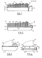
- FIG. 1 shows part of a heat exchanger of a conventional type usable in a motor vehicle, to form the radiator of the cooling circuit of an internal combustion engine.
- the engine coolant flows through the radiator.
- a radiator can be used in the heating or air conditioning installation of the vehicle, or else can be used in a boost circuit, in which case air circulates in the radiator.
- This radiator comprises a bundle 10 of tubes 12 fitted with fins 14, a manifold 16 mounted at one end of the bundle 10 and a water or fluid box 18 mounted on this end of the bundle via the manifold 16.
- the ends of the tubes 12 are mounted in leaktight manner in holes in the manifold 16 and open out inside the water box 18.
- This water box 18 is fixed to the manifold 16 by any suitable means, by example by welding its peripheral rim 20 on the periphery of the collector 16, when the latter is made of plastic, or else by means of crimping lugs which are provided at the periphery of the collector 16 and which are folded over the peripheral rim of the water box 18, when that the collector 16 is metallic.
- the water box 18 is provided with a tube 22 for connection to a heat transfer fluid circuit, this tube can be the inlet tube or the liquid outlet tube in the exchanger.
- this tube can be the inlet tube or the liquid outlet tube in the exchanger.
- the tubing 22 has a bent shape as shown in the drawing, it is very difficult or even impossible to obtain it by molding in one piece with the water box 18. For this reason, the tubing 22 is produced separately and is then fixed to the water box 18, for example by welding its end to the edge of a corresponding orifice in the water box 18.
- the invention proposes, as shown in FIG. 2, to form the tubing at least partly on the manifold.
- the manifold 26 is, as in the prior art, a flat plate comprising holes in which the tubes of the bundle 10 are sealed and further comprises a lateral extension 28, extending in the manifold plane and comprising, by molding, the tubing 30 oriented parallel to the tubes of the bundle 10 and directed in the same direction as the tubing 22 of FIG. 1.
- This tubing has a straight cylindrical shape and can be molded in one piece with the manifold 26, without any difficulty.
- the water box 32 includes, like the manifold 26, a lateral extension 34 which covers the lateral extension 28 of the manifold, so that the tube 30 opens out inside the water box, in the internal volume defined by the lateral extension 34 of the water box and the lateral extension 28 of the collector.
- the water box 32 can be fixed to the collector 26 by welding its peripheral rim 36 to the periphery of the collector 26, when the latter is made of plastic, or else by crimping, by means of pastes provided for the periphery of the collector and which are folded over the peripheral rim 36 of the water box, when the collector is metallic.
- the axis 38 of the tubing is perpendicular to the plane of the manifold 26.
- this axis can be oblique to this plane, if desired.
- the tubing 40 is of variable cross section and comprises an end portion 42 of straight cylindrical shape, connected to the lateral extension 28 of the manifold by a frustoconical portion 44 widening towards the water box 32.
- the axis 46 of the pipe 40 can be perpendicular to the plane of the manifold 26 or oblique to this plane.
- FIG. 4 schematically shows another embodiment of the invention, in which the tube 50 is oriented perpendicular to the direction of the tubes of the bundle 10 and has a variable cross section, which would be impossible to unmold simply or automatically if the tubing was formed in one piece by molding with the water box.
- the manifold 52 comprises a flat part 54 comprising holes in which the ends of the tubes of the bundle are mounted in leaktightness, and a curved lateral edge 56, for example having a substantially semi-cylindrical shape and comprising at its periphery a rim 58 on which is fixed by welding the peripheral rim 60 of a cover 62 having approximately a semi-cylindrical shape, so that the cover 62 and the side edge 56 of the collector constitute the water box itself.
- the lateral edge 56 of the manifold and the cover 62 are formed by molding with semi-ducts 64, 66 respectively, of semi-cylindrical shape, which constitute the cylindrical end of the tube 50 when they are applied one on the 'other along a joint plane which coincides with the joint plane of the flanges 58 and 60 of the manifold and the cover 62 and which passes through the axis 68 of the tube 50.
- the two half-conduits 64 and 66 do not include of external peripheral flanges corresponding to flanges 58 and 60 and which would oppose the watertight mounting of the end of a flexible pipe on the cylindrical end of the tube 50.
- this cylindrical end is connected to a flaring or progressive widening, formed by substantially semi-frustoconical parts 70 and 72 of the manifold 52 and of the cover 62 respectively.
- the axis 68 of the tube 50 could be oblique to the direction of the tubes of the bundle 10 instead of being perpendicular to this direction.
- the invention makes it possible to give any orientation and / or any shape to a fluid inlet or outlet pipe in a fluid box of a heat exchanger, while retaining the possibility of making the box. fluid and the manifold by simple molding operations.
Landscapes
- Engineering & Computer Science (AREA)
- Physics & Mathematics (AREA)
- Thermal Sciences (AREA)
- Mechanical Engineering (AREA)
- General Engineering & Computer Science (AREA)
- Heat-Exchange Devices With Radiators And Conduit Assemblies (AREA)
Abstract
Description
- L'invention concerne un échangeur de chaleur, en particulier pour véhicule automobile, tel par exemple qu'un radiateur monté dans un circuit de liquide de refroidissement d'un moteur à combustion interne ou dans une installation de chauffage ou de climatisation de l'habitacle, ou bien un refroidisseur d'air monté dans un circuit de suralimentation.
- Un tel échangeur comprend en général un corps ou faisceau de tubes et au moins une boîte à fluide qui est montée à une extrémité du corps par l'intermédiaire d'un collecteur ou plaque à trous et qui est reliée à un circuit de fluide par une tubulure.
- La boîte à fluide est le plus souvent réalisée en matière plastique et est moulée en une seule pièce avec sa ou ses tubulures de raccordement au circuit de fluide. La surface interne de chaque tubulure est définie par un noyau ou broche de moulage, que l'on doit pouvoir extraire facilement de façon automatique au démoulage de la boîte à fluide, pour que cette opération soit compatible avec une fabrication en grande série. Il en résulte que les orientations et les formes que l'on peut donner à ces tubulures sont limitées.
- Lorsqu'il faut réaliser une boîte à fluide avec une tubulure qui ne peut être démoulée automatiquement en raison de son orientation et/ou de sa forme, il est nécessaire, soit de prévoir une extraction manuelle des broches ou noyaux de moulage définissant la tubulure, soit de fixer une tubulure indépendante sur un orifice d'une paroi de la boîte à fluide.
- Ces opérations compliquent la fabrication de la boîte à fluide et augmentent son coût.
- L'invention a notamment pour but d'éviter ces inconvénients.
- Elle a essentiellement pour objet, dans un échangeur de chaleur, une boîte à fluide qui peut être munie d'une tubulure dont la forme et/ou l'orientation peuvent être quelconques et sont choisies à volonté.
- L'invention propose à cet effet un échangeur de chaleur, en particulier pour véhicule automobile, comprenant un corps ou faisceau de tubes et au moins une boîte à fluide qui est montée à une extrémité du corps par l'intermédiaire d'un collecteur ou plaque à tubes et qui est reliée à un circuit de fluide par une tubulure, caractérisé en ce qu'au moins une partie de cette tubulure est formée sur le collecteur.
- Selon un premier aspect de l'invention, la tubulure est formée en totalité sur le collecteur.
- Comme celui-ci a en général la forme d'une plaque plane, on peut former la tubulure sur une extension latérale de cette plaque et donner à la tubulure la forme et/ou l'orientation désirées, tout en conservant la possibilité de réaliser le collecteur et la tubulure en une seule opération simple de moulage.
- L'extension latérale du collecteur, qui comprend la tubulure, est alors recouverte par une extension latérale correspondante de la boîte à fluide.
- Selon un deuxième aspect de l'invention, le collecteur est formé avec une moitié de la tubulure, l'autre moitié de cette tubulure étant formée sur la boîte à fluide, et les deux moitiés de la tubulure sont appliquées l'une sur l'autre selon un plan de joint qui passe par l'axe de la tubulure.
- Comme précédemment, on peut donner à cette tubulure une forme et/ou une orientation quelconques, tout en conservant la possibilité d'obtenir le collecteur et la boîte à fluide chacun en une seule opération de moulage.
- Dans la description qui suit, faite à titre d'exemple, on se réfère aux dessins annexés, dans lesquels:
- - la figure 1 est une vue schématique partielle d'un échangeur de chaleur comprenant un collecteur et une boîte à fluide de la technique antérieure;
- - la figure 2 est une vue schématique partielle correspondant à la figure 1, mais représentant un collecteur et une boîte à fluide selon l'invention;
- - la figure 3 est une vue schématique partielle d'une autre forme de réalisation d'un collecteur et d'une boîte à fluide selon l'invention;
- - la figure 4 est une vue schématique partielle d'encore une autre forme de réalisation du collecteur et de la boîte à fluide selon l'invention.
- On se réfère tout d'abord à la figure 1, qui représente une partie d'un échangeur de chaleur d'un type classique utilisable dans un véhicule automobile, pour former le radiateur du circuit de refroidissement d'un moteur à combustion interne. Dans ce cas, le liquide de refroidissement du moteur circule dans le radiateur. Toutefois, un tel radiateur peut être utilisé dans l'installation de chauffage ou de climatisation du véhicule, ou bien peut être utilisé dans un circuit de suralimentation, auquel cas de l'air circule dans le radiateur.
- Ce radiateur comprend un faisceau 10 de tubes 12 munis d'ailettes 14, un collecteur 16 monté à une extrémité du faisceau 10 et une boîte à eau ou à fluide 18 montée sur cette extrémité du faisceau par l'intermédiaire du collecteur 16.
- Comme on le sait, les extrémités des tubes 12 sont montées à étanchéité dans des trous du collecteur 16 et débouchent à l'intérieur de la boîte à eau 18. Cette boîte à eau 18 est fixée sur le collecteur 16 par tout moyen approprié, par exemple par soudure de son rebord périphérique 20 sur la périphérie du collecteur 16, lorsque ce dernier est réalisé en matière plastique, ou bien au moyen de pattes de sertissage qui sont prévues à la périphérie du collecteur 16 et qui sont rabattues sur le rebord périphérique de la boîte à eau 18, lors que le collecteur 16 est métallique.
- Dans l'exemple représenté en figure 1, la boîte à eau 18 est munie d'une tubulure 22 de raccordement à un circuit de fluide caloporteur, cette tubulure pouvant être la tubulure d'entrée ou bien la tubulure de sortie du liquide dans l'échangeur. Lorsque la tubulure 22 a une forme coudée comme représenté sur le dessin, il est très difficile, voire impossible de l'obtenir par moulage en une seule pièce avec la boîte à eau 18. Pour cette raison, la tubulure 22 est réalisée à part et est ensuite fixée sur la boîte à eau 18, par exemple par soudure de son extrémité sur le bord d'un orifice correspondant de la boîte à eau 18.
- Comme indiqué plus haut, il en résulte une complication de la réalisation de l'ensemble boîte eau-tubulure et une augmentation du prix de revient.
- Pour éviter ces inconvénients, l'invention propose comme représenté en figure 2, de former la tubulure au moins en partie sur le collecteur.
- Dans l'exemple de la figure 2, le collecteur 26 est, comme dans la technique antérieure, une plaque plane comprenant des trous dans lesquels sont montés à étanchéité les tubes du faisceau 10 et comprend de plus une extension latérale 28, s'étendant dans le plan du collecteur et comprenant, de moulage, la tubulure 30 orientée parallèlement aux tubes du faisceau 10 et dirigée dans le même sens que la tubulure 22 de la figure 1.
- Cette tubulure a une forme cylindrique droite et peut être moulée en une seule pièce avec le collecteur 26, sans aucune difficulté.
- La boîte à eau 32 comprend, comme le collecteur 26, une extension latérale 34 qui recouvre l'extension latérale 28 du collecteur, de telle sorte que la tubulure 30 débouche à l'intérieur de la boîte à eau, dans le volume interne défini par l'extension latérale 34 de la boîte à eau et l'extension latérale 28 du collecteur.
- Comme précédemment , la boîte à eau 32 peut être fixée sur le collecteur 26 par soudure de son rebord périphérique 36 sur la périphérie du collecteur 26, lorsque celui-ci est réalisé en matière plastique, ou bien par sertissage, au moyen de pates prévues à la périphérie du colecteur et qui sont rabattues sur le rebord périphérique 36 de la boîte à eau, lorsque le collecteur est métallique.
- Dans l'exemple de la figure 2, l'axe 38 de la tubulure est perpendiculaire au plan du collecteur 26. Bien entendu, cet axe peut être oblique par rapport à ce plan, si on le désire.
- Il est également possible, comme représenté en figure 3, de donner à la tubulure une forme particulière, par exemple permettant de réduire les pertes de charge du liquide circulant dans cette tubulure.
- Dans le cas représenté en figure 3, la tubulure 40 est à section transversale variable et comprend une partie d'extrémité 42 de forme cylindrique droite, reliée à l'extension latérale 28 du collecteur par une partie tronconique 44 s'élargissant en direction de la boîte à eau 32.
- Comme dans le cas précédent, l'axe 46 de la tubulure 40 peut être perpendiculaire au plan du collecteur 26 ou oblique par rapport à ce plan.
- La figure 4 présente schématiquement une autre forme de réalisation de l'invention, dans laquelle la tubulure 50 est orientée perpendiculairement à la direction des tubes du faisceau 10 et a une section transversale variable, qui serait impossible à démouler de façon simple ou automatique si la tubulure était formée d'une pièce par moulage avec la boîte à eau.
- Dans ce cas, le collecteur 52 comprend une partie plane 54 comprenant des trous dans lesquels les extrémités des tubes du faisceau sont montées à étanchéité, et une bordure latérale 56 incurvée, ayant par exemple une forme sensiblement semi-cylindrique et comportant à sa périphérie un rebord 58 sur lequel est fixé par soudure le rebord périphérique 60 d'un couvercle 62 ayant approximativement une forme semi-cylindrique, de telle sorte que le couvercle 62 et la bordure latérale 56 du collecteur constituent la boîte à eau proprement dite.
- La bordure latérale 56 du collecteur et le couvercle 62 sont formés de moulage avec des demi-conduits 64, 66 respectivement, de forme semi-cylindrique, qui constituent l'extrémité cylindrique de la tubulure 50 lorsqu'ils sont appliqués l'un sur l'autre selon un plan de joint qui est confondu avec le plan de joint des rebords 58 et 60 du collecteur et du couvercle 62 et qui passe par l'axe 68 de la tubulure 50. Les deux demi-conduits 64 et 66 ne comprennent pas de rebords périphériques externes correspondant aux rebords 58 et 60 et qui s'opposeraient au montage étanche de l'extrémité d'un tuyau souple sur l'extrémité cylindrique de la tubulure 50.
- Comme on le voit en figure 4, cette extrémité cylindrique est raccordée à un évasement ou élargissement progressif, formé par des parties sensiblement semi-tronconiques 70 et 72 respectivement du collecteur 52 et du couvercle 62.
- Comme dans le cas précédent, l'axe 68 de la tubulure 50 pourrait être oblique par rapport à la direction des tubes du faisceau 10 au lieu d'être perpendiculaire à cette direction.
- De façon générale, l'invention permet de donner une orientation et/ou une forme quelconques à une tubulure d'entrée ou de sortie de fluide dans une boîte à fluide d'un échangeur de chaleur, tout en conservant la possibilité de réaliser la boîte à fluide et le collecteur par des opérations simples de moulage.
Claims (10)
Applications Claiming Priority (2)
| Application Number | Priority Date | Filing Date | Title |
|---|---|---|---|
| FR8514685A FR2588365A1 (fr) | 1985-10-03 | 1985-10-03 | Echangeur de chaleur, en particulier pour vehicule automobile |
| FR8514685 | 1985-10-03 |
Publications (2)
| Publication Number | Publication Date |
|---|---|
| EP0222636A1 true EP0222636A1 (fr) | 1987-05-20 |
| EP0222636B1 EP0222636B1 (fr) | 1989-03-22 |
Family
ID=9323507
Family Applications (1)
| Application Number | Title | Priority Date | Filing Date |
|---|---|---|---|
| EP19860402175 Expired EP0222636B1 (fr) | 1985-10-03 | 1986-10-02 | Echangeur de chaleur, en particulier pour véhicule automobile |
Country Status (3)
| Country | Link |
|---|---|
| EP (1) | EP0222636B1 (fr) |
| DE (1) | DE3662561D1 (fr) |
| FR (1) | FR2588365A1 (fr) |
Cited By (7)
| Publication number | Priority date | Publication date | Assignee | Title |
|---|---|---|---|---|
| EP1182414A3 (fr) * | 2000-08-25 | 2003-09-03 | Modine Manufacturing Company | Système de refroidissement |
| EP1182334A3 (fr) * | 2000-08-25 | 2003-10-15 | Modine Manufacturing Company | Aménagement d'échangeur de chaleur |
| US6675879B2 (en) | 2000-09-16 | 2004-01-13 | Modine Manufacturing Company | Compact heat exchanger system |
| US6749007B2 (en) | 2000-08-25 | 2004-06-15 | Modine Manufacturing Company | Compact cooling system with similar flow paths for multiple heat exchangers |
| FR2866419A1 (fr) * | 2004-02-17 | 2005-08-19 | Valeo Climatisation | Boite collectrice munie d'une tubulure de raccordement pour un echangeur de chaleur brase. |
| DE102010025017A1 (de) * | 2010-06-24 | 2011-12-29 | Benteler Automobiltechnik Gmbh | Wärmetauscher |
| EP2128548A3 (fr) * | 2002-06-04 | 2017-11-29 | Valeo Systèmes Thermiques | Echangeur de chaleur à collecteur et boîte collectrice, notamment pour véhicule automobile |
Families Citing this family (5)
| Publication number | Priority date | Publication date | Assignee | Title |
|---|---|---|---|---|
| FR2605727A1 (fr) * | 1986-10-23 | 1988-04-29 | Chausson Usines Sa | Echangeur de chaleur du type dans lequel les tubulures d'amenee et de sortie sont prevues dans une meme boite a eau |
| AT405882B (de) | 1998-02-24 | 1999-12-27 | Pustelnik Werner Dipl Ing | Anschlusseinrichtung für einen flüssigkeitsverteiler |
| FR2844346B1 (fr) * | 2002-09-10 | 2005-05-20 | Valeo Climatisation | Echangeur de chaleur comportant au moins une tubulure de racordement |
| FR2856786B1 (fr) * | 2003-06-26 | 2017-10-27 | Valeo Climatisation | Raccord a section progressive pour un echangeur de chaleur, notamment de vehicule automobile |
| EP1671073B1 (fr) * | 2003-10-02 | 2018-04-11 | MAHLE Behr GmbH & Co. KG | Refroidisseur d'air de suralimentation pour véhicules |
Citations (8)
| Publication number | Priority date | Publication date | Assignee | Title |
|---|---|---|---|---|
| FR703103A (fr) * | 1930-10-02 | 1931-04-25 | Perfectionnement aux systèmes refroidisseurs pour moteurs à combustion | |
| US2814415A (en) * | 1954-07-06 | 1957-11-26 | Griscom Russell Co | Heat exchanger head thermal shield construction |
| US3080915A (en) * | 1959-04-30 | 1963-03-12 | Thomas M Hamill | Heat exchanger |
| FR2148085A1 (fr) * | 1971-07-30 | 1973-03-11 | Daimler Benz Ag | |
| FR2398956A1 (fr) * | 1977-07-25 | 1979-02-23 | Mccord Corp | Joint sans soudure pour echangeur de chaleur |
| FR2526932A1 (fr) * | 1982-05-17 | 1983-11-18 | Valeo | Echangeur de chaleur tel que radiateur de vehicule automobile |
| DE3330101A1 (de) * | 1983-08-20 | 1985-03-07 | Rehau Plastiks Ag + Co, 8673 Rehau | Plattenfoermiger waermetauscher |
| US4520867A (en) * | 1984-02-06 | 1985-06-04 | General Motors Corporation | Single inlet/outlet-tank U-shaped tube heat exchanger |
-
1985
- 1985-10-03 FR FR8514685A patent/FR2588365A1/fr active Pending
-
1986
- 1986-10-02 DE DE8686402175T patent/DE3662561D1/de not_active Expired
- 1986-10-02 EP EP19860402175 patent/EP0222636B1/fr not_active Expired
Patent Citations (8)
| Publication number | Priority date | Publication date | Assignee | Title |
|---|---|---|---|---|
| FR703103A (fr) * | 1930-10-02 | 1931-04-25 | Perfectionnement aux systèmes refroidisseurs pour moteurs à combustion | |
| US2814415A (en) * | 1954-07-06 | 1957-11-26 | Griscom Russell Co | Heat exchanger head thermal shield construction |
| US3080915A (en) * | 1959-04-30 | 1963-03-12 | Thomas M Hamill | Heat exchanger |
| FR2148085A1 (fr) * | 1971-07-30 | 1973-03-11 | Daimler Benz Ag | |
| FR2398956A1 (fr) * | 1977-07-25 | 1979-02-23 | Mccord Corp | Joint sans soudure pour echangeur de chaleur |
| FR2526932A1 (fr) * | 1982-05-17 | 1983-11-18 | Valeo | Echangeur de chaleur tel que radiateur de vehicule automobile |
| DE3330101A1 (de) * | 1983-08-20 | 1985-03-07 | Rehau Plastiks Ag + Co, 8673 Rehau | Plattenfoermiger waermetauscher |
| US4520867A (en) * | 1984-02-06 | 1985-06-04 | General Motors Corporation | Single inlet/outlet-tank U-shaped tube heat exchanger |
Cited By (10)
| Publication number | Priority date | Publication date | Assignee | Title |
|---|---|---|---|---|
| EP1182414A3 (fr) * | 2000-08-25 | 2003-09-03 | Modine Manufacturing Company | Système de refroidissement |
| EP1182334A3 (fr) * | 2000-08-25 | 2003-10-15 | Modine Manufacturing Company | Aménagement d'échangeur de chaleur |
| US6749007B2 (en) | 2000-08-25 | 2004-06-15 | Modine Manufacturing Company | Compact cooling system with similar flow paths for multiple heat exchangers |
| US6779591B2 (en) | 2000-08-25 | 2004-08-24 | Modine Manufacturing Company | Compact heat exchanger for a compact cooling system |
| US6675879B2 (en) | 2000-09-16 | 2004-01-13 | Modine Manufacturing Company | Compact heat exchanger system |
| EP2128548A3 (fr) * | 2002-06-04 | 2017-11-29 | Valeo Systèmes Thermiques | Echangeur de chaleur à collecteur et boîte collectrice, notamment pour véhicule automobile |
| FR2866419A1 (fr) * | 2004-02-17 | 2005-08-19 | Valeo Climatisation | Boite collectrice munie d'une tubulure de raccordement pour un echangeur de chaleur brase. |
| WO2005090892A1 (fr) * | 2004-02-17 | 2005-09-29 | Valeo Systemes Thermiques | Boite collectrice munie d’une tubulure de raccordement pour un echangeur de chaleur brase |
| DE102010025017A1 (de) * | 2010-06-24 | 2011-12-29 | Benteler Automobiltechnik Gmbh | Wärmetauscher |
| DE102010025017B4 (de) | 2010-06-24 | 2018-07-05 | Benteler Automobiltechnik Gmbh | Wärmetauscher |
Also Published As
| Publication number | Publication date |
|---|---|
| DE3662561D1 (en) | 1989-04-27 |
| FR2588365A1 (fr) | 1987-04-10 |
| EP0222636B1 (fr) | 1989-03-22 |
Similar Documents
| Publication | Publication Date | Title |
|---|---|---|
| FR2681421A1 (fr) | Collecteur de raccordement pour un echangeur de chaleur, notamment pour un condenseur de refrigerant. | |
| EP0222636B1 (fr) | Echangeur de chaleur, en particulier pour véhicule automobile | |
| EP1139054B2 (fr) | Ensemble d'une boîte collectrice et d'une tubulure pour échangeur de chaleur | |
| FR2606115A1 (fr) | Vanne a papillon notamment pour vehicule automobile et son application a un carburateur | |
| FR2614980A1 (fr) | Cuve collectrice en matiere plastique pour echangeurs de chaleur a tubes | |
| EP0504034A1 (fr) | Echangeur de chaleur à boîtes à eau reliées pour véhicules automobiles | |
| EP0501855A1 (fr) | Echangeur de chaleur du type à serpentin | |
| FR2766235A1 (fr) | Dispositif de fixation d'un groupe moto-ventilateur sur un element d'un vehicule automobile, notamment un echangeur de chaleur | |
| FR2772905A1 (fr) | Echangeur de chaleur, en particulier refroidisseur d'air de suralimentation, pour vehicule automobile | |
| WO1986005580A1 (fr) | Boite de distribution pour echangeur de chaleur, avec raccord rapide | |
| FR2798992A1 (fr) | Dispositif d'assemblage d'une piece rapportee sur un echangeur de chaleur, en particulier de vehicule automobile | |
| FR2742857A1 (fr) | Plaque collectrice pour echangeur de chaleur | |
| WO1997001059A1 (fr) | Raccord coude pour boite collectrice tubulaire d'un condenseur de climatisation de vehicule | |
| EP0714797B1 (fr) | Boítier pour le logement d'un échangeur de chaleur dans une installation de chauffage et/ou de climatisation d'un véhicule automobile | |
| WO1999030097A1 (fr) | Dispositif pour la fixation d'un conduit d'un premier echangeur de chaleur sur une boite a fluide d'un deuxieme echangeur de chaleur | |
| FR2587468A1 (fr) | Procede pour la liaison entre les tubes et les plaques collectrices d'un echangeur de chaleur et echangeur obtenu par ce procede | |
| FR2577032A1 (fr) | Echangeur de chaleur, notamment pour le chauffage independant du cote conducteur et du cote passager d'un habitacle de voiture de tourisme | |
| FR2755222A1 (fr) | Echangeur de chaleur comportant une boite collectrice a deux compartiments adjacents | |
| WO2016097135A1 (fr) | Échangeur de chaleur comprenant au moins un ensemble d'un faisceau d'échange de chaleur, de deux collecteurs et d'un carter adapte pour recevoir en son sein ledit ensemble | |
| FR2779221A1 (fr) | Ensemble d'echangeurs de chaleur destine a un vehicule automobile | |
| EP0570287B1 (fr) | Dispositif de raccordement de fluide pour un échangeur de chaleur de véhicule automobile | |
| EP0780584A1 (fr) | Dispositif de fixation d'un échangeur de chaleur pour une installation de chauffage et/ou de climatisation de véhicule automobile | |
| FR2825459A1 (fr) | Module d'echange de chaleur comportant un reservoir fixe par l'intermediaire d'une piece de support, et piece de support | |
| EP2128548B1 (fr) | Échangeur de chaleur à collecteur et boîte collectrice, notamment pour véhicule automobile | |
| FR2610395A2 (fr) | Echangeur de chaleur |
Legal Events
| Date | Code | Title | Description |
|---|---|---|---|
| PUAI | Public reference made under article 153(3) epc to a published international application that has entered the european phase |
Free format text: ORIGINAL CODE: 0009012 |
|
| AK | Designated contracting states |
Kind code of ref document: A1 Designated state(s): DE ES GB IT |
|
| 17P | Request for examination filed |
Effective date: 19870928 |
|
| 17Q | First examination report despatched |
Effective date: 19880122 |
|
| GRAA | (expected) grant |
Free format text: ORIGINAL CODE: 0009210 |
|
| AK | Designated contracting states |
Kind code of ref document: B1 Designated state(s): DE ES GB IT |
|
| PG25 | Lapsed in a contracting state [announced via postgrant information from national office to epo] |
Ref country code: IT Free format text: LAPSE BECAUSE OF FAILURE TO SUBMIT A TRANSLATION OF THE DESCRIPTION OR TO PAY THE FEE WITHIN THE PRE;WARNING: LAPSES OF ITALIAN PATENTS WITH EFFECTIVE DATE BEFORE 2007 MAY HAVE OCCURRED AT ANY TIME BEFORE 2007. THE CORRECT EFFECTIVE DATE MAY BE DIFFERENT FROM THE ONE RECORDED.SCRIBED TIME-LIMIT Effective date: 19890322 |
|
| REF | Corresponds to: |
Ref document number: 3662561 Country of ref document: DE Date of ref document: 19890427 |
|
| PG25 | Lapsed in a contracting state [announced via postgrant information from national office to epo] |
Ref country code: ES Free format text: LAPSE BECAUSE OF FAILURE TO SUBMIT A TRANSLATION OF THE DESCRIPTION OR TO PAY THE FEE WITHIN THE PRESCRIBED TIME-LIMIT Effective date: 19890623 |
|
| GBV | Gb: ep patent (uk) treated as always having been void in accordance with gb section 77(7)/1977 [no translation filed] | ||
| PLBI | Opposition filed |
Free format text: ORIGINAL CODE: 0009260 |
|
| PLBI | Opposition filed |
Free format text: ORIGINAL CODE: 0009260 |
|
| PLBI | Opposition filed |
Free format text: ORIGINAL CODE: 0009260 |
|
| 26 | Opposition filed |
Opponent name: KUEHLERFABRIK LAENGERER & REICH GMBH & CO. KG Effective date: 19891130 |
|
| 26 | Opposition filed |
Opponent name: KUEHLERFABRIK LAENGERER & REICH GMBH & CO. KG Effective date: 19891130 Opponent name: SUEDDEUTSCHE KUEHLERFABRIK JULIUS FR. BEHR GMBH & Effective date: 19891208 |
|
| 26 | Opposition filed |
Opponent name: MERCEDES- BENZ AG Effective date: 19891218 Opponent name: KUEHLERFABRIK LAENGERER & REICH GMBH & CO. KG Effective date: 19891130 Opponent name: SUEDDEUTSCHE KUEHLERFABRIK JULIUS FR. BEHR GMBH & Effective date: 19891208 |
|
| PG25 | Lapsed in a contracting state [announced via postgrant information from national office to epo] |
Ref country code: DE Effective date: 19900703 |
|
| PLAB | Opposition data, opponent's data or that of the opponent's representative modified |
Free format text: ORIGINAL CODE: 0009299OPPO |
|
| R26 | Opposition filed (corrected) |
Opponent name: KUEHLERFABRIK LAENGERER & REICH GMBH & CO. KG * 89 Effective date: 19891130 |
|
| RDAG | Patent revoked |
Free format text: ORIGINAL CODE: 0009271 |
|
| STAA | Information on the status of an ep patent application or granted ep patent |
Free format text: STATUS: PATENT REVOKED |
|
| 27W | Patent revoked |
Effective date: 19910125 |
|
| GBPR | Gb: patent revoked under art. 102 of the ep convention designating the uk as contracting state |