EP0222679B1 - Seitenplatte für eine Turbinenscheibe - Google Patents
Seitenplatte für eine Turbinenscheibe Download PDFInfo
- Publication number
- EP0222679B1 EP0222679B1 EP19860630162 EP86630162A EP0222679B1 EP 0222679 B1 EP0222679 B1 EP 0222679B1 EP 19860630162 EP19860630162 EP 19860630162 EP 86630162 A EP86630162 A EP 86630162A EP 0222679 B1 EP0222679 B1 EP 0222679B1
- Authority
- EP
- European Patent Office
- Prior art keywords
- plate
- disk
- slots
- flange
- flanges
- Prior art date
- Legal status (The legal status is an assumption and is not a legal conclusion. Google has not performed a legal analysis and makes no representation as to the accuracy of the status listed.)
- Expired
Links
Images

Classifications
-
- F—MECHANICAL ENGINEERING; LIGHTING; HEATING; WEAPONS; BLASTING
- F01—MACHINES OR ENGINES IN GENERAL; ENGINE PLANTS IN GENERAL; STEAM ENGINES
- F01D—NON-POSITIVE DISPLACEMENT MACHINES OR ENGINES, e.g. STEAM TURBINES
- F01D5/00—Blades; Blade-carrying members; Heating, heat-insulating, cooling or antivibration means on the blades or the members
- F01D5/02—Blade-carrying members, e.g. rotors
- F01D5/08—Heating, heat-insulating or cooling means
- F01D5/081—Cooling fluid being directed on the side of the rotor disc or at the roots of the blades
- F01D5/082—Cooling fluid being directed on the side of the rotor disc or at the roots of the blades on the side of the rotor disc
-
- F—MECHANICAL ENGINEERING; LIGHTING; HEATING; WEAPONS; BLASTING
- F01—MACHINES OR ENGINES IN GENERAL; ENGINE PLANTS IN GENERAL; STEAM ENGINES
- F01D—NON-POSITIVE DISPLACEMENT MACHINES OR ENGINES, e.g. STEAM TURBINES
- F01D5/00—Blades; Blade-carrying members; Heating, heat-insulating, cooling or antivibration means on the blades or the members
- F01D5/30—Fixing blades to rotors; Blade roots ; Blade spacers
- F01D5/3007—Fixing blades to rotors; Blade roots ; Blade spacers of axial insertion type
- F01D5/3015—Fixing blades to rotors; Blade roots ; Blade spacers of axial insertion type with side plates
Definitions
- the invention is a combination seal and sideplate for attachment to a turbine disk and serves as a spaced seal element, a sideplate for the disk to hold the blades in position and to direct cooling air into the blade roots and has its own fastening means to eliminate the need for any bolt attachments of the device to the disk.
- the prior art has generally been an annular seal element carrying several knife-edge seals and bolted to the turbine disk as one element, and a separate plate also bolted to the disk to serve as the sideplate for holding the blades in axial position in the disk and for directing cooling air into the grooves for the blade roots. It has also been necessary to provide additional devices to guide cooling air from the seal element to the separate side plate. This has necessitated another annular device in addition to the many bolts and nuts necessary for holding the several plate elements in position. It is well known that bolt holes create stress concentrations and are undesirable in a high speed device like a turbine disk. The elimination of any bolt holes and bolts as retaining means is a desirable result.
- a turbine rotor assembly having a first annular seal plate and a second cooling fluid distribution and blade root retaining plate is disclosed in US-A-3 010 696.
- GB-A-2 058 945 discloses a turbine rotor assembly according to the precharacterizing portion of claim 1 consisting of a single annular plate for use against the side of the turbine disk having the necessary seal elements near its inner periphery and serving as a sideplate for preventing axial movement of the blade roots within a disk, and also having a means for guiding the cooling air from a point near the axis of the disk outwardly to and into the cooling spaces at the roots of the blades.
- the attachment to the disk by a bayonet form of mount integral with the disk and plate avoids any bolting attachment eliminating the necessity for bolt holes in either disk or plate.
- the turbine rotor assembly according to the invention is characterized by the features recited in the characterizing portion of claim 1.
- the arrangement is also such that the side plate serves as a pump in increasing the cooling air pressure from the point where it is delivered to the side plate near the axis of the disk to the point where it enters the blade roots near to the periphery thereby increasing the flow of air through the bases of the slots in the disk.
- the turbine rotor assembly is shown in conjunction with the first stage disk 10 of a multistage turbine rotor, and this disk has an annular attachment flange 12 extending forwardly and laterally therefrom near or at its center for attachment to the remainder of the rotor. Radially outward from the center of the disk is another lateral flange 14 to support a ring 16 carrying a plurality of knife-edge seals 17 cooperating with a fixed seal ring 18.
- the ring 18 is supported by a fixed structure 20.
- the structure 20 also carries one or more tubes 22 through which cooling air is admitted to the space 24 radially outward from the ring 16 and flange 14.
- the structure 20 also carries another annular seal ring 25 surrounding and in spaced relation to the seal ring 18.
- the ring 16 is secured to the flange 14 by suitable bolts 26.
- the disk has another axially extending flange 27 with an inturned rib 28 on the outer end.
- This inturned rib is notched at 29 so that the rib has evenly spaced elements of projections 30 between the notches and forming part of a bayonet attachment by which to hold a sideplate 32 in position on the disk.
- the plate 32 has an outwardly extending flange 33 to cooperate with the inturned rib, and this outwardly extending flange has a recess 34 to receive the rib 28.
- the flange 33 has notches 36 therein corresponding in dimension to the projection 30 between the notches 29 on the rib 28.
- the notches 36 are spaced apart by projections 38 on the flange 33.
- the plate is held against the disk by the bayonet at attachment which is activated by placing the plate with the projection 38 aligned with the notches 29, moving the plate axially against the disk and then turning the plate to align the notches in the disk and plate thereby placing the projections 38 in alignment with the projections 30 formed by the notches in the flange 27.
- the inner diameter of the rib 28 is the same as the diameter of the bottom of the recess 34 so that there is a tight fit at this location to provide for piloting the plate on the disk and holding these parts in concentric relation.
- the notches 28 are cut deeply into the flange 27, as shown at 42, and the notches 36 are cut to the surface 44, as shown, so that cooling air may pass through the aligned notches to flow along the surface of the disk from the chamber 24 to a chamber 45 radially outward of the flange 27.
- the flange 33 on the plate Radially inward of the flange 33 on the plate, the latter has an inner peripheral extension 46 that extends laterally out of the general plane of the plate and carriers several outwardly extending spaced ribs 48 having on their outer ends knife-edge elements 50 to cooperate with the seal ring 25 above described to minimize air leakage from the chamber 24 at this location.
- the disk 10 Radially outward from the bayonet connection, the disk 10 has an increasing thickness near its periphery to provide adequate dimension for the formation of slots 52 to receive the blade roots 54 therein as in conventional disk constructions. Where the disk becomes thicker, there is an axially extending flange 55 having an inwardly facing axial surface 56, and this axial surface cooperates with another axial surface 58 on a lateral flange 59 on the plate. These cooperating surfaces are nearly the same dimension radially to provide a second pilot for the plate on the disk.
- the preferable embodiment is to have the first pilot at the bayonet connection tight to maintain concentricity between plate and disk and then to adjust the dimension at this outer pilot to tailor the load split between these two locations under different conditions of operation. This is particularly desirable because of the thermal differences between plate and disk during operation, and the significant thermal dimension changes in the respective parts.
- the flanges 55 and 59 have spaced notches 60 and 62 therethrough to allow for a flow of air past these flanges radially outward for cooling the blade roots.
- the plate 32 extends radially outward beyond the flange 59 to overlie the disk between the flange and the blade roots and define a chamber 63 between it and the disk in this area.
- the plate then has a conical portion 64, and the outer periphery of the plate terminates in a radially extending portion 66 that overlies and is held against the surface of the plate and the blade root ends to prevent axial movement of the roots within the disk.
- This radial portion begins is contact with the disk at the outer edge of the conical portion at the point radially outward of the cooling air passages 67 provided at the base of each slot and located at the bottom of the blade root. These passages accept cooling air from the chamber 63 and serve for cooling the disk and the blade root by the flow of the cooling air through the disk.
- the plate 32 has another axial flange 68 on the side remote from the disk and near the conical portion.
- This flange carries at its outer end an outwardly extending rib 70 cooperating with a fixed seal ring 72 adjacent to the disk.
- the plate may have seal grooves 74 and 76 at opposite edges of the radial portion 66 to receive sealing wires 78 and 80. This will provide a tight seal between the plate and disk at these locations and prevent the escape of cooling air past this radial portion of the plate.
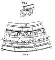
- a modification shown in Fig. 3 may have vanes 82 mounted thereon adjacent to and on the side of the flange 33', and these vanes will serve to increase the pressure rise in the flow of air outwardly between plate and disk to increase the cooling effect on the periphery of the disk.
- These vanes may be integral with the plate, being machined therein, or may be attached thereto if desired. In many installations these vanes are unneccessary, but in particularly high performance turbines they may have added functions in further increasing the pressure of the cooling air as it reaches the slots in a disk.
- the side plate may be locked against turning on the side of the disk by a plurality of slots 84, Fig. 2, in the periphery of the disk or plate 32. These slots are in a position to be engaged by tangs 86 on the blade roots. The tangs and slots are so located that when the tangs engage the slots the projections 30 and 38 are in alignment axially and the slots 60 and 62 are also in alignment. This will assure retention of the side plate securely on the disk.
Landscapes
- Engineering & Computer Science (AREA)
- Mechanical Engineering (AREA)
- General Engineering & Computer Science (AREA)
- Turbine Rotor Nozzle Sealing (AREA)
- Structures Of Non-Positive Displacement Pumps (AREA)
Claims (6)
Applications Claiming Priority (2)
| Application Number | Priority Date | Filing Date | Title |
|---|---|---|---|
| US79480785A | 1985-11-04 | 1985-11-04 | |
| US794807 | 1985-11-04 |
Publications (2)
| Publication Number | Publication Date |
|---|---|
| EP0222679A1 EP0222679A1 (de) | 1987-05-20 |
| EP0222679B1 true EP0222679B1 (de) | 1989-03-15 |
Family
ID=25163739
Family Applications (1)
| Application Number | Title | Priority Date | Filing Date |
|---|---|---|---|
| EP19860630162 Expired EP0222679B1 (de) | 1985-11-04 | 1986-11-04 | Seitenplatte für eine Turbinenscheibe |
Country Status (3)
| Country | Link |
|---|---|
| EP (1) | EP0222679B1 (de) |
| JP (1) | JPS62118033A (de) |
| DE (2) | DE222679T1 (de) |
Cited By (2)
| Publication number | Priority date | Publication date | Assignee | Title |
|---|---|---|---|---|
| RU2614453C1 (ru) * | 2015-12-24 | 2017-03-28 | Открытое акционерное общество "Уфимское моторостроительное производственное объединение" ОАО "УМПО" | Охлаждаемая турбина высокого давления |
| RU2623622C1 (ru) * | 2016-05-12 | 2017-06-28 | Публичное акционерное общество "Уфимское моторостроительное производственное объединение" ПАО "УМПО" | Охлаждаемая турбина высокого давления |
Families Citing this family (15)
| Publication number | Priority date | Publication date | Assignee | Title |
|---|---|---|---|---|
| US4730978A (en) * | 1986-10-28 | 1988-03-15 | United Technologies Corporation | Cooling air manifold for a gas turbine engine |
| FR2666623B1 (fr) * | 1990-09-11 | 1993-05-07 | Turbomeca | Roue de turbomachine a pales rapportees. |
| US6575703B2 (en) * | 2001-07-20 | 2003-06-10 | General Electric Company | Turbine disk side plate |
| EP2011969A1 (de) * | 2007-07-03 | 2009-01-07 | Siemens Aktiengesellschaft | Turbinenanordnung sowie Verfahren zur Befestigung eines Einbauelements |
| US10544677B2 (en) | 2017-09-01 | 2020-01-28 | United Technologies Corporation | Turbine disk |
| FR2940351B1 (fr) * | 2008-12-19 | 2014-11-28 | Snecma | Rotor de turbine d'un moteur a turbine a gaz comprenant un disque de rotor et un flasque d'etancheite |
| FR2961249B1 (fr) * | 2010-06-10 | 2014-05-02 | Snecma | Dispositif de refroidissement des alveoles d'un disque de rotor de turbomachine |
| US8662845B2 (en) | 2011-01-11 | 2014-03-04 | United Technologies Corporation | Multi-function heat shield for a gas turbine engine |
| US8840375B2 (en) | 2011-03-21 | 2014-09-23 | United Technologies Corporation | Component lock for a gas turbine engine |
| FR2982635B1 (fr) * | 2011-11-15 | 2013-11-15 | Snecma | Roue a aubes pour une turbomachine |
| US10641110B2 (en) | 2017-09-01 | 2020-05-05 | United Technologies Corporation | Turbine disk |
| US10724374B2 (en) | 2017-09-01 | 2020-07-28 | Raytheon Technologies Corporation | Turbine disk |
| US10550702B2 (en) | 2017-09-01 | 2020-02-04 | United Technologies Corporation | Turbine disk |
| US10472968B2 (en) * | 2017-09-01 | 2019-11-12 | United Technologies Corporation | Turbine disk |
| CN117532332B (zh) * | 2023-12-12 | 2026-02-10 | 中国航发动力股份有限公司 | 一种小间隙螺栓装配方法 |
Family Cites Families (5)
| Publication number | Priority date | Publication date | Assignee | Title |
|---|---|---|---|---|
| BE551145A (de) * | 1955-09-26 | |||
| US3295825A (en) * | 1965-03-10 | 1967-01-03 | Gen Motors Corp | Multi-stage turbine rotor |
| GB1479332A (en) * | 1974-11-06 | 1977-07-13 | Rolls Royce | Means for retaining blades to a disc or like structure |
| FR2324873A1 (fr) * | 1975-09-17 | 1977-04-15 | Snecma | Perfectionnements aux flasques de rotors de turbomachines |
| US4344740A (en) * | 1979-09-28 | 1982-08-17 | United Technologies Corporation | Rotor assembly |
-
1986
- 1986-11-04 DE DE1986630162 patent/DE222679T1/de active Pending
- 1986-11-04 DE DE8686630162T patent/DE3662420D1/de not_active Expired
- 1986-11-04 EP EP19860630162 patent/EP0222679B1/de not_active Expired
- 1986-11-04 JP JP26260686A patent/JPS62118033A/ja active Pending
Cited By (2)
| Publication number | Priority date | Publication date | Assignee | Title |
|---|---|---|---|---|
| RU2614453C1 (ru) * | 2015-12-24 | 2017-03-28 | Открытое акционерное общество "Уфимское моторостроительное производственное объединение" ОАО "УМПО" | Охлаждаемая турбина высокого давления |
| RU2623622C1 (ru) * | 2016-05-12 | 2017-06-28 | Публичное акционерное общество "Уфимское моторостроительное производственное объединение" ПАО "УМПО" | Охлаждаемая турбина высокого давления |
Also Published As
| Publication number | Publication date |
|---|---|
| JPS62118033A (ja) | 1987-05-29 |
| EP0222679A1 (de) | 1987-05-20 |
| DE222679T1 (de) | 1987-10-15 |
| DE3662420D1 (de) | 1989-04-20 |
Similar Documents
| Publication | Publication Date | Title |
|---|---|---|
| EP0222679A1 (de) | Seitenplatte für eine Turbinenscheibe | |
| US4019833A (en) | Means for retaining blades to a disc or like structure | |
| US4846628A (en) | Rotor assembly for a turbomachine | |
| US3807898A (en) | Bladed rotor assemblies | |
| US4743166A (en) | Blade root seal | |
| US3814539A (en) | Rotor sealing arrangement for an axial flow fluid turbine | |
| US5622475A (en) | Double rabbet rotor blade retention assembly | |
| US3037742A (en) | Compressor turbine | |
| EP0921272B1 (de) | Turbinenrotorscheibenanordnung | |
| US3356340A (en) | Turbine rotor constructions | |
| US4480959A (en) | Device for damping vibrations of mobile turbine blades | |
| EP0134186B1 (de) | Statoranordnung für eine Turbine | |
| EP1211386B1 (de) | Turbinendichtring und entsprechende Turbine | |
| US2985426A (en) | Bladed rotor construction for axialflow fluid machine | |
| EP0161203B1 (de) | Unterstützung einer Turbineneintrittsleitschaufel | |
| US4582467A (en) | Two stage rotor assembly with improved coolant flow | |
| EP1243811B1 (de) | Rotorauswuchtendes System für Turbomaschinen | |
| US4648799A (en) | Cooled combustion turbine blade with retrofit blade seal | |
| US4668167A (en) | Multifunction labyrinth seal support disk for a turbojet engine rotor | |
| US4344740A (en) | Rotor assembly | |
| GB1449415A (en) | Turbine rotor blade cooling and sealing system | |
| US5632598A (en) | Shrouded axial flow turbo machine utilizing multiple labrinth seals | |
| US3023998A (en) | Rotor blade retaining device | |
| EP0210940A1 (de) | Dichtstreifen in Leiterform mit Seitenflanschen | |
| US4747750A (en) | Transition duct seal |
Legal Events
| Date | Code | Title | Description |
|---|---|---|---|
| PUAI | Public reference made under article 153(3) epc to a published international application that has entered the european phase |
Free format text: ORIGINAL CODE: 0009012 |
|
| AK | Designated contracting states |
Kind code of ref document: A1 Designated state(s): DE FR GB |
|
| 17P | Request for examination filed |
Effective date: 19870519 |
|
| EL | Fr: translation of claims filed | ||
| DET | De: translation of patent claims | ||
| 17Q | First examination report despatched |
Effective date: 19871228 |
|
| GRAA | (expected) grant |
Free format text: ORIGINAL CODE: 0009210 |
|
| AK | Designated contracting states |
Kind code of ref document: B1 Designated state(s): DE FR GB |
|
| REF | Corresponds to: |
Ref document number: 3662420 Country of ref document: DE Date of ref document: 19890420 |
|
| ET | Fr: translation filed | ||
| PLBE | No opposition filed within time limit |
Free format text: ORIGINAL CODE: 0009261 |
|
| STAA | Information on the status of an ep patent application or granted ep patent |
Free format text: STATUS: NO OPPOSITION FILED WITHIN TIME LIMIT |
|
| 26N | No opposition filed | ||
| REG | Reference to a national code |
Ref country code: GB Ref legal event code: IF02 |
|
| PGFP | Annual fee paid to national office [announced via postgrant information from national office to epo] |
Ref country code: GB Payment date: 20051004 Year of fee payment: 20 |
|
| PGFP | Annual fee paid to national office [announced via postgrant information from national office to epo] |
Ref country code: FR Payment date: 20051104 Year of fee payment: 20 |
|
| PGFP | Annual fee paid to national office [announced via postgrant information from national office to epo] |
Ref country code: DE Payment date: 20051130 Year of fee payment: 20 |
|
| PG25 | Lapsed in a contracting state [announced via postgrant information from national office to epo] |
Ref country code: GB Free format text: LAPSE BECAUSE OF EXPIRATION OF PROTECTION Effective date: 20061103 |
|
| REG | Reference to a national code |
Ref country code: GB Ref legal event code: PE20 |