EP0222682B1 - Système de transmission de signaux pour un dispositif de protection à comparaison - Google Patents
Système de transmission de signaux pour un dispositif de protection à comparaison Download PDFInfo
- Publication number
- EP0222682B1 EP0222682B1 EP86730150A EP86730150A EP0222682B1 EP 0222682 B1 EP0222682 B1 EP 0222682B1 EP 86730150 A EP86730150 A EP 86730150A EP 86730150 A EP86730150 A EP 86730150A EP 0222682 B1 EP0222682 B1 EP 0222682B1
- Authority
- EP
- European Patent Office
- Prior art keywords
- signal
- frequency signal
- input
- keying
- output
- Prior art date
- Legal status (The legal status is an assumption and is not a legal conclusion. Google has not performed a legal analysis and makes no representation as to the accuracy of the status listed.)
- Expired - Lifetime
Links
- 230000008054 signal transmission Effects 0.000 title claims abstract description 29
- 238000012544 monitoring process Methods 0.000 claims abstract description 58
- 238000011156 evaluation Methods 0.000 claims abstract description 36
- 230000005540 biological transmission Effects 0.000 claims abstract description 25
- 230000011664 signaling Effects 0.000 claims abstract 4
- 230000009849 deactivation Effects 0.000 claims description 2
- 230000001629 suppression Effects 0.000 claims description 2
- 230000010355 oscillation Effects 0.000 description 13
- 230000001681 protective effect Effects 0.000 description 8
- 238000005070 sampling Methods 0.000 description 7
- 230000000052 comparative effect Effects 0.000 description 4
- 238000011144 upstream manufacturing Methods 0.000 description 4
- 230000000903 blocking effect Effects 0.000 description 2
- 238000011161 development Methods 0.000 description 2
- 238000005259 measurement Methods 0.000 description 2
- 230000004913 activation Effects 0.000 description 1
- 230000008901 benefit Effects 0.000 description 1
- 238000001514 detection method Methods 0.000 description 1
- 238000010586 diagram Methods 0.000 description 1
- 238000005516 engineering process Methods 0.000 description 1
- 230000005284 excitation Effects 0.000 description 1
- 238000000034 method Methods 0.000 description 1
- 238000001208 nuclear magnetic resonance pulse sequence Methods 0.000 description 1
- 230000008569 process Effects 0.000 description 1
- 230000007420 reactivation Effects 0.000 description 1
- 230000000717 retained effect Effects 0.000 description 1
- 238000000926 separation method Methods 0.000 description 1
- 238000007493 shaping process Methods 0.000 description 1
- 238000012546 transfer Methods 0.000 description 1
Images


Classifications
-
- H—ELECTRICITY
- H02—GENERATION; CONVERSION OR DISTRIBUTION OF ELECTRIC POWER
- H02H—EMERGENCY PROTECTIVE CIRCUIT ARRANGEMENTS
- H02H7/00—Emergency protective circuit arrangements specially adapted for specific types of electric machines or apparatus or for sectionalised protection of cable or line systems, and effecting automatic switching in the event of an undesired change from normal working conditions
- H02H7/26—Sectionalised protection of cable or line systems, e.g. for disconnecting a section on which a short-circuit, earth fault, or arc discharge has occured
- H02H7/261—Sectionalised protection of cable or line systems, e.g. for disconnecting a section on which a short-circuit, earth fault, or arc discharge has occured involving signal transmission between at least two stations
-
- H—ELECTRICITY
- H02—GENERATION; CONVERSION OR DISTRIBUTION OF ELECTRIC POWER
- H02H—EMERGENCY PROTECTIVE CIRCUIT ARRANGEMENTS
- H02H1/00—Details of emergency protective circuit arrangements
- H02H1/0061—Details of emergency protective circuit arrangements concerning transmission of signals
Definitions
- the invention relates to a signal transmission arrangement for a comparative protection device, in which measured variables are detected in two monitoring stations at two ends of a protective section of an energy transmission system to be monitored, and in each monitoring station a switch-off signal for a switch at the respective end depending on the measured variables detected in both monitoring stations of the protective section is generated with a signal line connecting the two monitoring stations for the transmission of the measured variables or a comparison variable formed from them and with two transmitting / receiving devices, each having a frequency signal generator and a frequency signal receiver with an error signal output and a transmitter, the frequency signal generator being one of the the two transmitting / receiving devices on the output side are connected to one end of the signal line via the associated transmitter and the frequency signal receiver of the other transmitting / receiving device is connected on the input side via the corresponding transmitter to the other end of the signal line.
- the invention is based on the object of specifying a signal transmission arrangement for a comparison protection device with a fault-monitored signal line between two monitoring stations, which enables mutual excitation of both monitoring stations on the basis of a carry signal generated in one of the two monitoring stations or supplied externally to them, without an additional one Signal transmission path is required.
- the relevant frequency signal generator switches the second frequency signal to the signal line with the further keying and keying pause times; the evaluation of the second frequency signal is advantageously prevented in the signal evaluation device of the own frequency signal receiver in that each signal evaluation device has a deactivation input to which the carry signal can be applied.
- the transmission of the driving signal by the one transmitting / receiving device is recognized if the frequency signal received in each case has at least approximately the additional keying and keying pause time specified for the transmission of keying signals.
- the function of monitoring the signal line is also retained in the transmission of carry signals on the signal line, provided that the further scanning pause time of the second frequency signal is shorter than the expiry time of the time lapse stages in the frequency signal receivers of the two transmitting / receiving devices.
- Each clock signal generator advantageously has a function input for suppressing the generation of the first clock signal.
- the two transmitting / receiving devices can be mutually adjusted in such a way that one of the two transmitting / receiving devices feeds the first frequency signal into the signal line for monitoring it and in the respective other transmitting / receiving device the generation of the first frequency signal is switched off via the functional input.
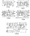
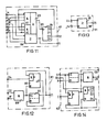
- FIG. 2 The functional blocks shown in FIG. 2 are shown in detail in FIGS. 3 to 14.
- the frequency signal generator 30 contains a sine / square wave generator 35 which outputs a sinusoidal AC voltage of 2 kHz at an output SL and outputs square wave signals derived from the sinusoidal AC voltage at further outputs B0, B1, B2, B4, D0, D1, D2 and D4 .
- a controllable analog switch 36 which switches through the AC voltage supplied to its input SL as a function of a signal at its control input St to the transformer 34.
- the control input St is connected to a correspondingly designated control output of a clock signal generator 37.
- the clock generator 37 is activated in the transmitting / receiving device 15 for emitting the first clock signal, while in the opposite transmitting / receiving device 16 the clock signal generator 37 in question is switched off with respect to the emitting of the first clock signal.
- the clock signal generator 37 is connected at clock inputs B0, DO and D4 to the correspondingly designated outputs of the sine / square wave generator 35.
- the clock signal generator 37 has an additional input EB, via which suppression of the delivery of the first clock signal is possible.
Landscapes
- Physics & Mathematics (AREA)
- Electromagnetism (AREA)
- Selective Calling Equipment (AREA)
- Transmitters (AREA)
- Burglar Alarm Systems (AREA)
- Laying Of Electric Cables Or Lines Outside (AREA)
Claims (8)
Priority Applications (1)
| Application Number | Priority Date | Filing Date | Title |
|---|---|---|---|
| AT86730150T ATE54779T1 (de) | 1985-10-15 | 1986-10-03 | Signaluebertragungsanordnung fuer eine vergleichsschutzeinrichtung. |
Applications Claiming Priority (2)
| Application Number | Priority Date | Filing Date | Title |
|---|---|---|---|
| DE19853537072 DE3537072A1 (de) | 1985-10-15 | 1985-10-15 | Signaluebertragungsanordnung fuer eine vergleichsschutzeinrichtung |
| DE3537072 | 1985-10-15 |
Publications (2)
| Publication Number | Publication Date |
|---|---|
| EP0222682A1 EP0222682A1 (fr) | 1987-05-20 |
| EP0222682B1 true EP0222682B1 (fr) | 1990-07-18 |
Family
ID=6283832
Family Applications (1)
| Application Number | Title | Priority Date | Filing Date |
|---|---|---|---|
| EP86730150A Expired - Lifetime EP0222682B1 (fr) | 1985-10-15 | 1986-10-03 | Système de transmission de signaux pour un dispositif de protection à comparaison |
Country Status (3)
| Country | Link |
|---|---|
| EP (1) | EP0222682B1 (fr) |
| AT (1) | ATE54779T1 (fr) |
| DE (2) | DE3537072A1 (fr) |
Families Citing this family (2)
| Publication number | Priority date | Publication date | Assignee | Title |
|---|---|---|---|---|
| US5793750A (en) * | 1995-10-20 | 1998-08-11 | Schweitzer Engineering Laboratories, Inc. | System of communicating output function status indications between two or more power system protective relays |
| DE10062762A1 (de) | 2000-12-13 | 2002-08-22 | Siemens Ag | Anordnung und Verfahren zur Datenübertragung von digitalen Übertragungsdaten |
-
1985
- 1985-10-15 DE DE19853537072 patent/DE3537072A1/de not_active Withdrawn
-
1986
- 1986-10-03 DE DE8686730150T patent/DE3672755D1/de not_active Expired - Lifetime
- 1986-10-03 AT AT86730150T patent/ATE54779T1/de active
- 1986-10-03 EP EP86730150A patent/EP0222682B1/fr not_active Expired - Lifetime
Also Published As
| Publication number | Publication date |
|---|---|
| DE3672755D1 (de) | 1990-08-23 |
| ATE54779T1 (de) | 1990-08-15 |
| EP0222682A1 (fr) | 1987-05-20 |
| DE3537072A1 (de) | 1987-04-16 |
Similar Documents
| Publication | Publication Date | Title |
|---|---|---|
| EP1058093B1 (fr) | Procédé et circuit d'alimentation et de surveillance du fonctionnement d'au moins un convertisseur de valeurs de mesure | |
| EP0964549B1 (fr) | Circuit de surveillance d'un réseau de transmission | |
| EP0213063A1 (fr) | Circuit pour tester un système de bus passif (méthode d'accès CSMA/CD) | |
| EP0031046B1 (fr) | Dispositif de commande et de surveillance d'appareils électriques à grande sécurité de données | |
| DE2338882C2 (de) | Verfahren und Fernwirksystem zum Ein- und Ausschalten von elektrischen Verbrauchern | |
| DE1513708B2 (de) | Phasenvergleich-schutzanordnung | |
| EP0222682B1 (fr) | Système de transmission de signaux pour un dispositif de protection à comparaison | |
| DE2903860C2 (de) | Einrichtung zur Gleichstromversorgung eines Verbrauchers und zur gleichzeitigen Informationsübertragung über ein Aderpaar | |
| DE2538354A1 (de) | Einrichtung zur funkfernueberwachung von n stationen | |
| DE102009050692B4 (de) | Sicherheits-Kommunikationssystem zur Signalisierung von Systemzuständen | |
| DE2156873B2 (de) | Verfahren und vorrichtung zur fernsteuerung mittels den einzelnen befehlen zugeordneten impulsbildern | |
| EP0598985B1 (fr) | Dispositif de réglage et surveillance d'une section de puissance controlée par un circuit électronique | |
| DE2923716A1 (de) | Verfahren zur uebertragung binaerer signale ueber ein fremdes drahtnetz | |
| DE3882537T2 (de) | Verfahren und Vorrichtung für eine sichere und diagnostizierbare, Signalverwaschungen vermeidende Übertragung. | |
| DE2725152C2 (de) | Überwachungssystem für elektronische Baugruppen oder Geräte in drahtgebundenen Fernmeldeanlagen | |
| DE2134783B2 (de) | Verfahren zur Ermittlung von Fehlern in den mit Regeneratoren versehenen Zwischenstellen eines mit Pulscodemodulation arbeitenden Übertragungssystems | |
| DE3036029C2 (de) | Schaltungsanordnung zur Überwachung einer Verbindungsleitung | |
| DE2719248C2 (de) | Frequenzselektiver Zeichenempfänger für Fernmelde-, insbesondere Fernsprechanlagen | |
| DE1032346B (de) | Fehlermelde- und UEberwachungssystem fuer Funkrelaisstationen von Richtfunkstrecken, insbesondere fuer Mikrowellen-Funkverstaerker | |
| DE3346527A1 (de) | Verfahren und anordnung zur stoerungssicheren alarmauswertung einer meldelinie einer gefahrenmeldeanlage | |
| DE1159033B (de) | Vollelektronische Fernsteuereinrichtung zum Fernsteuern von Zusatzentzerrern fuer Vielkanal-Traegerfrequenz-Weitverkehrssysteme | |
| DE3138650A1 (de) | Verfahren zur ueberwachung einer funkempfangsanlage | |
| DD246089A1 (de) | Schaltungsanordnung zur ueberwachung von achszaehleinrichtungen | |
| EP0178402B1 (fr) | Circuit de surveillance | |
| DE2416523C3 (de) | Anordnung zur fehlersicheren Übertragung von Kommandosignalen |
Legal Events
| Date | Code | Title | Description |
|---|---|---|---|
| PUAI | Public reference made under article 153(3) epc to a published international application that has entered the european phase |
Free format text: ORIGINAL CODE: 0009012 |
|
| AK | Designated contracting states |
Kind code of ref document: A1 Designated state(s): AT BE CH DE FR IT LI NL SE |
|
| 17P | Request for examination filed |
Effective date: 19871027 |
|
| 17Q | First examination report despatched |
Effective date: 19891004 |
|
| GRAA | (expected) grant |
Free format text: ORIGINAL CODE: 0009210 |
|
| AK | Designated contracting states |
Kind code of ref document: B1 Designated state(s): AT BE CH DE FR IT LI NL SE |
|
| PG25 | Lapsed in a contracting state [announced via postgrant information from national office to epo] |
Ref country code: NL Effective date: 19900718 Ref country code: FR Effective date: 19900718 Ref country code: BE Effective date: 19900718 |
|
| REF | Corresponds to: |
Ref document number: 54779 Country of ref document: AT Date of ref document: 19900815 Kind code of ref document: T |
|
| REF | Corresponds to: |
Ref document number: 3672755 Country of ref document: DE Date of ref document: 19900823 |
|
| ITF | It: translation for a ep patent filed | ||
| EN | Fr: translation not filed | ||
| NLV1 | Nl: lapsed or annulled due to failure to fulfill the requirements of art. 29p and 29m of the patents act | ||
| PLBE | No opposition filed within time limit |
Free format text: ORIGINAL CODE: 0009261 |
|
| STAA | Information on the status of an ep patent application or granted ep patent |
Free format text: STATUS: NO OPPOSITION FILED WITHIN TIME LIMIT |
|
| 26N | No opposition filed | ||
| ITTA | It: last paid annual fee | ||
| PGFP | Annual fee paid to national office [announced via postgrant information from national office to epo] |
Ref country code: AT Payment date: 19930929 Year of fee payment: 8 |
|
| PGFP | Annual fee paid to national office [announced via postgrant information from national office to epo] |
Ref country code: SE Payment date: 19940912 Year of fee payment: 9 |
|
| PG25 | Lapsed in a contracting state [announced via postgrant information from national office to epo] |
Ref country code: AT Effective date: 19941003 |
|
| PGFP | Annual fee paid to national office [announced via postgrant information from national office to epo] |
Ref country code: DE Payment date: 19941216 Year of fee payment: 9 |
|
| PGFP | Annual fee paid to national office [announced via postgrant information from national office to epo] |
Ref country code: CH Payment date: 19950118 Year of fee payment: 9 |
|
| EAL | Se: european patent in force in sweden |
Ref document number: 86730150.9 |
|
| PG25 | Lapsed in a contracting state [announced via postgrant information from national office to epo] |
Ref country code: SE Effective date: 19951004 |
|
| PG25 | Lapsed in a contracting state [announced via postgrant information from national office to epo] |
Ref country code: LI Effective date: 19951031 Ref country code: CH Effective date: 19951031 |
|
| REG | Reference to a national code |
Ref country code: CH Ref legal event code: PL |
|
| EUG | Se: european patent has lapsed |
Ref document number: 86730150.9 |
|
| PG25 | Lapsed in a contracting state [announced via postgrant information from national office to epo] |
Ref country code: DE Effective date: 19960702 |
|
| PG25 | Lapsed in a contracting state [announced via postgrant information from national office to epo] |
Ref country code: IT Free format text: LAPSE BECAUSE OF NON-PAYMENT OF DUE FEES;WARNING: LAPSES OF ITALIAN PATENTS WITH EFFECTIVE DATE BEFORE 2007 MAY HAVE OCCURRED AT ANY TIME BEFORE 2007. THE CORRECT EFFECTIVE DATE MAY BE DIFFERENT FROM THE ONE RECORDED. Effective date: 20051003 |