EP0222716A1 - Installation de soudage de tuyaux dans des parois, notamment dans des plaques tubulaires - Google Patents
Installation de soudage de tuyaux dans des parois, notamment dans des plaques tubulaires Download PDFInfo
- Publication number
- EP0222716A1 EP0222716A1 EP86850292A EP86850292A EP0222716A1 EP 0222716 A1 EP0222716 A1 EP 0222716A1 EP 86850292 A EP86850292 A EP 86850292A EP 86850292 A EP86850292 A EP 86850292A EP 0222716 A1 EP0222716 A1 EP 0222716A1
- Authority
- EP
- European Patent Office
- Prior art keywords
- welding
- insert
- housing
- electrode
- lines
- Prior art date
- Legal status (The legal status is an assumption and is not a legal conclusion. Google has not performed a legal analysis and makes no representation as to the accuracy of the status listed.)
- Granted
Links
- 238000003466 welding Methods 0.000 title claims abstract description 108
- 125000006850 spacer group Chemical group 0.000 claims description 12
- 230000001681 protective effect Effects 0.000 claims description 5
- 238000000034 method Methods 0.000 claims description 3
- 238000003780 insertion Methods 0.000 claims 1
- 230000037431 insertion Effects 0.000 claims 1
- 238000012423 maintenance Methods 0.000 abstract description 3
- 230000005540 biological transmission Effects 0.000 abstract 1
- 239000011261 inert gas Substances 0.000 abstract 1
- 239000000498 cooling water Substances 0.000 description 4
- 238000007789 sealing Methods 0.000 description 2
- 239000000725 suspension Substances 0.000 description 2
- 239000000654 additive Substances 0.000 description 1
- 230000000996 additive effect Effects 0.000 description 1
- 239000004020 conductor Substances 0.000 description 1
- 238000010276 construction Methods 0.000 description 1
- 239000002826 coolant Substances 0.000 description 1
- 238000001816 cooling Methods 0.000 description 1
- 238000003825 pressing Methods 0.000 description 1
Images

Classifications
-
- B—PERFORMING OPERATIONS; TRANSPORTING
- B23—MACHINE TOOLS; METAL-WORKING NOT OTHERWISE PROVIDED FOR
- B23K—SOLDERING OR UNSOLDERING; WELDING; CLADDING OR PLATING BY SOLDERING OR WELDING; CUTTING BY APPLYING HEAT LOCALLY, e.g. FLAME CUTTING; WORKING BY LASER BEAM
- B23K9/00—Arc welding or cutting
- B23K9/32—Accessories
- B23K9/323—Combined coupling means, e.g. gas, electricity, water or the like
-
- B—PERFORMING OPERATIONS; TRANSPORTING
- B23—MACHINE TOOLS; METAL-WORKING NOT OTHERWISE PROVIDED FOR
- B23K—SOLDERING OR UNSOLDERING; WELDING; CLADDING OR PLATING BY SOLDERING OR WELDING; CUTTING BY APPLYING HEAT LOCALLY, e.g. FLAME CUTTING; WORKING BY LASER BEAM
- B23K9/00—Arc welding or cutting
- B23K9/02—Seam welding; Backing means; Inserts
- B23K9/028—Seam welding; Backing means; Inserts for curved planar seams
- B23K9/0288—Seam welding; Backing means; Inserts for curved planar seams for welding of tubes to tube plates
Definitions
- the invention relates to a device for welding pipes in walls, especially in tube sheets.
- the device partly comprises a welding device with a fixed housing in which an insert which is rotatable about the longitudinal axis of the welding device is attached, at the end of which is directed towards the welding point, an electrode holder for an electrode is mounted, the tip of which is provided for movement along an essentially circular path is, and partly a control and supply device with lines to the welding machine for the delivery of control signals to a drive mounted in the insert for the rotation of the insert and for the supply of working media, such as electrical energy and protective gas to the electrode.
- a known device for welding pipes in walls is provided with a housing which has a handle, at the free end of which lines for the control and the supply of energy and protective gas are connected.
- An insert is arranged in the housing, which is rotatable about the longitudinal axis of the welding device and carries an electrode at one end.
- the welding machine When operating the welding machine, for example when welding tubes in tube sheets, the working media must be transferred from the lines connected to the fixed housing.
- the welding machine is provided with channels that connect the lines to the insert.
- the invention has for its object to provide a device of the type mentioned, in which a transfer of the working media from the fixed housing to the rotating insert is avoided, and which also has a simple structure, contains few components and is easy to maintain.
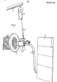
- the welding device 1 clearly shows how a welding device, generally designated 1, according to the invention is used for welding tubes 2 into a wall 3, which can be a tube sheet, for example.
- the welding device 1 has a welding device 4, which can be operated by means of a hose 5 of laid lines is connected to a control and supply device 6 for the emission of control signals and the supply of electrical energy, protective gas, and optionally welding wire and coolant to the welding device.
- the welding device 4 is suspended with a wire rope 7 on a pivotable arm 8 to make work easier for the welder.
- the wire rope 7 hangs from a winch 9 with which the working height of the welding device 4 is adjusted.
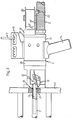
- Fig. 2 the welding of the tube 2 in the wall 3 is shown in more detail.
- the tube 2 and the wall 3 are shown in section.
- a centering member 11 protruding from the welding device 4 is inserted into the tube 2 until a spacer member 12 attached to the end of the welding device 4 facing the wall bears against the wall 3.
- the welding device 4 comprises a fixed housing 13 which is provided with a handle 14 and a suspension eye 15 for the wire rope 7. Parts of the spacer 12 have been broken away in order to make the electrode unit 16 visible, which is attached to an insert which can be rotated about the longitudinal axis of the welding device 4 and which will be described later.
- the electrode unit 16 is guided in a circular path around the centering element 11, an annular weld seam 17 being produced which connects the end of the tube 2 to the wall 3.
- the welding device 4 is provided with an end plate 18 to which the line hose 5 is connected.
- a wire feed unit 19 carries, by means of a bracket 19 ′ attached to the wire feed unit, a coil 20, on which the welding wire 21 is wound.
- the line hose 5 is fastened with the aid of a clip 22.
- the end plate 18 is firmly connected to the insert enclosed by the housing 13 and described below and rotates during the welding process.
- the wire feed mechanism 19 and the line hose 5 make this rotary movement in the same way.
- the spacer 12 is axially adjustable in a manner yet to be described with respect to the housing -13 for setting the arc length. After the adjustment has been carried out, the spacer 12 is fixed with a locking ring 24 serving as a lock nut.
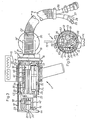
- the welding device 4 is shown in longitudinal section, wherein the centering member 11 is removed.
- the line hose 5 connected to the rotatable end plate 18 contains lines which are connected to the insert which can be rotated about the longitudinal axis of the welding device and is generally designated here by the reference number 25.
- the lines comprise a feed line 26 for the power supply of the drives for the rotation and the wire feed arranged in use and described below and lines for working media, namely a cooling water line 27, a protective gas line 28 and a welding current line 29, which is connected to the electrode 30.
- the welding current line 29 also serves as a return line for the cooling water, as can best be seen in FIG. 5.
- the cooling water flows along the conductor, which effectively cools it.
- the electrode unit 16 is cooled in a known manner by means of cooling water which flows through cooling channels, not shown here. All lines are connected to the control and provision device 6.
- the insert 25 has a cage-like frame 31 which consists of a rear fastening element 32 and a front fastening element 33 which is arranged at a distance therefrom.
- the two elements 32, 33 are connected to one another by means of four rods 34 arranged in the axial direction, as best shown in FIG. 7.
- the rods 34 are terminated at their rear end plate 18 in connection, so that the frame with the end plate 18 forms a non-rotatable unit which is mounted in the housing 13 by means of ball bearings 35.
- a DC motor 36 is fastened to the rear fastening element 32 parallel to the rods 34.
- the motor 36 is provided with a pinion 37 which engages in an internal ring gear 38 which is mounted in the housing.
- the pinion 37 rotates and, as a result of the engagement between pinion 37 and inner ring gear 38, the entire insert 25.
- the insert 25 comprises a pivotable arm in the form of a printed circuit board 39, which is on the rear Fastening element 32 is attached.
- the circuit board 32 has connections 40 on its upper side, to which the control lines 41 of the motor 36 are connected.
- an arm 49 is attached to which a holder 42 is attached.
- the above-mentioned spacer 12 consists of a pipe socket 44, which is provided with openings to expose the view of the weld.
- the pipe socket 44 also serves to adjust the arc length, i.e. of the axial distance between the welding point 10 and the electrode tip 43.
- the pipe socket has an internal thread 45 which interacts with an external thread 46 on the housing 13 of the welding device 4.
- the locking ring 24 which is provided with an internal thread and serves as a counter nut, is screwed onto the rear end of the pipe socket 44.
- the welding wire 21 wound on the coil 20 is advanced through the guide tube 23 of the welding device 4 to the electrode tip 43, as has already been described.
- a welding wire is not required for certain welding work and the wire feed mechanism can then be omitted.
- the welder presses a push button 47, "whereupon the insert 25 and thus the electrode unit 16 makes at least one full rotation during welding and are then automatically turned back to the starting position by the control device.
- the welding device is very easy to operate The effort for the welder is limited to a slight pressing of the welding device 4 suspended at a suitable height against the wall 3.
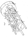
- FIG. 4 shows the structure of the insert 25.
- the elongated circuit board 39 is fastened to the rear fastening element 32 with a screw 48.
- the arm 49 is fastened with screws 50.
- a rack 51 is inserted into a recess 52 of the front fastening element 33 (see FIG. 7).
- a set screw 53 which is provided with a pinion, is screwed into the arm 49 and the pinion is in engagement with the rack 51. If a radial setting of the electrode unit 16 is desired, the adjusting screw 53 is turned. As a result, the arm 49 and the circuit board 39 firmly connected to it are displaced in the radial direction.
- the arm 49 is fixed with a tensioning screw 55 which is provided in an upper slot 54 in the front fastening element 33.
- the electrode unit 16 can be adjusted with a screw 56, which connects the holder 42 to the arm 49.
- the holder is slidable in a slot 57 recessed in the arm 49.
- the front end of the guide tube 23 can be adjusted with the aid of an element 58 which is fastened to the arm with a tensioning screw 60 fitted in a slot 59.
- the guide tube 23 can thus be moved to ensure the desired feed direction of the welding wire 21 with respect to the welding point.
- FIG 4 shows a further DC motor 61, which is attached to the rods 34 of the frame 31 parallel to the axis.
- the motor 61 drives the wire feed mechanism 19 for the welding wire 21.
- the motor 61 like the motor 36, is controlled by a control circuit which is supplied by the feed line 26.
- FIG. 5 shows the mutual arrangement of the parts described above.
- the rods 34 are connected in diametrically arranged grooves 62 to the rear fastening element 32, which is provided with a detachable part 63 with which the lines 27, 28, 29 can be clamped in the fastening element 32. It should be noted that the entire insert 25 with the associated components rotates during the welding process, while the housing 13 with the handle 14 and the suspension eye 15 stands still.
- FIG. 6 shows a variant of the spacer 12 which has three support fingers 64, only two of which are shown.
- the support fingers 64 are fastened with their rear ends in an internally threaded ring 65, which cooperates with an external thread 46 of the housing 13 in the same way as in the previously described pipe socket 44.
- the axial adjustment of the arc length takes place in an analogous manner, with the final Fixed with the locking ring 24.
- the support fingers 64 are used when the pipe 2 protrudes a little on the wall 3 and the pipe socket 44 described above cannot be used.
- FIG. 6 Another form of a holder 66 for the electrode unit 16 is also shown in FIG. 6.
- the holder 66 gives the electrode unit 16 and thus the electrode one other direction, which is particularly advantageous for welding an external fillet.
- the front part 67 of the insert 25 is also shown.
- the front part has an opening to make room for the electrode unit 16, the arm 49, etc.
- a support plate 68 is fastened to the front part 67 with screws 69.
- the screws 69 are screwed into the ends of the rods 34.
- one of the rods 34 only extends to the front fastening element 33 (see FIG. 3).
- Fig. 7 the cage-like frame 31 of the insert 25 is shown, which consists of the end plate 18, the fasteners 32, 33 and the four axial rods 34.
- the end plate 18 has two bores 70, 71 for the implementation of the lines 26, 27, 28, 29 and the welding wire 21 laid in the line hose 5.
- the fastening element 32 has an upper recess 72 for receiving the printed circuit board 39.
- the recess has a threaded hole 73 for a screw for fastening the printed circuit board.
- a bore 74 is provided for the motor 61 of the wire feed unit 19, while a lower recess 75 with a subsequent bore 76 is provided for the motor 36.
- a hole 77 is provided for the electrical lines, which are connected to the circuit board 39.
- the detachable part 63 is fastened to the remaining part of the fastening element 32 and to two rods 34 with screws 79 installed in recesses 78. The screws 79 are accessible from the outside through corresponding openings in the housing 13 (see FIG. 2).
- part 63 is provided with semicircular grooves 80, 81, 82 for lines 27, 28, 29, which are supplemented by corresponding grooves in the remaining fastening element 32 to form bores.
- the lines can thus be clamped in the fastener using part 63 and be solved.
- the front fastening element 33 has an opening 83 in which the arm 49 can be moved.
- the front fastening element 33 has recesses 84, in which screws 85 are arranged for fastening the rods 34.
- the main advantage of the welding device 1 according to the invention is that the use of the welding device 4 can be completely removed from the housing, whereby the maintenance, the replacement of components, etc. is much easier.
- the spacer 12 is unscrewed, then the screws 69 (see FIG. 6) are loosened and the front part 67 is removed. Thereafter, the insert 25 can be easily pulled back out of the housing 13. This disassembly is very easy to do.
- Another significant advantage of the invention is that all of the lines 26, 27, 28, 29 coming from the control and supply device 6 are connected directly to the rotatable insert 25, thereby avoiding the sealing problems which are complicated in the construction of known welding devices of this type Require solutions.
- the lines 26, 27, 28, 29 are guided through the rotatable end plate 18, which is attached outside the housing 13. It is of course also conceivable to use a differently designed end plate, which is attached, for example, within the welding device 4.
- the welding device 1 is excellently suitable for various welding operations, for example for welding internal fillet joints when the pipe end is somewhat inside the wall (see FIG. 2), external fillet joints when the pipe end protrudes somewhat from the wall, including butt joints, if the pipe end is in one plane with the wall.
- the electrode unit 16 is set as it is is appropriate for the current welding operation.
- the welding device 4 has a wire feed mechanism 19.
- the feed mechanism is superfluous. Therefore, the feed mechanism 19 and the guide tube 23 for the welding wire 21 can be removed and can be supplied separately, for example.
- the line hose 5 and thus the lines 26, 27, 28, 29 laid therein should be long enough to avoid twisting.
- the lines between the welding device 4 and the control and supply device 6 should be about 3-10 m long, but can also be considerably longer.
- the welding device is also very suitable for internal welding.
- the welding device is provided with an additive which is inserted into the pipe to be welded and then rotated about its longitudinal axis in order to produce the inner weld seam inside the pipe.
Landscapes
- Engineering & Computer Science (AREA)
- Physics & Mathematics (AREA)
- Plasma & Fusion (AREA)
- Mechanical Engineering (AREA)
- Butt Welding And Welding Of Specific Article (AREA)
- Arc Welding In General (AREA)
- Lining Or Joining Of Plastics Or The Like (AREA)
Priority Applications (1)
| Application Number | Priority Date | Filing Date | Title |
|---|---|---|---|
| AT86850292T ATE62165T1 (de) | 1985-09-11 | 1986-09-08 | Einrichtung fuer das schweissen von rohren in waende, insbesondere in rohrboeden. |
Applications Claiming Priority (2)
| Application Number | Priority Date | Filing Date | Title |
|---|---|---|---|
| SE8504202 | 1985-09-11 | ||
| SE8504202A SE449707B (sv) | 1985-09-11 | 1985-09-11 | Anordning for svetsning av ror i veggar, speciellt tuber i vermevexlargavlar |
Publications (2)
| Publication Number | Publication Date |
|---|---|
| EP0222716A1 true EP0222716A1 (fr) | 1987-05-20 |
| EP0222716B1 EP0222716B1 (fr) | 1991-04-03 |
Family
ID=20361345
Family Applications (1)
| Application Number | Title | Priority Date | Filing Date |
|---|---|---|---|
| EP86850292A Expired - Lifetime EP0222716B1 (fr) | 1985-09-11 | 1986-09-08 | Installation de soudage de tuyaux dans des parois, notamment dans des plaques tubulaires |
Country Status (4)
| Country | Link |
|---|---|
| EP (1) | EP0222716B1 (fr) |
| AT (1) | ATE62165T1 (fr) |
| DE (1) | DE3678531D1 (fr) |
| SE (1) | SE449707B (fr) |
Cited By (2)
| Publication number | Priority date | Publication date | Assignee | Title |
|---|---|---|---|---|
| RU2147271C1 (ru) * | 1999-06-02 | 2000-04-10 | Общевойсковая Академия Вооруженных Сил Российской Федерации | Оборудование для электродуговой сварки танкоремонтной мастерской |
| AT508285A1 (de) * | 2009-05-06 | 2010-12-15 | Fronius Int Gmbh | Anschlusssystem mit einer kupplungsvorrichtung und einem steckelement für einen schweissbrenner |
Citations (2)
| Publication number | Priority date | Publication date | Assignee | Title |
|---|---|---|---|---|
| DE1134464B (de) * | 1956-10-30 | 1962-08-09 | Revere Copper & Brass Inc | Schweisspistole zum Lichtbogenschweissen von Rohren an Rohrwaende |
| AT366612B (de) * | 1980-09-01 | 1982-04-26 | Olaf Reeh Gmbh & Co Apparateba | Verstellbaugruppe des drehbaren schweisskopfes einer elektrischen schweisspistole |
-
1985
- 1985-09-11 SE SE8504202A patent/SE449707B/sv not_active IP Right Cessation
-
1986
- 1986-09-08 EP EP86850292A patent/EP0222716B1/fr not_active Expired - Lifetime
- 1986-09-08 DE DE8686850292T patent/DE3678531D1/de not_active Expired - Lifetime
- 1986-09-08 AT AT86850292T patent/ATE62165T1/de not_active IP Right Cessation
Patent Citations (2)
| Publication number | Priority date | Publication date | Assignee | Title |
|---|---|---|---|---|
| DE1134464B (de) * | 1956-10-30 | 1962-08-09 | Revere Copper & Brass Inc | Schweisspistole zum Lichtbogenschweissen von Rohren an Rohrwaende |
| AT366612B (de) * | 1980-09-01 | 1982-04-26 | Olaf Reeh Gmbh & Co Apparateba | Verstellbaugruppe des drehbaren schweisskopfes einer elektrischen schweisspistole |
Cited By (5)
| Publication number | Priority date | Publication date | Assignee | Title |
|---|---|---|---|---|
| RU2147271C1 (ru) * | 1999-06-02 | 2000-04-10 | Общевойсковая Академия Вооруженных Сил Российской Федерации | Оборудование для электродуговой сварки танкоремонтной мастерской |
| AT508285A1 (de) * | 2009-05-06 | 2010-12-15 | Fronius Int Gmbh | Anschlusssystem mit einer kupplungsvorrichtung und einem steckelement für einen schweissbrenner |
| CN102802859A (zh) * | 2009-05-06 | 2012-11-28 | 弗罗纽斯国际有限公司 | 用于焊炬的包括联接器装置和插塞元件的连接系统 |
| US9040872B2 (en) | 2009-05-06 | 2015-05-26 | Fronius International Gmbh | Connection system comprising a coupling device and a plug element for a welding torch |
| CN102802859B (zh) * | 2009-05-06 | 2016-03-16 | 弗罗纽斯国际有限公司 | 用于焊炬的包括联接器装置和插塞元件的连接系统 |
Also Published As
| Publication number | Publication date |
|---|---|
| SE8504202D0 (sv) | 1985-09-11 |
| DE3678531D1 (de) | 1991-05-08 |
| SE449707B (sv) | 1987-05-18 |
| ATE62165T1 (de) | 1991-04-15 |
| SE8504202L (sv) | 1987-03-12 |
| EP0222716B1 (fr) | 1991-04-03 |
Similar Documents
| Publication | Publication Date | Title |
|---|---|---|
| DE602005003408T2 (de) | Führungsvorrichtung für eine Versorgungsleitung in einem Industrieroboter | |
| DE69709223T2 (de) | Halb-automatische WIG-Schweissvorrichtung | |
| DE2643099A1 (de) | Drahtvorschubeinrichtung zum modulvorschub eines elektrodendrahtes aus grossen entfernungen | |
| DE212010000035U1 (de) | Plasmabrenner-Drehanordnung mit einer Drehbewegung eines inneren Bauteils | |
| WO2013142888A1 (fr) | Partie mâle et partie femelle aux fins de l'assemblage amovible d'un coude de tube d'un chalumeau de soudage refroidi par eau ainsi que dispositif d'assemblage | |
| DE68907077T2 (de) | Bohrvorrichtung. | |
| DE3342684A1 (de) | Automatische schweissmaschine | |
| EP0100465B1 (fr) | Outil pour la réparation des surfaces intérieures usées des pièces de fer | |
| DE2655880C2 (fr) | ||
| DE2338617B2 (de) | Elektrische Widerstandsschweißvorrichtung mit programmgesteuerter drehbarer Schweißeinheit | |
| DE69532138T2 (de) | Tragbare universalbohrmaschine zur durchführung von bohrungen und schweissverteilung in automatischen und semi-automatischen, innerhalb und ausserhalb sackbohrungen und durchgehenden bohrungen | |
| DE2744935C2 (de) | Spulenantriebsvorrichtungen für Rundflechtmaschinen | |
| DE3531039A1 (de) | Anlage mit vorrichtungen zum abnehmen und erneuern von wicklungen elektrischer maschinen | |
| DE7827823U1 (de) | SchweiBvorrichtung | |
| DE2752236A1 (de) | Werkzeugkopf fuer arbeitsmaschinen, insbesondere fuer schweisszangen | |
| EP0222716B1 (fr) | Installation de soudage de tuyaux dans des parois, notamment dans des plaques tubulaires | |
| DE19503648C2 (de) | Vorrichtung zum Einfädeln und Ziehen einer Einziehfeder in elektrische Installationsrohre bzw. aus diesen | |
| DE69300140T2 (de) | Drehmoment-Schraubenschlüssel. | |
| DE1784444C3 (de) | Strahlrohr mit schwenkbarem Mündungsteil | |
| DE202014010178U1 (de) | Hilfshalter und Kraftwerkzeug mit dem selbigen | |
| DE2806871C3 (de) | Widerstandsschweißmaschine | |
| DE60016172T2 (de) | Schweissmaschine | |
| DE19960158C1 (de) | Vorrichtung zum Schälen eines Kabels | |
| EP0211852B1 (fr) | Dispositif de soudage d'un tuyau cylindrique | |
| DE1060071B (de) | Schweisspistole zum Lichtbogenschweissen von Rohren an Rohrwaende |
Legal Events
| Date | Code | Title | Description |
|---|---|---|---|
| PUAI | Public reference made under article 153(3) epc to a published international application that has entered the european phase |
Free format text: ORIGINAL CODE: 0009012 |
|
| AK | Designated contracting states |
Kind code of ref document: A1 Designated state(s): AT BE CH DE FR GB IT LI NL |
|
| ITCL | It: translation for ep claims filed |
Representative=s name: DR. ING. A. RACHELI & C. |
|
| EL | Fr: translation of claims filed | ||
| TCNL | Nl: translation of patent claims filed | ||
| 17P | Request for examination filed |
Effective date: 19871003 |
|
| 17Q | First examination report despatched |
Effective date: 19881031 |
|
| GRAA | (expected) grant |
Free format text: ORIGINAL CODE: 0009210 |
|
| AK | Designated contracting states |
Kind code of ref document: B1 Designated state(s): AT BE CH DE FR GB IT LI NL |
|
| REF | Corresponds to: |
Ref document number: 62165 Country of ref document: AT Date of ref document: 19910415 Kind code of ref document: T |
|
| REF | Corresponds to: |
Ref document number: 3678531 Country of ref document: DE Date of ref document: 19910508 |
|
| ITF | It: translation for a ep patent filed | ||
| ET | Fr: translation filed | ||
| GBT | Gb: translation of ep patent filed (gb section 77(6)(a)/1977) | ||
| PLBE | No opposition filed within time limit |
Free format text: ORIGINAL CODE: 0009261 |
|
| STAA | Information on the status of an ep patent application or granted ep patent |
Free format text: STATUS: NO OPPOSITION FILED WITHIN TIME LIMIT |
|
| 26N | No opposition filed | ||
| PGFP | Annual fee paid to national office [announced via postgrant information from national office to epo] |
Ref country code: BE Payment date: 19990915 Year of fee payment: 14 |
|
| PG25 | Lapsed in a contracting state [announced via postgrant information from national office to epo] |
Ref country code: BE Free format text: LAPSE BECAUSE OF NON-PAYMENT OF DUE FEES Effective date: 20000930 |
|
| BERE | Be: lapsed |
Owner name: ESAB A.B. Effective date: 20000930 |
|
| PGFP | Annual fee paid to national office [announced via postgrant information from national office to epo] |
Ref country code: GB Payment date: 20010810 Year of fee payment: 16 |
|
| PGFP | Annual fee paid to national office [announced via postgrant information from national office to epo] |
Ref country code: AT Payment date: 20010928 Year of fee payment: 16 Ref country code: FR Payment date: 20010928 Year of fee payment: 16 |
|
| PGFP | Annual fee paid to national office [announced via postgrant information from national office to epo] |
Ref country code: NL Payment date: 20010930 Year of fee payment: 16 |
|
| PGFP | Annual fee paid to national office [announced via postgrant information from national office to epo] |
Ref country code: DE Payment date: 20011018 Year of fee payment: 16 |
|
| PGFP | Annual fee paid to national office [announced via postgrant information from national office to epo] |
Ref country code: CH Payment date: 20011221 Year of fee payment: 16 |
|
| REG | Reference to a national code |
Ref country code: GB Ref legal event code: IF02 |
|
| PG25 | Lapsed in a contracting state [announced via postgrant information from national office to epo] |
Ref country code: GB Free format text: LAPSE BECAUSE OF NON-PAYMENT OF DUE FEES Effective date: 20020908 Ref country code: AT Free format text: LAPSE BECAUSE OF NON-PAYMENT OF DUE FEES Effective date: 20020908 |
|
| PG25 | Lapsed in a contracting state [announced via postgrant information from national office to epo] |
Ref country code: LI Free format text: LAPSE BECAUSE OF NON-PAYMENT OF DUE FEES Effective date: 20020930 Ref country code: CH Free format text: LAPSE BECAUSE OF NON-PAYMENT OF DUE FEES Effective date: 20020930 |
|
| PG25 | Lapsed in a contracting state [announced via postgrant information from national office to epo] |
Ref country code: NL Free format text: LAPSE BECAUSE OF NON-PAYMENT OF DUE FEES Effective date: 20030401 Ref country code: DE Free format text: LAPSE BECAUSE OF NON-PAYMENT OF DUE FEES Effective date: 20030401 |
|
| GBPC | Gb: european patent ceased through non-payment of renewal fee |
Effective date: 20020908 |
|
| REG | Reference to a national code |
Ref country code: CH Ref legal event code: PL |
|
| PG25 | Lapsed in a contracting state [announced via postgrant information from national office to epo] |
Ref country code: FR Free format text: LAPSE BECAUSE OF NON-PAYMENT OF DUE FEES Effective date: 20030603 |
|
| REG | Reference to a national code |
Ref country code: FR Ref legal event code: ST |
|
| PG25 | Lapsed in a contracting state [announced via postgrant information from national office to epo] |
Ref country code: IT Free format text: LAPSE BECAUSE OF NON-PAYMENT OF DUE FEES;WARNING: LAPSES OF ITALIAN PATENTS WITH EFFECTIVE DATE BEFORE 2007 MAY HAVE OCCURRED AT ANY TIME BEFORE 2007. THE CORRECT EFFECTIVE DATE MAY BE DIFFERENT FROM THE ONE RECORDED. Effective date: 20050908 |