EP0222734A2 - Presse zum Zusammendrücken von Getränkedosen - Google Patents
Presse zum Zusammendrücken von Getränkedosen Download PDFInfo
- Publication number
- EP0222734A2 EP0222734A2 EP86890300A EP86890300A EP0222734A2 EP 0222734 A2 EP0222734 A2 EP 0222734A2 EP 86890300 A EP86890300 A EP 86890300A EP 86890300 A EP86890300 A EP 86890300A EP 0222734 A2 EP0222734 A2 EP 0222734A2
- Authority
- EP
- European Patent Office
- Prior art keywords
- press
- container
- plunger
- press according
- piston rod
- Prior art date
- Legal status (The legal status is an assumption and is not a legal conclusion. Google has not performed a legal analysis and makes no representation as to the accuracy of the status listed.)
- Granted
Links
Images
Classifications
-
- B—PERFORMING OPERATIONS; TRANSPORTING
- B30—PRESSES
- B30B—PRESSES IN GENERAL
- B30B9/00—Presses specially adapted for particular purposes
- B30B9/32—Presses specially adapted for particular purposes for consolidating scrap metal or for compacting used cars
- B30B9/321—Presses specially adapted for particular purposes for consolidating scrap metal or for compacting used cars for consolidating empty containers, e.g. cans
-
- B—PERFORMING OPERATIONS; TRANSPORTING
- B30—PRESSES
- B30B—PRESSES IN GENERAL
- B30B1/00—Presses, using a press ram, characterised by the features of the drive therefor, pressure being transmitted directly, or through simple thrust or tension members only, to the press ram or platen
- B30B1/02—Presses, using a press ram, characterised by the features of the drive therefor, pressure being transmitted directly, or through simple thrust or tension members only, to the press ram or platen by lever mechanism
- B30B1/04—Presses, using a press ram, characterised by the features of the drive therefor, pressure being transmitted directly, or through simple thrust or tension members only, to the press ram or platen by lever mechanism operated by hand or foot
Definitions
- the invention relates to a press for compressing beverage cans with eccentric force introduction into the beverage can to overcome the dimensional stability.
- the invention aims to provide a press for the daily practical use for compressing beverage cans, which is simple in construction, cheap and reliable and which causes the compression with little effort.
- This is achieved in that an angle lever on a linkage, in particular a tie rod, on the one hand with a foot lever, which is preferably arranged on the lateral surface of a below the press Neten container towered, and on the other hand articulated with a piston rod of a plunger and the piston rod are rigidly connected to the plunger.
- the angle lever With the piston rod rigidly attached to the plunger, the angle lever effects a change in the angular position of the end face of the plunger during the feed movement in the course of the pressing process, and thereby an eccentric introduction of force into the can to be compacted.
- a particularly advantageous embodiment is characterized in that above the press chamber parallel to the longitudinal center axis of the same, an automatically resetting and blocking the movement of the piston, filling shaft flap that swivels into the interior of the press chamber is stored.
- the pedal can only be depressed when the filler flap is closed. It is also expedient if a frame comprising the angle lever, the piston rod and the plunger as well as the baling chamber and the filling shaft flap is arranged on holding brackets lying parallel to one another and if the holding brackets rest on a container for receiving the pressed beverage cans or a sack for the same.
- the brackets can optionally be pivoted together with a lid for the container about an axis provided on the edge of the container. This allows the press to be lifted or swung away when the sack containing the pressed cans is removed.
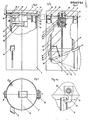
- FIG. 1 shows a top view of a container with a cover and a filling shaft for the press
- FIG. 1 a shows the locking of the container cover
- FIG. 2 shows a front view of the container with a press, partly in section
- FIG. 3 shows a side view, partly in section
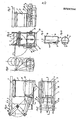
- 4 the press and the sequence of movements in side view
- Fig. 5 the press in plan view
- Fig. 6 the press from the front side in section
- Fig. 7 a detail of the side view according to Fig. 6 the safety bracket in different movement positions
- Fig. 8 the sequence of movements when inserting a beverage can in the press room
- 9 shows the container without a cover with a cover plate for a plastic bag in a partially broken side view
- FIG. 10 shows the container according to FIG. 9 in a top view.
- a container 1 which is proportional to the dimensions of a 0.331 beverage can, is provided as a collecting container for pressed beverage cans, on the upper edge of which a press 3, which is firmly connected to a holding bracket 2, rests.
- a plunger 4 (Fig. 4) is rotatably and longitudinally mounted. The plunger 4 sits rigidly on a piston rod which is connected via an angle lever 5 to a pull rod 8 which in turn is articulated on a foot lever 9.
- the foot lever 9 is mounted on a container support 10 so that it can be rotated vertically with the aid of a bolt 27 fixedly attached to this support; the vertical guidance of the pedal 9 is also supported by a fixedly attached to the right front vessel support 11 foot lever guide bar 12, wherein the length of said foot lever guide bar 12 b the necessary He- elweg corresponds. Also horizontally on the container support 10 is a hook 28, at the front end of which a tension spring 13 is easily detachably connected to the foot lever 9.
- the plastic bag 16 is fastened by means of two, on the upper container ring 14 fixed and horizontally attached bracket 17 each with a holding tip facing the inner wall of the container.
- the container lid 18 (FIG. 1) with the rectangular filling shaft flap 7 attached in the middle of the container lid has four rectangular recesses on its lower edge for receiving the retaining bracket 2, as well as a likewise rectangular recess for receiving a hinge 20 which is fixedly connected to a third container support 19 in order to be flush with the container 1.
- FIG. 1 a The locking of the container lid 18 with the container 1 takes place according to FIG. 1 a by means of a fixedly attached to the lower edge of the inside of the lid ring 30 and with the aid of a hexagon from the outside rotatable hook 21 which engages in a bore of the left, front container support 10.
- a cylindrical pin not visible in the drawings, which is fixedly and vertically attached opposite to the lower edge of the inside of the cover ring 30, fixes its position when the container cover 18 is closed by snapping it into the vertical bore of the right, front container support 11.
- the hinge 20 connects, as shown in Fig. 2, the container lid 18 and the press 3 by means of the bracket 2 rotatably with the container 1, the container lid 18 and the press can be opened individually and keep each other in balance when fully open.
- a securing bracket 24 (FIGS. 6, 7) attached to the left plunger guide 23 prevents the filling shaft 6 from opening by blocking the filling shaft flap part 7 that is not visible.
- the plunger 4 describes during the entire pressing process, a slightly curved path (Fig. 4), the Preßkolben Chemistry 4 constantly inclined at an angle of 0 15'bis 2 remains inclined downwardly, so that the position and shape of the pressure plate 25 and the baffle 22 high compression possible.
- the initially large inclined position of the plunger causes the beverage can to buckle, thereby breaking its dimensional stability.
- the compressed can 31 falls through the rectangular opening (arrow in FIG. 4) left between the pressure plate 25 and the guide plate 22 into the plastic bag 16, and on the other hand the tension spring 13 brings the plunger 4 and the foot lever 9 back to the starting position.
- the safety bracket 24 (FIG. 6) releases the filler flap 7 again.
- the filled plastic bag 16 is removed from the container after the lock 21 has been released, after the container lid 18 has been folded back as far as it will go and the bolt connection 26 between the angle lever 5 and the pull rod 8 has been released, and the press 3 has been folded back with the aid of the holding bracket 2 as far as Fig. 2) and the detachment of the Kunststoffsotffsackes from the brackets 17th
Landscapes
- Engineering & Computer Science (AREA)
- Mechanical Engineering (AREA)
- Jellies, Jams, And Syrups (AREA)
- Tea And Coffee (AREA)
- Processing Of Solid Wastes (AREA)
- Press Drives And Press Lines (AREA)
- Polysaccharides And Polysaccharide Derivatives (AREA)
- Containers Opened By Tearing Frangible Portions (AREA)
- Food Preservation Except Freezing, Refrigeration, And Drying (AREA)
- Supports Or Holders For Household Use (AREA)
Abstract
Description
- Die Erfindung betrifft eine Presse zum Zusammendrücken von Getränkedosen mit exzentrischer Krafteinleitung in die Getränkedose zur Überwindung der Formstabilität.
- Getränkedosen fallen in großen Stückzahlen an und es sind Tendenzen erkennbar, geleerte Dosen im Recycling-Verfahren dem Herstellungsprozeß wieder zuzuführen. Wesentlich dabei ist also, daß die Dosen entgegen ihrer ursprünglichen Bestimmung, ein möglichst großes Volumen zu fassen, beim Rücktransport möglichst wenig Platz erfordern. Es wurden daher Pressen entwickelt, die an Sammelstellen aufgestellt werden und die beispielsweise die Dosen hydraulisch kompaktieren. Eine Presse zum Kompaktieren von Autos ist aus der US-PS 4 188 876 bekannt. Es werden dort Preßplatten hydraulisch um je eine Achse geschwenkt und es wird zusätzlich ein Preßstempel unterhalb der Preßplatten geradlinig ausgeschoben. Mit dem Problem der Kompaktierung von Dosen beschäftigt sich die US-PS 4 213 387. An einem einarmigen schwenkbaren Hebel mit Handgriff ist nahe der Drehachse eine Kolbenstange angelenkt, deren anderes Ende mit einem linear beweglichen Preßkolben in Verbindung steht. Dadurch ergibt sich eine Übersetzung für Betätigung der Presse. Ferner zeigt die US-PS 969 720 eine über eine Kurbelwelle betätigte Presse auf einem Fahrzeug, dessen Räder über eine Kette mit der Kurbelwelle in Verbindung stehen.
- Während eine Presse zum Kompaktieren von Autowracks kaum Gemeinsamkeiten mit einer Dosenpresse hat und von der Gesamtkonzeption für wesentlich größere Kräfte und eine völlig andere Kräfteeinleitung bestimmt ist, erscheint die Hebelpresse nach der US-PS 4 213 387 für die Praxis wenig geeignet zu sein, weil der Kraftaufwand von Hand aus zu groß ist, um eine größere Anzahl von Dosen zu komprimieren.
- Die Erfindung zielt darauf ab, eine Presse für den täglichen praktischen Einsatz zum Komprimieren von Getränkedosen zu schaffen, die einfach im Aufbau, billig und betriebssicher ist und mit wenig Kraftaufwand das Komprimieren bewirkt. Dies wird dadurch erreicht, daß ein Winkelhebel über ein Gestänge,insbesondere eine Zugstange, einerseits mit einem Fußhebel, der vorzugsweise die Mantelfläche eines unterhalb der Presse angeordneten Behälters überragt,und anderseits mit einer Kolbenstange eines Preßkolbens gelenkig und die Kolbenstange mit dem Preßkolben starr verbunden sind. Der Winkelhebel bewirkt mit der starr am Preßkolben befestigten Kolbenstange eine Veränderung der Winkelstellung der Stirnfläche des Preßkolbens während der Vorschubbewegung im Zuge des Preßvorganges und dadurch eine exzentrische Krafteinleitung in die zu kompaktierende Dose. über den Fußhebel lassen sich die erfordelrichen Kräfte spielend leicht aufbringen. Diese Dynamik des exzentrischen Kraftangriffs beim Preßvorgang ist dann besonders vorteilhaft, wenn die Bahnkurve des Anlenkpunktes der Kolbenstange am Winkelhebel die Längsmittelachse des Preßraumes etwa berührt. Dabei ist es besonders zweckmäßig, wenn der Preßkolben stirnseitig eine etwa mittig angeordnete Rippe zur exzentrischen Punktberührung der Getränkedosen aufweist. Um eine irrtümliche Betätigung der Presse mit Pedaldruck bei offenem Pressenraum und damit eine Verletzungsgefahr zu vermeiden, ist eine besonders vorteilhafte Ausführung dadurch gekennzeichnet, daß oberhalb des Preßraumes parallel zur Längsmittelachse desselben eine in das Innere des Preßraumes schwenkbares selbsttätig rückstellende und die Bewegung des Kolbens sperrende Füllschachtklappe gelagert ist. Nur bei geschlossener Füllschachtklappe kann also das Pedal durchgetreten werden. Ferner ist es zweckmäßig, wenn ein dem Winkelhebel, die Kolebenstange und den Preßkolben sowie den Preßraum und die Füllschachtklappe umfassender Rahmen auf parallel zueinander liegenden Haltebügeln angeordnet ist und wenn die Haltebügel auf einem Behälter zur Aufnahme der gepreßten Getränkedosen bzw. eines Sackes für dieselben aufliegen. Es können die Bügel gegebenenfalls zusammen mit einem Deckel für den Behälter um eine randseitig am Behälter vorgesehene Achse schwenkbar sein.Dadurch ist ein Abheben bzw. Wegschwenken der Presse bei Entnahme etwa des die gepreßten Dosen enthaltenden Sackes möglich.
- Ein Ausführungsbeispiel ist in den Zeichnungen dargestellt. Fig. 1 zeigt einen Behälter mit Deckel und Füllschacht für die Presse in Draufsicht, Fig. la die Verriegelung des Behälterdeckels, Fig. 2 eine Frontansicht des Behälters mit Presse, teilweise im Schnitt, Fig. 3 eine Seitenansicht, teilweise im Schnitt, Fig. 4 die Presse und den Bewegungsablauf in Seitenansicht, Fig. 5 die Presse in Draufsicht, Fig. 6 die Presse von der Stirnseite im Schnitt, Fig. 7 ein Detail der Seitenansicht nach Fig. 6 den Sicherungsbügel in unterschiedlichen Bewegungsstellungen, Fig. 8 den Bewegungsablauf beim Einbringen einer Getränkedose in den Pressenraum, Fig. 9 den Behälter ohne Deckel mit Abdeckblech für einen Kunststoffsack in teilweise aufgebrochener Seitenansicht und Fig. 10 den Behälter nach Fig. 9 in Draufsicht.
- Gemäß Fig. 1 bis 3 ist ein in seinen Abmessungen einer 0,331-Getränkedose proportionaler Behälter 1 als Sammelbehälter, für gepreßte Getränkedosen vorgesehen, an dessen oberen Behälterkante eine mit einem Haltebügel 2 fest verbundene Presse 3 aufliegt. In zwei zueinander parallel verlaufenden Langlochführungen des Verdichterkörpers 3 ist ein Preßkolben 4 (Fig. 4) drehbar und längsbeweglich gelagert. Der Preßkolben 4 sitzt starr auf einer Kolbenstange, die über einen Winkelhebel 5 mit einer Zugstange 8 verbunden ist, die ihrerseits an einem Fußhebel 9 angelenkt ist. Der Fußhebel 9 wird gemäß Fig. 3 an einer Behälterstütze 10 mit Hilfe eines an dieser Stütze fix angebrachten Bolzens 27 vertikal drehbar gelagert; die Vertikalführung des Fußhebels 9 wird außerdem durch eine an der rechten, vorderen Behälterstütze 11 fest angebrachten Fußhebel-Führungsleiste 12 unterstützt, wobei die Länge dieser Fußhebel-Führungsleiste 12 dem notwendigen He- belweg entspricht. Ebenfalls an der Behälterstütze 10 ist waagrecht ein Haken 28 aufgebracht, an dessen vorderem Ende eine Zugfeder 13 mit dem Fußhebel 9 leicht lösbar verbunden ist.
- Ein gemäß Fig. 9 in den unteren Behälterring 29 einsteckbares und an den beiden vorderen Behälterstützen 10, 11 einhakbares und daher leicht lösbares Abdeckblech 15 trennt die beweglichen Teile von einem austauschbaren Kunststoffsack 16. Die Befestigung des Kunststoffsackes 16 erfolgt mittels zweier, am oberen Behälterring 14 fest und waagrecht angebrachten Haltebügel 17 mit jeweils einer, der Behälterinnenwand zugewandten Haltespitze.
- Der Behälterdeckel 18 (Fig. 1) mit der in der Behälterdeckelmitte angebrachten, rechteckigen Füllschachtklappe 7, besitzt an seiner unteren Kante vier rechteckige Ausnehmungen zur Aufnahme des Haltebügels 2, sowie eine ebenfalls rechteckige Ausnehmung für die Aufnahme eines mit einer dritten Behälterstütze 19 fest verbundenen Scharniers 20, um mit dem Behälter 1 bündig abzuschließen.
- Die Verriegelung des Behälterdeckels 18 mit dem Behälter 1 erfolgt gemäß Fig. la mittels eines an der unteren Kante der Innenseite des Deckelringes 30 fix angebrachten und mit Hilfe eines Sechskants von außen drehbaren Hakens 21, der in eine Bohrung der linken, vorderen Behälterstütze 10 eingreift. Ein in den Zeichnungen nicht sichtbarer, zylindrischer Stift, der gegenüberliegend an der unteren Kante der Innenseite des Deckelringes 30 fest und senkrecht angebracht ist, fixiert beim Schließen des Behälterdeckels 18 dessen Lage, indem er in die vertikale Bohrung der rechten, vorderen Behälterstütze 11 einrastet.
- Das Scharnier 20 verbindet, wie aus Fig. 2 ersichtlich, den Behälterdeckel 18 und die Presse 3 mit Hilfe des Haltebügels 2 drehbar mit dem Behälter 1, wobei der Behälterdeckel 18 und die Presse einzeln aufklappbar sind und im vollständig geöffneten Zustand einander im Gleichgewicht halten.
- Die Presse arbeitet in folgender Weise:
- Eine Getränkedose 31, beispielsweise aus Aluminium, wird auf die in waagrechter Stellung befindliche Füllschachtklappe 7 des Füllschachtes 6 gelegt (Fig. 1). Durch Niederdrücken der Getränkedose 31 mit einer Hand kippt der sichtbare Teil der durch ein Gegengewicht ausbalancierte Füllschachtklappe 7 (Fig. 6) bis in eine annähernd senkrechte Lage nach unten (Fig. 8), sodaß der Preßraum freigegeben wird. Gleichzeitig aber wird durch das Eindringen der Füllschachtklappe 7 in den Preßraum der Preßkolben 4 in seiner Bewegung gesperrt. Fig. 6 zeigt strichliert die die Kolbenbewegung sperrende Position der Füllschachtklappe. Unmittelbar mit dem Loslassen der Getränkedose 31 schnellt die Füllschachtklappe 7 in die ursprüngliche, waagrechte Lage zurück und gibt damit den Arbeitsbereich der Presse 3 für das Zusammendrücken der Getränkedose 31 frei (Fig. 4). Ein v-förmiges, parallel zur Längskante mittig gebogenes Leitblech 22 (Fig. 6) zwingt die zu verdichtende Getränkedose 31 in die tiefstmögliche, mittige Lage im Preßraum.
- Durch Niederdrücken des Fußhebels 9 (Fig. 3) wird die Fußkraft des Benützers über die Zugstange 8, dem Winkelhebel 5 und der Preßkolbenstirnfläche 4 außermittig und annähernd punktförmig in die Getränkedose 31 eingeleitet (siehe Fig. 4).
- Ab diesem Zeitpunkt verhindert ein an der linken Preßkolbenführung 23 angebrachter Sicherungsbügel 24 (Fig. 6, 7) durch Sperre des nicht sichtbaren Füllschachtklappenteils 7 ein öffnen des Füllschachtes 6.
- Der Preßkolben 4 beschreibt während des gesamten Preßvorganges eine leicht gekrümmte Bahn (Fig., 4), wobei die Preßkolbenfläche 4 ständig in einem Winkel von 15'bis 20 schräg nach unten geneigt bleibt, sodaß Lage und Form der Druckplatte 25 und des Leitblechs 22 eine hohe Verdichtung mitermöglichen. Die vorerst große Schrägstellung des Preßkolbens bewirkt ein Einknicken der Getränkedose und damit ein Brechen ihrer Formstabilität.
- Nach Freigabe des Fußhebels 9 im unteren Anschlagspunkt der Fußhebel-Führungsleiste 12 fällt einerseits die verdichtete Dose 31 durch die zwischen Druckplatte 25 und Leitblech 22 freibleibende, rechteckige öffnung (Pfeil in Fig. 4) in den Kunststoffsack 16, anderseits bringt die Zugfeder 13 den Preßkolben 4 und den Fußhebel 9 in die Ausgangslage zurück. Gleichzeitig gibt der Sicherungsbügel 24 (Fig. 6), die Füllschachtklappe 7 wieder frei.
- Die Herausnahme des gefüllten Kunststoffsackes 16 aus dem Behälter erfolgt nach Lösen der Verriegelung 21, nach Zurückklappen des Behälterdeckels 18 bis zum Anschlag und Lösen der Bolzenverbindung 26 zwischen Winkelhebel 5 und Zugstange 8, sowie Zurückklappen der Presse 3 mit Hilfe des Haltebügels 2 bis zum Anschlag (Fig. 2) und dem Loslösen des Kunstsotffsackes von den Haltebügeln 17.
Claims (7)
Applications Claiming Priority (2)
| Application Number | Priority Date | Filing Date | Title |
|---|---|---|---|
| AT0318385A AT384581B (de) | 1985-11-05 | 1985-11-05 | Presse zum zusammendruecken von getraenkedosen |
| AT3183/85 | 1985-11-05 |
Publications (3)
| Publication Number | Publication Date |
|---|---|
| EP0222734A2 true EP0222734A2 (de) | 1987-05-20 |
| EP0222734A3 EP0222734A3 (en) | 1989-02-15 |
| EP0222734B1 EP0222734B1 (de) | 1991-10-09 |
Family
ID=3546634
Family Applications (1)
| Application Number | Title | Priority Date | Filing Date |
|---|---|---|---|
| EP86890300A Expired - Lifetime EP0222734B1 (de) | 1985-11-05 | 1986-11-05 | Presse zum Zusammendrücken von Getränkedosen |
Country Status (5)
| Country | Link |
|---|---|
| EP (1) | EP0222734B1 (de) |
| AT (2) | AT384581B (de) |
| DE (1) | DE3681882D1 (de) |
| ES (1) | ES2025561T3 (de) |
| GR (1) | GR3002868T3 (de) |
Cited By (4)
| Publication number | Priority date | Publication date | Assignee | Title |
|---|---|---|---|---|
| DE4024048A1 (de) * | 1989-07-31 | 1991-02-07 | Cecil J Stralow | Getraenkedosenzerkleinerungsmaschine |
| GB2245209A (en) * | 1990-06-21 | 1992-01-02 | D J K Packaging Limited | Can crushers |
| US5941167A (en) * | 1997-07-29 | 1999-08-24 | Fleming; James B. | Can crusher |
| CN118150379A (zh) * | 2024-05-09 | 2024-06-07 | 山东高森包装有限公司 | 一种铝制易拉罐轴向承压测试装置 |
Families Citing this family (2)
| Publication number | Priority date | Publication date | Assignee | Title |
|---|---|---|---|---|
| AT396674B (de) * | 1989-07-25 | 1993-11-25 | Troppmann Hubert | Presse zum kompaktieren von hausmüll, insbesondere von dosen oder dergleichen |
| WO2017134315A1 (es) * | 2016-02-01 | 2017-08-10 | Instalaciones Electrodomésticas, S.L. | Dispositivo compactador de envases |
Family Cites Families (7)
| Publication number | Priority date | Publication date | Assignee | Title |
|---|---|---|---|---|
| US2603271A (en) * | 1952-07-15 | Sheets | ||
| US969720A (en) * | 1907-12-04 | 1910-09-06 | Robert F Palmer | Mechanism for crushing cans. |
| US2737995A (en) * | 1954-11-22 | 1956-03-13 | James C Jennings | Oil can crusher |
| US3776129A (en) * | 1972-02-18 | 1973-12-04 | D Carlson | Container crusher |
| US4188876A (en) * | 1976-01-14 | 1980-02-19 | Graves Donald J | Junk metal compressor |
| DE2826207A1 (de) * | 1978-06-15 | 1979-12-20 | Harald Klawe | Vorrichtung zur volumenvermindernden verformung leerer metallischer konservendosen u.dgl. |
| US4213387A (en) * | 1979-05-24 | 1980-07-22 | Bocksruker Ronald W | Can crusher |
-
1985
- 1985-11-05 AT AT0318385A patent/AT384581B/de not_active IP Right Cessation
-
1986
- 1986-11-05 AT AT86890300T patent/ATE68127T1/de not_active IP Right Cessation
- 1986-11-05 ES ES198686890300T patent/ES2025561T3/es not_active Expired - Lifetime
- 1986-11-05 EP EP86890300A patent/EP0222734B1/de not_active Expired - Lifetime
- 1986-11-05 DE DE8686890300T patent/DE3681882D1/de not_active Expired - Lifetime
-
1991
- 1991-10-10 GR GR91401317T patent/GR3002868T3/el unknown
Cited By (6)
| Publication number | Priority date | Publication date | Assignee | Title |
|---|---|---|---|---|
| DE4024048A1 (de) * | 1989-07-31 | 1991-02-07 | Cecil J Stralow | Getraenkedosenzerkleinerungsmaschine |
| DE4024048C2 (de) * | 1989-07-31 | 1999-04-01 | Cecil J Stralow | Getränkedosenpresse |
| GB2245209A (en) * | 1990-06-21 | 1992-01-02 | D J K Packaging Limited | Can crushers |
| GB2245209B (en) * | 1990-06-21 | 1994-08-24 | D J K Packaging Limited | Crushers |
| US5941167A (en) * | 1997-07-29 | 1999-08-24 | Fleming; James B. | Can crusher |
| CN118150379A (zh) * | 2024-05-09 | 2024-06-07 | 山东高森包装有限公司 | 一种铝制易拉罐轴向承压测试装置 |
Also Published As
| Publication number | Publication date |
|---|---|
| ATA318385A (de) | 1987-05-15 |
| ATE68127T1 (de) | 1991-10-15 |
| GR3002868T3 (en) | 1993-01-25 |
| DE3681882D1 (de) | 1991-11-14 |
| ES2025561T3 (es) | 1992-04-01 |
| EP0222734B1 (de) | 1991-10-09 |
| AT384581B (de) | 1987-12-10 |
| EP0222734A3 (en) | 1989-02-15 |
Similar Documents
| Publication | Publication Date | Title |
|---|---|---|
| EP0336003A2 (de) | Müllsammelfahrzeug | |
| DE2162189C3 (de) | Gerät zum Zusammendrücken von MOU | |
| DE2344698C2 (de) | Vorrichtung zum Verdichten von Müll | |
| EP0222734B1 (de) | Presse zum Zusammendrücken von Getränkedosen | |
| DE3332451A1 (de) | Maschine zum zusammendruecken von zylindrischen aluminiumdosen fuer bier, alkoholfreie getraenke, etc. | |
| DE10251516B4 (de) | Ballenpresse | |
| AT402047B (de) | Behälter | |
| DE4237143A1 (en) | Compactor for refuse in refuse skip - has swinging panel with flap which is retracted on up-stroke of panel | |
| DE2944307A1 (de) | Muellpresse | |
| DE8229130U1 (de) | Vorrichtung zum Abstellen und Festlegen von transportfaehigen Sammelbehaeltern insbesondere Abfall-bzw Muellbehaeltern | |
| AT396674B (de) | Presse zum kompaktieren von hausmüll, insbesondere von dosen oder dergleichen | |
| DE1173837B (de) | Muellsammelbehaelter | |
| DE2656549A1 (de) | Deckel fuer abfallbehaelter | |
| EP1171283B1 (de) | Ballenpresse mit kippbarem presskasten sowie verfahren zur betätigung selbiger | |
| DE10004057C2 (de) | Wertstoffsammler | |
| DE2064581C3 (de) | Vorrichtung an Gefäßen zur Aufnahme von Gut, insbesondere von Müll, mit einer Preßvorrichtung | |
| DE9414479U1 (de) | Hubvorrichtung für ein in ein Entsorgungsfahrzeug zu entleerendes Müll- und/oder Wertstoff-Gefäß | |
| DE2553662A1 (de) | Pressvorrichtung fuer muelltonnen | |
| DE2625371A1 (de) | Vorrichtung zum verdichten von muell | |
| DE9401138U1 (de) | Ballenpresse | |
| DE7903457U1 (de) | Vorrichtung zur verbesserung der ausnutzung des innenraumes von muellbehaeltern | |
| DE9004989U1 (de) | Ballenpresse | |
| DE2448072C3 (de) | Müllbehälter mit einer Vorrichtung zum Verdichten von Müll | |
| DE2145925A1 (de) | Muellpresse | |
| DE2030915C3 (de) | Vorrichtung zum Pressen von paketfähigen losen Gut, insbesondere Müll |
Legal Events
| Date | Code | Title | Description |
|---|---|---|---|
| PUAI | Public reference made under article 153(3) epc to a published international application that has entered the european phase |
Free format text: ORIGINAL CODE: 0009012 |
|
| AK | Designated contracting states |
Kind code of ref document: A2 Designated state(s): AT BE CH DE ES FR GB GR IT LI LU NL SE |
|
| PUAL | Search report despatched |
Free format text: ORIGINAL CODE: 0009013 |
|
| AK | Designated contracting states |
Kind code of ref document: A3 Designated state(s): AT BE CH DE ES FR GB GR IT LI LU NL SE |
|
| 17P | Request for examination filed |
Effective date: 19890427 |
|
| 17Q | First examination report despatched |
Effective date: 19900621 |
|
| GRAA | (expected) grant |
Free format text: ORIGINAL CODE: 0009210 |
|
| AK | Designated contracting states |
Kind code of ref document: B1 Designated state(s): AT BE CH DE ES FR GB GR IT LI LU NL SE |
|
| REF | Corresponds to: |
Ref document number: 68127 Country of ref document: AT Date of ref document: 19911015 Kind code of ref document: T |
|
| ET | Fr: translation filed | ||
| PG25 | Lapsed in a contracting state [announced via postgrant information from national office to epo] |
Ref country code: AT Effective date: 19911105 |
|
| GBT | Gb: translation of ep patent filed (gb section 77(6)(a)/1977) | ||
| REF | Corresponds to: |
Ref document number: 3681882 Country of ref document: DE Date of ref document: 19911114 |
|
| ITF | It: translation for a ep patent filed | ||
| REG | Reference to a national code |
Ref country code: ES Ref legal event code: FG2A Ref document number: 2025561 Country of ref document: ES Kind code of ref document: T3 |
|
| PLBE | No opposition filed within time limit |
Free format text: ORIGINAL CODE: 0009261 |
|
| STAA | Information on the status of an ep patent application or granted ep patent |
Free format text: STATUS: NO OPPOSITION FILED WITHIN TIME LIMIT |
|
| 26N | No opposition filed | ||
| REG | Reference to a national code |
Ref country code: GR Ref legal event code: FG4A Free format text: 3002868 |
|
| PGFP | Annual fee paid to national office [announced via postgrant information from national office to epo] |
Ref country code: SE Payment date: 19921111 Year of fee payment: 7 Ref country code: LU Payment date: 19921111 Year of fee payment: 7 |
|
| PGFP | Annual fee paid to national office [announced via postgrant information from national office to epo] |
Ref country code: BE Payment date: 19921124 Year of fee payment: 7 |
|
| EPTA | Lu: last paid annual fee | ||
| PGFP | Annual fee paid to national office [announced via postgrant information from national office to epo] |
Ref country code: GR Payment date: 19931027 Year of fee payment: 8 |
|
| PGFP | Annual fee paid to national office [announced via postgrant information from national office to epo] |
Ref country code: GB Payment date: 19931029 Year of fee payment: 8 Ref country code: FR Payment date: 19931029 Year of fee payment: 8 |
|
| PG25 | Lapsed in a contracting state [announced via postgrant information from national office to epo] |
Ref country code: LU Free format text: LAPSE BECAUSE OF NON-PAYMENT OF DUE FEES Effective date: 19931105 |
|
| PG25 | Lapsed in a contracting state [announced via postgrant information from national office to epo] |
Ref country code: SE Effective date: 19931106 |
|
| PGFP | Annual fee paid to national office [announced via postgrant information from national office to epo] |
Ref country code: ES Payment date: 19931115 Year of fee payment: 8 |
|
| PG25 | Lapsed in a contracting state [announced via postgrant information from national office to epo] |
Ref country code: BE Effective date: 19931130 |
|
| PGFP | Annual fee paid to national office [announced via postgrant information from national office to epo] |
Ref country code: NL Payment date: 19931130 Year of fee payment: 8 |
|
| PGFP | Annual fee paid to national office [announced via postgrant information from national office to epo] |
Ref country code: DE Payment date: 19931230 Year of fee payment: 8 |
|
| PGFP | Annual fee paid to national office [announced via postgrant information from national office to epo] |
Ref country code: CH Payment date: 19940215 Year of fee payment: 8 |
|
| BERE | Be: lapsed |
Owner name: TROPPMANN HUBERT Effective date: 19931130 |
|
| PG25 | Lapsed in a contracting state [announced via postgrant information from national office to epo] |
Ref country code: GB Effective date: 19941105 |
|
| PG25 | Lapsed in a contracting state [announced via postgrant information from national office to epo] |
Ref country code: ES Free format text: LAPSE BECAUSE OF THE APPLICANT RENOUNCES Effective date: 19941107 |
|
| PG25 | Lapsed in a contracting state [announced via postgrant information from national office to epo] |
Ref country code: LI Effective date: 19941130 Ref country code: CH Effective date: 19941130 |
|
| EUG | Se: european patent has lapsed |
Ref document number: 86890300.6 Effective date: 19940610 |
|
| PG25 | Lapsed in a contracting state [announced via postgrant information from national office to epo] |
Ref country code: GR Free format text: THE PATENT HAS BEEN ANNULLED BY A DECISION OF A NATIONAL AUTHORITY Effective date: 19950531 |
|
| PG25 | Lapsed in a contracting state [announced via postgrant information from national office to epo] |
Ref country code: NL Effective date: 19950601 |
|
| GBPC | Gb: european patent ceased through non-payment of renewal fee |
Effective date: 19941105 |
|
| NLV4 | Nl: lapsed or anulled due to non-payment of the annual fee | ||
| PG25 | Lapsed in a contracting state [announced via postgrant information from national office to epo] |
Ref country code: FR Effective date: 19950731 |
|
| REG | Reference to a national code |
Ref country code: CH Ref legal event code: PL Ref country code: GR Ref legal event code: MM2A Free format text: 3002868 |
|
| PG25 | Lapsed in a contracting state [announced via postgrant information from national office to epo] |
Ref country code: DE Effective date: 19950801 |
|
| REG | Reference to a national code |
Ref country code: FR Ref legal event code: ST |
|
| REG | Reference to a national code |
Ref country code: ES Ref legal event code: FD2A Effective date: 20010402 |
|
| PG25 | Lapsed in a contracting state [announced via postgrant information from national office to epo] |
Ref country code: IT Free format text: LAPSE BECAUSE OF NON-PAYMENT OF DUE FEES;WARNING: LAPSES OF ITALIAN PATENTS WITH EFFECTIVE DATE BEFORE 2007 MAY HAVE OCCURRED AT ANY TIME BEFORE 2007. THE CORRECT EFFECTIVE DATE MAY BE DIFFERENT FROM THE ONE RECORDED. Effective date: 20051105 |