EP0222741B1 - Systeme de mesure de l'epaisseur pour materiau en feuilles - Google Patents
Systeme de mesure de l'epaisseur pour materiau en feuilles Download PDFInfo
- Publication number
- EP0222741B1 EP0222741B1 EP85902030A EP85902030A EP0222741B1 EP 0222741 B1 EP0222741 B1 EP 0222741B1 EP 85902030 A EP85902030 A EP 85902030A EP 85902030 A EP85902030 A EP 85902030A EP 0222741 B1 EP0222741 B1 EP 0222741B1
- Authority
- EP
- European Patent Office
- Prior art keywords
- force
- measuring
- release
- spring
- measuring gap
- Prior art date
- Legal status (The legal status is an assumption and is not a legal conclusion. Google has not performed a legal analysis and makes no representation as to the accuracy of the status listed.)
- Expired
Links
- 238000005259 measurement Methods 0.000 title claims abstract description 13
- 239000000463 material Substances 0.000 title abstract description 27
- 239000011888 foil Substances 0.000 title abstract 2
- 230000001419 dependent effect Effects 0.000 claims description 4
- 230000007246 mechanism Effects 0.000 abstract description 4
- 238000012360 testing method Methods 0.000 description 22
- 229910000831 Steel Inorganic materials 0.000 description 8
- 239000010959 steel Substances 0.000 description 8
- 230000000903 blocking effect Effects 0.000 description 6
- 230000015572 biosynthetic process Effects 0.000 description 4
- 239000013078 crystal Substances 0.000 description 3
- 208000027744 congestion Diseases 0.000 description 2
- 230000001960 triggered effect Effects 0.000 description 2
- 230000005856 abnormality Effects 0.000 description 1
- 230000006978 adaptation Effects 0.000 description 1
- 230000008859 change Effects 0.000 description 1
- 239000011093 chipboard Substances 0.000 description 1
- 230000008878 coupling Effects 0.000 description 1
- 238000010168 coupling process Methods 0.000 description 1
- 238000005859 coupling reaction Methods 0.000 description 1
- 238000001514 detection method Methods 0.000 description 1
- 238000011161 development Methods 0.000 description 1
- 238000011156 evaluation Methods 0.000 description 1
- 230000007257 malfunction Effects 0.000 description 1
- 238000000034 method Methods 0.000 description 1
- 239000000123 paper Substances 0.000 description 1
- 230000008569 process Effects 0.000 description 1
- 230000001681 protective effect Effects 0.000 description 1
- 239000010453 quartz Substances 0.000 description 1
- VYPSYNLAJGMNEJ-UHFFFAOYSA-N silicon dioxide Inorganic materials O=[Si]=O VYPSYNLAJGMNEJ-UHFFFAOYSA-N 0.000 description 1
- 230000003068 static effect Effects 0.000 description 1
Images

Classifications
-
- G—PHYSICS
- G01—MEASURING; TESTING
- G01B—MEASURING LENGTH, THICKNESS OR SIMILAR LINEAR DIMENSIONS; MEASURING ANGLES; MEASURING AREAS; MEASURING IRREGULARITIES OF SURFACES OR CONTOURS
- G01B21/00—Measuring arrangements or details thereof, where the measuring technique is not covered by the other groups of this subclass, unspecified or not relevant
- G01B21/02—Measuring arrangements or details thereof, where the measuring technique is not covered by the other groups of this subclass, unspecified or not relevant for measuring length, width, or thickness
- G01B21/08—Measuring arrangements or details thereof, where the measuring technique is not covered by the other groups of this subclass, unspecified or not relevant for measuring length, width, or thickness for measuring thickness
-
- G—PHYSICS
- G01—MEASURING; TESTING
- G01B—MEASURING LENGTH, THICKNESS OR SIMILAR LINEAR DIMENSIONS; MEASURING ANGLES; MEASURING AREAS; MEASURING IRREGULARITIES OF SURFACES OR CONTOURS
- G01B5/00—Measuring arrangements characterised by the use of mechanical techniques
- G01B5/02—Measuring arrangements characterised by the use of mechanical techniques for measuring length, width or thickness
- G01B5/06—Measuring arrangements characterised by the use of mechanical techniques for measuring length, width or thickness for measuring thickness
- G01B5/068—Measuring arrangements characterised by the use of mechanical techniques for measuring length, width or thickness for measuring thickness of objects while moving
-
- G—PHYSICS
- G01—MEASURING; TESTING
- G01B—MEASURING LENGTH, THICKNESS OR SIMILAR LINEAR DIMENSIONS; MEASURING ANGLES; MEASURING AREAS; MEASURING IRREGULARITIES OF SURFACES OR CONTOURS
- G01B7/00—Measuring arrangements characterised by the use of electric or magnetic techniques
- G01B7/02—Measuring arrangements characterised by the use of electric or magnetic techniques for measuring length, width or thickness
- G01B7/06—Measuring arrangements characterised by the use of electric or magnetic techniques for measuring length, width or thickness for measuring thickness
- G01B7/063—Measuring arrangements characterised by the use of electric or magnetic techniques for measuring length, width or thickness for measuring thickness using piezoelectric resonators
-
- G—PHYSICS
- G07—CHECKING-DEVICES
- G07D—HANDLING OF COINS OR VALUABLE PAPERS, e.g. TESTING, SORTING BY DENOMINATIONS, COUNTING, DISPENSING, CHANGING OR DEPOSITING
- G07D7/00—Testing specially adapted to determine the identity or genuineness of valuable papers or for segregating those which are unacceptable, e.g. banknotes that are alien to a currency
- G07D7/16—Testing the dimensions
- G07D7/164—Thickness
-
- G—PHYSICS
- G07—CHECKING-DEVICES
- G07D—HANDLING OF COINS OR VALUABLE PAPERS, e.g. TESTING, SORTING BY DENOMINATIONS, COUNTING, DISPENSING, CHANGING OR DEPOSITING
- G07D7/00—Testing specially adapted to determine the identity or genuineness of valuable papers or for segregating those which are unacceptable, e.g. banknotes that are alien to a currency
- G07D7/181—Testing mechanical properties or condition, e.g. wear or tear
- G07D7/183—Detecting folds or doubles
Definitions
- Device for the contacting measurement of thickness differences on sheet material which is fed to the device with the aid of a transport system, with a measuring gap provided in the transport plane, which by means of an abutment rigidly arranged with respect to the measuring gap and a first deflectable perpendicular to the sheet material in relation to the measuring gap Scanning element is formed.
- a thickness measuring device for the mechanical thickness measurement of chipboard is known. Differences in the thickness of the material to be measured are measured in a measuring gap between a sensor in the form of a scanning roller and a rigid plate support.
- the scanning roller is connected to a rod which is guided in a first cylinder piston arrangement (measuring cylinder) so that it can be moved up and down.
- the geometry of the measuring cylinder is designed so that the piston can take up the measuring stroke against an air cushion.
- a second cylinder piston arrangement (adjusting cylinder) is mechanically rigidly coupled to the first, with the task of performing the zero adjustment of the device or adjusting the measuring system to the expected thickness "d" of the material to be measured.
- the pressure in the adjusting cylinder is very high compared to that in the measuring cylinder, so that the thickness differences in the tolerance range d ⁇ Ad caused by the material to be measured can be absorbed by the measuring cylinder unaffected by movements of the adjusting cylinder. If excess thicknesses occur in the measuring gap that exceed the tolerances of ⁇ Ad, the permissible working range is exceeded in the measuring cylinder and the forces resulting from the excess thickness are transferred to the cylinder piston arrangement which now acts as a rigid abutment. Since no measures are provided to protect the thickness measuring device against excess thickness, damage or misalignments inevitably occur on the measuring system.
- the contacting thickness measurement is problematic insofar as the necessary measuring speeds are much higher there and the material to be measured is transported through the measuring device in a much faster sequence and the differences in thickness to be measured are significantly smaller.
- Some of these abnormalities are a multiple of the "standard thickness". They easily lead to the formation of jams in the transport system as well as damage or misalignments to the measuring system. Since the malfunctions in most cases have to be remedied manually, the throughput of the document sorting machine may be greatly reduced.
- the invention is therefore based on the object to propose a device for the contact measurement of thickness differences on sheet material, which the above. Avoids disadvantages.
- the basic idea of the invention is to provide a pre-test scanning element in front of the actual measuring gap, which preferably forms a pre-test measuring gap together with the abutment of the first scanning element, the pre-test scanning element reacting to excessive thickness of the transported material and, if necessary, the measuring system the transport level swings away.
- the pre-test sensing element which detects the excess thickness and is even insensitive to mechanical influences, absorbs the forces caused by excess thickness and uses it to swing the measuring system away, so that the formation of jams in the transport system and damage and misalignment of the measuring system are avoided.
- An abutment interacting with the scanning elements is preferably a steel roller, which is also an element of the transport system.
- the pivoting away of the measuring device is only triggered when a certain, adjustable force acts on the pre-test scanning element.
- the pre-test scanning element is connected to a trigger mechanism which rigidly couples the measuring system to the steel roller forming the abutment in the permissible working range.
- the function of the second abutment is canceled when the force acting on the pre-test scanning element exceeds the predetermined force set on the trigger mechanism.
- the trigger mechanism is preferably designed such that the measuring system is automatically returned to the original position as soon as the excess thickness causing the deflection has passed the measuring system. This eliminates the need for manual intervention to eliminate accidents.
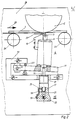
- FIG. 1 shows, in an exemplary embodiment, a thickness measuring device according to the invention.
- the essential elements of the device are the measuring device 4, the triggering device 15, the transport system 24, 25, 3 with integrated abutment 2 and the pre-test scanning element 10.
- the measuring device 4 itself works in principle as described above in connection with DE-PS-3 133 818. Differences in thickness in the material to be measured - in the case of banknotes, for example, in the area of the watermark - thus, against a rigid abutment, cause the mechanical deflection of a scanning element which is spring-loaded perpendicular to the material to be measured. In the measuring system, the path change is converted directly or indirectly into electrical signals proportional to the thickness of the material to be measured. As shown in Fig. 1, the measuring device 4 is connected via a lever 11 in such a pivot point 12 to a holder 13 that, as indicated by the arrow 9, it can be pivoted about this pivot point. The bracket 13 is on a.
- the base plate 28 is screwed on and also serves to receive the release device 15.
- the release device can be axially displaced in the holder according to the arrow 14 shown in FIG. 1 and can be fixed in the holder 13 in any position.
- a steel roller 2 is rotatably mounted on the base plate 28 as an abutment for the measuring device 4.
- the steel roller is also a functional element of the belt 3 and transport rollers 24, 25, shown only schematically in FIG. 1.
- the pre-test scanning element 10 designed as a runner is arranged, which is rigidly connected to the measuring device 4 and the lever 11, forms the pre-test measuring gap 30 with the steel roller 2 and, as is still the case will be explained, cooperates with the trigger device 15 via the lever 11.
- An essential element of the measuring device is the scanning or measuring roller 5, which is connected to a plunger 6.
- the plunger is axially movably supported in the measuring device 4 and connected via a spring 7 to an element 8 which absorbs the force generated by the plunger movement as a result of changes in thickness in the material to be measured and acts on the spring and converts it into an electrical signal.
- a piezo crystal element e.g. quartz crystal force transducer from Kistler, type 9203 can be used as the converter, for example.
- the measuring roller 5 of the measuring device 4 forms, together with the steel roller 2 of the transport system, the measuring gap 22 through which the material to be measured, as shown in FIG. 1, passes in the direction of the arrow 26.
- the setting of the measuring gap between the roller 2 and the measuring roller 5 is carried out by a stop screw 23 provided in the lever II, which is adjustable against the holder 13.
- the measuring gap is adjusted so that even the thinnest point of the material to be expected provides an easily evaluable electrical signal at the piezo crystal.
- the measuring gap 30 of the pre-test scanning element 10 is also set in the exemplary embodiment shown, since this element is rigidly connected to the measuring device.
- the element is attached to the measuring device in such a way that the material to be measured 1 can pass the pre-test measuring gap 30 practically without contact in the intended working area.
- the stopping screw 23 the measuring roller 5 and the pre-test scanning element 10 are fixed to a certain position in the direction of the transport system against the steel roller 2.
- the triggering device 15 fixes the device in the opposite direction.
- the trigger device 15 as shown in FIGS. 1 and 2 in two different working phases, consists in principle of two plungers 16, 18, each of which is movably mounted in a bore 21, 29 of the device 15. While the plunger 16, hereinafter referred to as the thrust plunger, mechanically coupled to the measuring device 4 or to the pre-test scanning element 10 is movably guided in a first bore 21 of the device, the second plunger 18, hereinafter referred to as the locking plunger, slides in one to the first vertically arranged bore 29.
- the push rod 16 has at the end located in the bore 21 a notch 17, in which the locking plunger 18 engages and in which it is held by means of a spring 19, for example a leaf spring.
- Fig. 1 shows the trigger device 15 in the locked state.
- the position of the locking plunger in the bore 29 of the device remains unchanged when a force acts on the push rod 16.
- the locking or release force is essentially dependent on the flank inclination angle of the notch 17, the static friction and the spring force 19 which acts on the locking plunger. If the force exerted on the thrust ram by the material to be measured exceeds the triggering force, the locking ram 18 in the bore 29 is pressed out of the notch 17 against the force of the leaf spring 19. After the locking plunger 18 has been pressed out of the notch 17, it slides on the outer surface of the push plunger (see FIG. 2).
- the tripping time can be adapted to the given conditions by suitable formation of the effective flank length and the spring force.
- the time it takes for the pusher to return to the home position is dependent on the force of the spring 20 and the friction of all of the device elements cooperating in the process.
- all of the functional parameters of the triggering device can be adjusted independently of one another in a simple manner, with which an optimal adaptation to the respective situation is possible.
- the trigger device 15 is rotated into the corresponding thread 31 of the frame 13 until the plunger 16, the measuring device 4 on the measuring roller 5 opposite side just touched without play.
- the measuring device 4 and the pre-test scanning element 10 are quasi rigidly connected by the stop screw 23 on the one hand and by the triggering device 15 on the other hand to the holder 13 fastened on the base plate 23 and thus also to the steel roller 2.
- the strokes of the measuring roller 5 resulting from the thickness differences of the sheet material 1 are converted by the measuring device into tensions proportional to the paper thickness (FIG. 1).
- the triggering force of the triggering device is set such that the forces arising due to the measuring stroke do not sufficiently cancel the blocking effect, so that the triggering device acts as a rigid abutment in the working area of the measuring device.
- This rigid coupling of the measuring device enables the detection and evaluation of even very small strokes, such as occur, for example, when checking the watermark of a banknote.
- Fig. 2 shows the situation in which an accident occurs, such as. B. when transporting a banknote with a Z-fold 27.
- this Z-fold of the banknote represents an excess thickness in relation to the pre-test measuring gap 30 set
- a force acts on the pre-test scanning element 10 against the rigid roller 2, which acts on the housing the measuring device 4 is transmitted to the pushing device 16 to the trigger device 15.
- the blocking force of the triggering device 15 is set, for example, so that the blocking effect is released when a force acts on the pre-test scanning element which is greater than that generated by an excess thickness of 50% of the measured material. If the blocking force is exceeded, as is the case with a Z fold, then the measuring device 4, together with the pre-test scanning element 10, pivots about the pivot point 12 of the lever 11 out of the transport plane. In this phase, contact of the measuring roller 5 with the material 1 to be measured is avoided in order to prevent damage to the measuring system.
- the force of the spring 20 can be chosen to be much smaller than the blocking force necessary to overcome the excess thickness. This means that after overcoming the locking force during the passage in the pre-test measuring gap, the excess thickness is not pressed on with high force. This reduces the risk of congestion in the transport route.
- the tripping time of the blocking effect is chosen to be very short, so that the risk of congestion and the damage or misalignment of the measuring system are additionally effectively prevented.
- the reset time of the device can be set with the force of the spring 20 so "sluggish” that the measuring arrangement only returns to its starting position after complete transport of an "excess thickness", but on the other hand it is again available for testing the next material to be measured .
- the device described ensures reliable and precise thickness testing even with small strokes, that swiveling out of the measuring device prevents the formation of jams in the transport path when an excess thickness occurs from the transport plane, and that the measuring system is protected from damage or misalignments and after an accident, no manual intervention is necessary to remedy it, since the original measurement situation is automatically restored.
Landscapes
- Physics & Mathematics (AREA)
- General Physics & Mathematics (AREA)
- A Measuring Device Byusing Mechanical Method (AREA)
- Length Measuring Devices With Unspecified Measuring Means (AREA)
- Controlling Sheets Or Webs (AREA)
- Inspection Of Paper Currency And Valuable Securities (AREA)
- Extrusion Moulding Of Plastics Or The Like (AREA)
Abstract
Claims (16)
Priority Applications (1)
| Application Number | Priority Date | Filing Date | Title |
|---|---|---|---|
| AT85902030T ATE35860T1 (de) | 1985-04-19 | 1985-04-19 | Dickenmessvorrichtung fuer blattgut. |
Applications Claiming Priority (1)
| Application Number | Priority Date | Filing Date | Title |
|---|---|---|---|
| PCT/EP1985/000178 WO1986006471A1 (fr) | 1985-04-19 | 1985-04-19 | Systeme de mesure de l'epaisseur pour materiau en feuilles |
Publications (2)
| Publication Number | Publication Date |
|---|---|
| EP0222741A1 EP0222741A1 (fr) | 1987-05-27 |
| EP0222741B1 true EP0222741B1 (fr) | 1988-07-20 |
Family
ID=8165026
Family Applications (1)
| Application Number | Title | Priority Date | Filing Date |
|---|---|---|---|
| EP85902030A Expired EP0222741B1 (fr) | 1985-04-19 | 1985-04-19 | Systeme de mesure de l'epaisseur pour materiau en feuilles |
Country Status (5)
| Country | Link |
|---|---|
| US (1) | US4777729A (fr) |
| EP (1) | EP0222741B1 (fr) |
| JP (1) | JPS63501817A (fr) |
| DE (1) | DE3563876D1 (fr) |
| WO (1) | WO1986006471A1 (fr) |
Cited By (4)
| Publication number | Priority date | Publication date | Assignee | Title |
|---|---|---|---|---|
| DE10345064A1 (de) * | 2003-09-26 | 2005-04-14 | Giesecke & Devrient Gmbh | Vorrichtung zur Messung der Dicke von Blattgut |
| DE102004030618A1 (de) * | 2004-06-24 | 2006-01-26 | Giesecke & Devrient Gmbh | Vorrichtung zur Messung der Dicke von blattförmigem Material |
| DE102004045170A1 (de) * | 2004-09-17 | 2006-03-23 | Giesecke & Devrient Gmbh | Verfahren und Vorrichtung für die Messung der Dicke von Banknoten |
| DE102010001825A1 (de) * | 2010-02-11 | 2011-08-11 | FRIMO Group GmbH, 49504 | Vorrichtung und Verfahren zur Bestimmung einer Werkstückstärke eines Werkstücks |
Families Citing this family (15)
| Publication number | Priority date | Publication date | Assignee | Title |
|---|---|---|---|---|
| DE3936563A1 (de) * | 1989-11-03 | 1991-05-08 | Kolbus Gmbh & Co Kg | Kontrolleinrichtung zum ueberwachen von druckbogen |
| US5042790A (en) * | 1990-02-16 | 1991-08-27 | Xerox Corporation | Toggled switch for use in a sheet feed apparatus |
| AT395116B (de) * | 1991-03-11 | 1992-09-25 | Andritz Patentverwaltung | Verfahren und vorrichtung zur erkennung und beseitigung von aufwoelbungen von materialbahnen |
| US5203555A (en) * | 1992-09-04 | 1993-04-20 | Pitney Bowes Inc. | Adjustable dampening device in an apparatus for detecting double fed sheets |
| GB9308803D0 (en) * | 1993-04-28 | 1993-06-09 | Rue De Systems Ltd | Thickness detection device |
| US6199289B1 (en) * | 1996-03-27 | 2001-03-13 | Zellweger Luwa Ag | Device for measuring the thickness and/or unevenness of wadding or non-wovens |
| DE19706517A1 (de) * | 1997-02-19 | 1998-08-27 | Boewe Systec Ag | Verfahren und Vorrichtung zum Falzen von Blattstapeln |
| EP1020387A1 (fr) * | 1999-01-15 | 2000-07-19 | Ncr International Inc. | Dispositif pour délivrer des feuilles |
| DE10131850B4 (de) | 2001-06-30 | 2013-04-25 | Sms Siemag Aktiengesellschaft | Dünnbandhaspel mit Planheitsmeßrolle |
| US6765191B2 (en) * | 2001-08-20 | 2004-07-20 | The Goodyear Tire & Rubber Company | Roller switch |
| JP4709080B2 (ja) * | 2006-06-28 | 2011-06-22 | キヤノン株式会社 | シート材情報検知装置、シート材処理装置、及びシート材処理方法 |
| WO2009039672A1 (fr) * | 2007-09-26 | 2009-04-02 | Uster Technologies Ag | Dispositif et procédé de mesure de la masse ou de l'épaisseur de rouleau à l'entrée d'une carde |
| JP5021014B2 (ja) * | 2009-10-30 | 2012-09-05 | 日本碍子株式会社 | 積層体の形成方法 |
| CN103203327B (zh) * | 2013-04-15 | 2015-02-04 | 机科发展科技股份有限公司 | 一种垫片厚度及平行度智能检测分选机 |
| CN118654550B (zh) * | 2024-08-19 | 2024-10-25 | 常州聚焦橡塑新材料有限公司 | 一种丁基防水卷材厚度检测标记装置 |
Family Cites Families (13)
| Publication number | Priority date | Publication date | Assignee | Title |
|---|---|---|---|---|
| DE354540C (de) * | 1920-12-28 | 1922-06-10 | Carl Landeker | Automatisch wirkende Messmaschine |
| US2503720A (en) * | 1944-12-04 | 1950-04-11 | Samuel C Hurley Jr | Gauging method and device |
| US2841876A (en) * | 1955-09-02 | 1958-07-08 | Harold C Pittenger | Micrometer height gauge |
| AT230108B (de) * | 1961-04-11 | 1963-11-11 | Szerszamgepfejlesztoe Intezet | Verfahren und Einrichtung zum Messen von Werkstücken, die an Werkzeugmaschinen bearbeitet werden |
| DE1204243B (de) * | 1964-04-23 | 1965-11-04 | Roland Offsetmaschf | Bogen-Abfuehlvorrichtung bei Bogen-Anlegern |
| US3354273A (en) * | 1965-09-24 | 1967-11-21 | Rca Corp | Two card detector |
| DE2137269A1 (de) * | 1971-07-26 | 1973-02-15 | Paul Stadie | Doppel-, fehlbogen-, halbmakulaturund fremdkoerperkontroll- und schaltvorrichtung fuer bogen verarbeitende maschinen |
| AU478949B2 (en) * | 1973-06-20 | 1974-01-09 | Joel M. Alperin | Material thickness detector |
| JPS573579B2 (fr) * | 1974-11-29 | 1982-01-21 | ||
| AT334118B (de) * | 1975-07-15 | 1976-12-27 | Gao Ges Automation Org | Messvorrichtung zum messen von dickenunterschieden in aufzeichnungstragern, wie banknoten u.dgl. |
| US4378109A (en) * | 1979-09-19 | 1983-03-29 | Tokyo Shibaura Denki Kabushiki Kaisha | Device for detecting the thickness of a paper sheet |
| CH650077A5 (de) * | 1980-09-15 | 1985-06-28 | Buehler Ag Geb | Verfahren und vorrichtung zum messen der dicke der produktschicht auf einer walze eines walzwerkes zum feinverreiben. |
| DE3221379A1 (de) * | 1982-06-05 | 1983-12-08 | M.A.N.- Roland Druckmaschinen AG, 6050 Offenbach | Messvorrichtung fuer bogendicken in der transportbahn von boegen bei papierverarbeitungsmaschinen |
-
1985
- 1985-04-19 EP EP85902030A patent/EP0222741B1/fr not_active Expired
- 1985-04-19 JP JP60502016A patent/JPS63501817A/ja active Granted
- 1985-04-19 US US07/002,713 patent/US4777729A/en not_active Expired - Fee Related
- 1985-04-19 DE DE8585902030T patent/DE3563876D1/de not_active Expired
- 1985-04-19 WO PCT/EP1985/000178 patent/WO1986006471A1/fr not_active Ceased
Cited By (4)
| Publication number | Priority date | Publication date | Assignee | Title |
|---|---|---|---|---|
| DE10345064A1 (de) * | 2003-09-26 | 2005-04-14 | Giesecke & Devrient Gmbh | Vorrichtung zur Messung der Dicke von Blattgut |
| DE102004030618A1 (de) * | 2004-06-24 | 2006-01-26 | Giesecke & Devrient Gmbh | Vorrichtung zur Messung der Dicke von blattförmigem Material |
| DE102004045170A1 (de) * | 2004-09-17 | 2006-03-23 | Giesecke & Devrient Gmbh | Verfahren und Vorrichtung für die Messung der Dicke von Banknoten |
| DE102010001825A1 (de) * | 2010-02-11 | 2011-08-11 | FRIMO Group GmbH, 49504 | Vorrichtung und Verfahren zur Bestimmung einer Werkstückstärke eines Werkstücks |
Also Published As
| Publication number | Publication date |
|---|---|
| JPS63501817A (ja) | 1988-07-21 |
| EP0222741A1 (fr) | 1987-05-27 |
| WO1986006471A1 (fr) | 1986-11-06 |
| DE3563876D1 (en) | 1988-08-25 |
| US4777729A (en) | 1988-10-18 |
| JPH0562681B2 (fr) | 1993-09-09 |
Similar Documents
| Publication | Publication Date | Title |
|---|---|---|
| EP0222741B1 (fr) | Systeme de mesure de l'epaisseur pour materiau en feuilles | |
| DE2727769C2 (de) | Gekapselte Längenmeßeinrichtung für große Meßlängen | |
| EP0095647B1 (fr) | Dispositif pour commander le transport de feuilles sur la table de marge d'une machine à imprimer | |
| EP2024110A1 (fr) | Dispositif de mesure de la largeur et/ou de la position d'une bande métallique ou d'une brame | |
| DE2704045C3 (de) | Vorrichtung zum Verhindern von Doppelabzügen | |
| EP1172317A2 (fr) | Dispositif de contrôle pour l'alimentation de feuilles à une machine à traiter des feuilles et procédé de contrôler un courant de feuilles et sa formation | |
| DE2338109B1 (de) | Vorrichtung zum Zerschneiden einer bedruckten Bahn aus Papier oder Kunststoff | |
| DE69305202T2 (de) | Vorrichtung zum Transport bedruckter Bogen in einer Anlage zur Kontrolle der Qualität von Banknoten | |
| DE2553597C3 (de) | Vereinzelungsvorrichtung für Banknoten oder andere Blätter | |
| DE3347486A1 (de) | Dickenmessvorrichtung fuer blattgut | |
| DE4116409C2 (de) | Seitenmarken- und Überziehkontrolle einer Rotations-Bogendruckmaschine | |
| EP0751906B1 (fr) | Dispositif d'enlevement de feuilles presentant une cassette de reception d'une pile de feuilles | |
| DE3115530C2 (fr) | ||
| DE1815850C3 (de) | Vorrichtung in oder an einem Kopiergerät mit räumlich getrennten Zuführtischen für Kopierpapier und Original K.K. Ricoh, Tokio | |
| DE69113427T2 (de) | Vorrichtung zum Blockieren des Eintritts eines Bogenanlegers. | |
| DE2127757B2 (de) | Fehlbogen-Abtast- und Steuervorrichtung | |
| DE69503816T2 (de) | Vorrichtung zum Falten eines Bogens in zwei Richtungen | |
| CH647321A5 (de) | Vorrichtung zur sicherung eines biegekraftaufnehmers gegen ueberbelastung. | |
| EP1588973B1 (fr) | Groupe de pliage équipé de moyens de réglage de rouleaux plieurs. | |
| EP1513756B1 (fr) | Dispositif de detection d'une perturbation dans le defilement d'une bande | |
| DE10013743B4 (de) | Vorrichtung zur berührenden Dickenmessung von Blattgut | |
| DE19504769A1 (de) | Falzapparat | |
| DE2854290C2 (fr) | ||
| DE4442401A1 (de) | Überschießbogensicherung | |
| DE10142636A1 (de) | Verfahren und Vorrichtung zur Detektion der Position einer Papierbahn |
Legal Events
| Date | Code | Title | Description |
|---|---|---|---|
| PUAI | Public reference made under article 153(3) epc to a published international application that has entered the european phase |
Free format text: ORIGINAL CODE: 0009012 |
|
| 17P | Request for examination filed |
Effective date: 19870223 |
|
| AK | Designated contracting states |
Kind code of ref document: A1 Designated state(s): AT BE CH DE FR GB IT LI LU NL SE |
|
| 17Q | First examination report despatched |
Effective date: 19871013 |
|
| ITF | It: translation for a ep patent filed | ||
| GRAA | (expected) grant |
Free format text: ORIGINAL CODE: 0009210 |
|
| AK | Designated contracting states |
Kind code of ref document: B1 Designated state(s): AT BE CH DE FR GB IT LI LU NL SE |
|
| REF | Corresponds to: |
Ref document number: 35860 Country of ref document: AT Date of ref document: 19880815 Kind code of ref document: T |
|
| REF | Corresponds to: |
Ref document number: 3563876 Country of ref document: DE Date of ref document: 19880825 |
|
| ET | Fr: translation filed | ||
| GBT | Gb: translation of ep patent filed (gb section 77(6)(a)/1977) | ||
| PLBE | No opposition filed within time limit |
Free format text: ORIGINAL CODE: 0009261 |
|
| STAA | Information on the status of an ep patent application or granted ep patent |
Free format text: STATUS: NO OPPOSITION FILED WITHIN TIME LIMIT |
|
| 26N | No opposition filed | ||
| ITTA | It: last paid annual fee | ||
| EPTA | Lu: last paid annual fee | ||
| EAL | Se: european patent in force in sweden |
Ref document number: 85902030.7 |
|
| PGFP | Annual fee paid to national office [announced via postgrant information from national office to epo] |
Ref country code: GB Payment date: 19990401 Year of fee payment: 15 |
|
| PGFP | Annual fee paid to national office [announced via postgrant information from national office to epo] |
Ref country code: SE Payment date: 19990412 Year of fee payment: 15 |
|
| PGFP | Annual fee paid to national office [announced via postgrant information from national office to epo] |
Ref country code: FR Payment date: 19990420 Year of fee payment: 15 |
|
| PGFP | Annual fee paid to national office [announced via postgrant information from national office to epo] |
Ref country code: LU Payment date: 19990422 Year of fee payment: 15 Ref country code: CH Payment date: 19990422 Year of fee payment: 15 Ref country code: BE Payment date: 19990422 Year of fee payment: 15 Ref country code: AT Payment date: 19990422 Year of fee payment: 15 |
|
| PGFP | Annual fee paid to national office [announced via postgrant information from national office to epo] |
Ref country code: NL Payment date: 19990429 Year of fee payment: 15 |
|
| PG25 | Lapsed in a contracting state [announced via postgrant information from national office to epo] |
Ref country code: LU Free format text: LAPSE BECAUSE OF NON-PAYMENT OF DUE FEES Effective date: 20000419 Ref country code: GB Free format text: LAPSE BECAUSE OF NON-PAYMENT OF DUE FEES Effective date: 20000419 Ref country code: AT Free format text: LAPSE BECAUSE OF NON-PAYMENT OF DUE FEES Effective date: 20000419 |
|
| PG25 | Lapsed in a contracting state [announced via postgrant information from national office to epo] |
Ref country code: SE Free format text: LAPSE BECAUSE OF NON-PAYMENT OF DUE FEES Effective date: 20000420 |
|
| PG25 | Lapsed in a contracting state [announced via postgrant information from national office to epo] |
Ref country code: LI Free format text: LAPSE BECAUSE OF NON-PAYMENT OF DUE FEES Effective date: 20000430 Ref country code: CH Free format text: LAPSE BECAUSE OF NON-PAYMENT OF DUE FEES Effective date: 20000430 Ref country code: BE Free format text: LAPSE BECAUSE OF NON-PAYMENT OF DUE FEES Effective date: 20000430 |
|
| PGFP | Annual fee paid to national office [announced via postgrant information from national office to epo] |
Ref country code: DE Payment date: 20000615 Year of fee payment: 16 |
|
| BERE | Be: lapsed |
Owner name: GAO G- FUR AUTOMATION UND ORGANISATION M.B.H. Effective date: 20000430 |
|
| PG25 | Lapsed in a contracting state [announced via postgrant information from national office to epo] |
Ref country code: NL Free format text: LAPSE BECAUSE OF NON-PAYMENT OF DUE FEES Effective date: 20001101 |
|
| GBPC | Gb: european patent ceased through non-payment of renewal fee |
Effective date: 20000419 |
|
| EUG | Se: european patent has lapsed |
Ref document number: 85902030.7 |
|
| REG | Reference to a national code |
Ref country code: CH Ref legal event code: PL |
|
| PG25 | Lapsed in a contracting state [announced via postgrant information from national office to epo] |
Ref country code: FR Free format text: LAPSE BECAUSE OF NON-PAYMENT OF DUE FEES Effective date: 20001229 |
|
| NLV4 | Nl: lapsed or anulled due to non-payment of the annual fee |
Effective date: 20001101 |
|
| REG | Reference to a national code |
Ref country code: FR Ref legal event code: ST |
|
| PG25 | Lapsed in a contracting state [announced via postgrant information from national office to epo] |
Ref country code: DE Free format text: LAPSE BECAUSE OF NON-PAYMENT OF DUE FEES Effective date: 20020201 |