EP0222940A1 - Schneller Recherchenprozessor und Verfahren für seine Benutzung - Google Patents
Schneller Recherchenprozessor und Verfahren für seine Benutzung Download PDFInfo
- Publication number
- EP0222940A1 EP0222940A1 EP85307919A EP85307919A EP0222940A1 EP 0222940 A1 EP0222940 A1 EP 0222940A1 EP 85307919 A EP85307919 A EP 85307919A EP 85307919 A EP85307919 A EP 85307919A EP 0222940 A1 EP0222940 A1 EP 0222940A1
- Authority
- EP
- European Patent Office
- Prior art keywords
- match
- register
- cell
- line
- character
- Prior art date
- Legal status (The legal status is an assumption and is not a legal conclusion. Google has not performed a legal analysis and makes no representation as to the accuracy of the status listed.)
- Granted
Links
Images




Classifications
-
- G—PHYSICS
- G06—COMPUTING OR CALCULATING; COUNTING
- G06F—ELECTRIC DIGITAL DATA PROCESSING
- G06F16/00—Information retrieval; Database structures therefor; File system structures therefor
- G06F16/90—Details of database functions independent of the retrieved data types
- G06F16/903—Querying
- G06F16/90335—Query processing
- G06F16/90344—Query processing by using string matching techniques
Definitions
- This invention relates generally to information processing systems, and more specifically, to special-purpose processors for searching data bases to locate particular patterns of data.
- This type of processing arises in a number of different contexts, but can be best understood in terms of a search of a data base to locate all the occurrences of a particular word or phrase.
- computer software has been used to perform such searching, but has been found to suffer from a number of practical limitations.
- Content-addressable memories are memory devices capable of comparing their contents with a pattern presented on a common bus. Such memories are prohibitively expensive for large data bases, and, in any event, have limited utility, since they are typically capable of performing only exact match operations.
- Special-purpose processors for data searching employ low-cost memory from which data is accessed by dedicated pattern-matching circuitry.
- the search conditions are typically stored in the processor prior to the search, and data is fed into the processor during the search.
- a particularly desirable form of a special purpose processor incorporates all of is logic onto a single integrated-circuit chip, with an expansion capability based on the use of several interconnected chips.
- One such processor uses a 128-bit comparator to compare text input with a resident pattern.
- a 128-bit comparator uses a 128-bit comparator to compare text input with a resident pattern.
- a mask register allows the equivalent of variable-length "don't care" characters in the pattern.
- the pattern may be designated as containing a variable-length segment, the content of which does not affect the matching process.
- Foster and Kung have proposed a systolic pattern-matching chip consisting of two kinds of cells. (See Foster, M.J., and Kung, H.T. "The Design of Special-Purpose VLSI Chips," IEEE Computer , 13(1), January, 1980).
- the processor does not store the pattern being searched for, requiring its recirculation along a parallel data path to the data being searched.
- the systolic nature of this processor which implies a pipeline of interconnected cells with each cell only sharing signals with its immediate neighbors, makes it particularly adaptable to high density layout in integrated circuits.
- the improved processor should be capable of searching a data base at a speed limited only by the rate at which the storage medium can be accessed, hence providing maximum possible throughput of data.
- the present invention is directed to these ends.
- the present invention resides in an improved special-purpose processor, and a related method for its use, for high-performance data searching.
- the processor includes multiple identical cells connected together serially, each of which contains a pattern register, a character register, a number of control flags and fields, and at least one match register.
- the cells Prior to operation in a search mode, the cells are initialized to contain a desired search pattern, stored in the pattern registers, and to contain a desired configuration of flags and fields to control the search.
- a data stream to be searched is fed into the serially-connected string of cells, and is moved through the string by clocking signals. At each clocking signal, a character comparison is performed in every cell.
- match line When a match is found between a pattern stored in the character registers of consecutive cells and a string of characters in the data stream, a match indicator is propagated along the match line.
- a plurality of match lines are employed to perform additional functions in matching the data stream to the stored pattern. More specifically, a second match line is used to provide a parallel path for a match indicator, and a third match line is used to provide temporary storage for match indicators from the first match line. Control flags within each cell are used to control movement of match indicators between the various match lines.
- the match indicators are multi-level tolerance values indicative of a degree of match, rather than being binary match-nonmatch indicators.
- the special-purpose search processor of the invention comprises a plurality of serially-connected cells, each including a pattern register, a character register, a comparator, and a match register, the character registers of the cells being serially connected to form a character line and the match registers of the cells being serially connected to form a match line.
- One preferred embodiment of the processor also includes at least one additional match-line register in each cell, serially coupled to form at least one additional match line, and means within each cell for controlling movement of match indicators between match lines, to effect a variety of search functions.
- one of the search functions that can be performed with the aid of multiple match lines is a logical OR function, to locate alternate patterns in the data stream without multiple passes through the processor.
- Another related function is to perform a logical OR for multiple patterns having a common prefix. For example, one can find the occurrences of BLACK CAT or BLACK DOG or BLACK HORSE in the data stream.
- negate function Another function performed using multiple match lines is the negate function. This permits searching for a pattern that includes defined strings of data, but does not include another defined string.
- searching may also be performed for patterns that include fixed-length or variable-length strings of any characters ("don't care" characters) or variable-length strings of a single repeated character.
- the present invention represents a significant advance in the field of search processors.
- the processor of the invention provides for a multiplicity of search conditions using identical cells for the storage of a search pattern and various control flags. Searching is accomplished rapidly and with a minimal use of cells for pattern storage when multiple patterns are to be searched.
- the present invention is concerned with special-purpose processors for searching streams of data, such as from data bases.
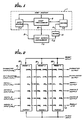
- the environment in which the present invention is used includes a host computer system, indicated by reference numeral 1.
- the host system 1 includes a data source 2, a host processor 3, and a result memory 4, and may have any appropriate detailed architecture.
- the data source 2 is a high-speed magnetic disk storage system
- the host processor 3 is a conventional general-purpose processor
- the memory 4 is a conventional random access memory.
- the fast search processor of the invention receives data from the data source 2 over line 8, and transmits results over line 9 to an output buffer 10, and from there to the result memory 4, over a low-speed line 11.
- the search processor 5 is controlled in an initialization mode, in a search mode, and in a diagnostic mode, by signals received over line 12 from the host processor 3.
- initial values are loaded into the search processor 5 over line 12.
- the processor searches a data stream provided at high speed over line 8, and transmits match results at the same high speed over line 9 to the output buffer 10.
- a design goal of the search processor 5 is to be able to search the data stream at a speed comparable to the access rate of the data source 2. Large data bases can then be searched serially in a reasonable time, without the use of complex and costly indexing schemes.
- the search processor of the preferred embodiment of the invention comprises a multiplicity of identical cells, three of which are shown at 20-22 in FIG. 2.
- the structure of each cell will shortly be explained with reference to FIG. 3, but initially one need only understand that each cell contains a character of a pattern to be searched for, and has a character line (CHAR), an initialization line (INIT), and four match lines (M1-M4), each with an input and output. These lines are connected together serially from cell to cell. Characters in the data stream on line 8 are input to the character line of the first cell 20, and then, on subsequent clock cycles, are shifted through the remaining cells 21 and 22.
- CHAR character line
- IIT initialization line
- M1-M4 match lines
- the first match line M1 is the line on which match results are principally propagated from cell to cell.
- the fourth match line M4 is used to carry a final match result, and the M4 output from the last cell 22 is the result line 9 in FIG. 1.
- the value on the match line M1 indicates a match by the presence of a non-zero value. A zero on the match line represents a non-match. Rather than carrying a simple binary match or non-match value, the match line can be employed in a more general sense to carry a tolerance value indicative of the degree of match.
- this value is initialized to some positive integer, such as "3", whose value is the number of characters of the stored pattern which, if different from the corresponding characters of a character sequence in the data stream, will cause the processor to declare that the character sequence does not match the pattern. If this tolerance value emerges on the result line 9 without change, there is a perfect match. A one-character error, (i.e., discrepancy) between the data stream and the stored pattern would result in a "2" value at the output line 9, and so forth. An “0" value at the output line 9 would indicate "no match” because of a 3-or-more-character error between the data stream and the stored pattern.
- some positive integer such as "3”
- Operation of the cells is in accordance with a relatively straightforward logical sequence, which is identical from cell to cell.
- the character currently in the cell is compared to a pattern character previously stored in the cell.
- the letters C-A-T are assumed to be the pattern characters stored in cells 20-22, respectively. If the characters CAT were to appear in the input data stream, the incoming C would match with the pattern C in the first cell 20. As the character C passes to the second cell 21, it is followed, on match line M1, by a tolerance value indicative of a match in the first cell. More precisely, the indication of a match propagates to the second cell concurrent with the next data character following the matching one.
- the incoming A character is introduced to the second cell 21 and a match is found with the pattern character A in that cell.
- the architecture of the individual cells is such that the tolerance value emerging on match line M1 from the first cell 20 will be passed through the second cell 21 if a match is found in that cell also.
- the tolerance value on match line M1 emerges from the third cell.
- the third cell is the last one in the pattern and, as will be explained, contains a "last" flag that has the effect of transferring the tolerance value from match line M1 to match line M4, from which it emerges on result line 9 to indicate a perfect match. How this comparison function is performed will become apparent from the following description of alternate structural embodiments of a single cell.
- the simplest form of the cell structure includes only a single match line M1, as shown in FIG. 3a.
- the match line is employed to carry a tolerance value of two or more, to represent a degree of mismatch to be tolerated.
- An initial tolerance value is decremented at each cell position in which a mismatch is detected, and emerges from the search processor to provide an indication of the degree of match between the search pattern and a string of characters in the data stream being searched.
- each of the logic elements 80' and 83' is a priority multiplexer, having multiple inputs, designated by numbers in parentheses, and a single output. The operation of each logic element is that the output is chosen from the input whose associated input logic condition is true.
- the logic conditions are set forth in abbreviated form in the logic boxes. If more than one input logic condition is true at the same time, the uppermost input, i.e. the one with the lowest input line number, is chosen as the output. The operation of these logic elements will shortly become clear.
- the cell includes a tolerance register 217', a pattern register 218', a mask register 219', a character register 214', and a comparator 220'.
- the single match line includes an input logic element 80', an M1 match register 87', a second logic element 83', a decrementing circuit 92', and a delay register 91'.
- the input logic element 80' has only two inputs: one from the tolerance register, if the register contains a non-zero value, and the M1 input line M1 i .
- the match register 87' is loaded with the M1 i value only if the tolerance register contains a zero value.
- Logic element 83' operates to decrement the tolerance value if there is no match between the pattern and character registers.
- the delay register 91' is necessary for timing purposes, as will become clear from the following simple search example. Initialization of the alternative cell structure is performed in a manner to be subsequently described in this specification.
- the output of the tolerance register 217' and the comparator 220' are shown as connected to logic elements 80' and 83', respectively, by broken lines. This is because these outputs connect to logic circuitry internal to logic elements 80' and 83' but not shown in FIG. 3a, which implement the logical expressions within the elements. In other words, the contents of the tolerance register and the output of the comparator are transmitted to the logic elements 80' and 83' and are used to control selection of inputs to those elements.
- the simple search can be made with the use of only the single match line M1 of FIG. 3a.
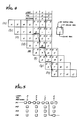
- the mechanics of the search can best be explained in terms of a specific example, shown in FIG. 4.
- Three consecutive cells, indicated as c1, c2 and c3, are initialized with a pattern to be searched for in the incoming data stream.
- the search pattern is the word CAT.
- the pattern registers 218 of the cells contain the letters C, A and T, respectively.
- the length registers 215, the flags 216 and the mask register 219 are not used in the example.
- the tolerance register for the first cell (the c1 cell) is loaded with a desired match tolerance. In the example, this is assumed to be a "1", meaning that a perfect match is desired.
- the tolerance registers of the other cells are set to zero. It will be noted that the tolerance register value will be introduced into the M1 match line, through input (1) of logic element 80', only if the value is non-zero. Accordingly, a tolerance value of "1" will be introduced into the M1 register of the first cell each time a new character is locked into the cell.
- the mask flag has a certain bit set to force a match regardless of whether upper or lower case characters appear in the date. This is indicated by the letter U.
- the key to the matching process is in the role played by the L1 f logic element 83' and the delay register 91'. If there is no match between the character register 214 and the pattern register 218', input (1) is chosen in this logic element, and the tolerance value is decremented to zero in the decrementing circuit 92'. (The decrementing circuit 92' is designed not to decrement the tolerance value below zero). Thus, a non-match in any cell will result in zeroing of the tolerance value in the M1 match line. When a match is found, however, input (2) is selected in the L1 f logic element 83', and the tolerance value is not decremented.
- a match will be found and a tolerance value of "1" will be passed to the delay register 91'.
- the purpose of the delay register 91' is to synchronize the propagation rate of the tolerance value on the M1 match line with that of the data on the character line. For a search pattern of n characters, it will take 2n clock cycles for an n-character sequence within the data stream to pass completely across the search pattern. Therefore, to provide a match result out of the processor when the last data stream character is emerging requires that the M1 match line values progress along the line at half the character clocking rate. The delay register at each cell position takes care of this timing difference.
- the letters CATX are shown as approaching the search pattern.
- the two numerals in each cell represent the tolerance values at the M1 register and the delay register, respectively. These are initially all zero.
- the letter C has advanced to the first cell c1 and a "1" has been introduced into the M1 register.
- the letter C has advanced to the second cell c2 and the letter A as in the first cell c1. Since there was a match in the previous line in the first cell c1, a "1" tolerance value will advance to the delay register in this cell.
- the "1" form the delay register of the first cell is shifted into the M1 register of the second cell c2, where the data character A is aligned with the A of the search pattern.
- the "1" is advanced to the delay register of the second cell c2, since there was previously a match in that cell.
- the "1" is propagated to the M1 register of the third cell c3, where the T characters now match.
- the "1" moves to the delay register of the third cell c3, because of the previous match in that cell.
- multiple match lines are employed to provide the search processor with extended capabilitiesities.
- Second and third search lines are used principally as registers for the temporary storage of match results.
- a number of manipulative functions are needed for the match lines, to enable splitting of a line, exchanging positions of lines, combining lines, and so forth.
- Each cell as shown in FIG. 3, includes seven logic blocks indicated by numerals 80-86, the function of which will be explained as the description proceeds, four match registers 87-90, a delay register 91, and two decrementing circuits 92 and 93.
- each of the logic elements 80-86 is a priority multiplexer having multiple inputs, designated by numbers in parentheses, and a single output. The convention for each logic element is that the output is chosen from the input whose associated input logic condition is true.
- the logic conditions are set forth in abbreviated form in the logic boxes and are further elaborated on in Part B of this description. If more than one input logic condition is true at the same time, the uppermost input, i.e. the one with the lowest input line number, is chosen as the output. The operation of these logic elements will shortly become clear.
- the first match input line M1 i is connected to input (3) of logic element 80, which is also designated L1 i .
- the output of this element passes to the M1 match register 87, from which two possible inputs to logic element 83 are derived.
- Input (1) to logic element 83 is derived by decrementing the M1 register value, in circuit 92, and input (2) is derived directly from the M1 register 87.
- the output of logic element 83 also designated L1 f , passes through the delay register 91 and thence to logic element 85 (L1 o ) as input (4).
- the output of logic element 85 is the first match line output M1 o .
- Alternate paths for the first match line are a feedback path from the output of logic element 83 to input (4) of the logic element L1 i 80, and a path that bypasses the delay 91, extending from the output of logic element 83 to input (3) of logic element L1 o 85.
- the input for the second match line M2 i is connected to inputs (1) and (3) of logic element 81, and as input (2) of logic element 80.
- the output of logic element 81 also designated L2 i , is connected to the M2 match register 88, and thence to input (3) of logic element 84 (directly) and to input (2) of the same element (through decrementing circuit 93).
- the output of logic element 84 also known as L2 o , is the second match line output signal M2 o , which is also fed back to input (4) of the input logic element L2 i 81.
- Input (2) of element L2 i is a forced zero value
- input (1) of logic element L2 o 84 is derived from a value M1 a output from the M1 match register 87.
- FIG. 3b shows the L2 i logic element 81 in more detail.
- the logic element includes a priority encoder 250 and a multiplexer 252.
- the encoder 250 has four inputs, on lines 254-257, which derive their binary inputs from the logical expressions shown in the respective blocks 258-261. When an expression in one of the blocks is true, a "1" input signal is generated on the corresponding input line. If only one of the inputs is a "1," its position is converted by the encoder 250 to an address signal output on lines 266 to the multiplexer 252. If more than one input is a "1,” the priority encoder 250 selects the input line nearest the top of the block, i.e., the line with lowest reference numeral.
- the multiplexer 252 operates in a conventional manner and converts the address on lines 266 to a 1-in-4 internal selection signal, which is used to select one of four input lines 270-273 for output from the multiplexer./
- the other logic elements in FIG. 3 operate in substantiallly the same way.
- the third match line input M3 i is connected to input (2) of logic element 82, also known as L3 i , input (1) being derived from the M1 i signal.
- the output of logic element M3 i is connected to the M3 match register 89, and thence to the output line M3 o .
- the fourth match line input M4 i is connected as the only input to the M4 match register 90, the output of which is connected as input (2) to the logic element 86, also known as L4 o .
- Input (1) to the logic element L4 o is derived from the first match line output M1 o , and the output is the fourth match line output M4 o .
- the cell structure also includes first and second initialization registers 210 and 211.
- An input initialization line INIT i is coupled to the first initialization register 210, the output of which is coupled to the second register 211, from which an output initialization line INIT o is derived.
- An initialization state accumulator 212 is connected to the line between the registers 210 and 211.
- the character input line provides the input to a character register 214.
- a number of other storage registers are shown as connected to the character line, since their values are initialized through the character line. These are the length register 215, the flag register 216, the tolerance register 217, the pattern register 218 and the mask register 219.
- a comparator 220 receives data from the pattern register 218, the character line and the mask register 219. Basically, the comparator 220 compares the data in the character register 214 with the data in the pattern register 218, in conjunction with a mask stored in the mask register 219.
- the only element of the cell yet to be discussed is the counter logic 222. This operates in conjunction with the length register 215 and certain flags in the flag register 216, to control an internal counter used in searching functions.
- FIG. 5 is a match line diagram showing in diagrammatic form how tolerance values are propagated through the interconnected cells. As shown, the tolerance value propagates along the M1 match line until cell c3 is reached. Then the presence of the last flag causes transfer of the tolerance value to the M4 match line.
- FIG. 5 is a match line diagram showing in diagrammatic form how tolerance values are propagated through the interconnected cells. As shown, the tolerance value propagates along the M1 match line until cell c3 is reached. Then the presence of the last flag causes transfer of the tolerance value to the M4 match line.
- the bracket flag effects a splitting or branching of the M1 match line.
- a dedicated cell is needed to perform this function. In other words, no pattern character can be stored in a cell with the bracket flag set. Its effect is to transfer the output of the M1 match register (the M1 a output) to the M2 output line of M2 o of the same cell. On the M2 match line, any value loaded into the M2 register from the M2 i input lines will be ignored when the bracket flag is set.
- FIG. 3 shows the M1 a output as providing input (1) to the L2 o logic element 84.
- the pass flag is set in a cell in which there is a need to bypass the delay register 91 in the M1 match line. Normally, it is desired that the tolerance value in the M1 match line should propagate from cell to cell at half the rate of character propagation. However, there are exceptions that require the delay to be bypassed in some cells.
- the tolerance register 217 is not a flag; it is another register separate from the flag resistor. It is initialized with a positive integer indicating the maximum mismatch that will be tolerated in a pattern search.
- the tolerance value is typically set only for the first character of a pattern of interest.
- the tolerance register value if non-zero, is loaded into the M1 match register 87, as indicated by input (1) of L1 i logic element 80. If the tolerance register contains zero, as will be the case for most cells of the pattern, the input for the M1 match register is usually derived from the M1 input match line M1 i .
- the last flag is set in the last character of a pattern to be searched for.
- the values in the M1 delay register 91 and the M4 match register 90 are compared, and the larger one is placed on the M4 output line M4 o .
- the L4 o logic element 86 has its first input (1) derived from M1 o if the last flag is set and M1 o >M4 a , M4 a being the output from the M4 ma register 90.
- the function of the last flag is also used in logical OR operations.
- the basic OR search has as its goal the location of two or more alternative patterns in the data stream being searched. For example, one may wish to locate the occurrences of the words CAT or DOG or MAN. A simple search using only one match line would require three passes through the entire data stream to perform the OR function.
- the OR search is made using match line M4 in conjunction with the tolerance register 217 and the last flag.
- the first pattern, CAT appears in the cells in a normal manner.
- the C character sets the tolerance register to a desired value, and the last character, T, has the last flag set.
- the result of the CAT match if any, is transferred to the M4 match line.
- a match result emerges from the last cell of a pattern with the character following the last matching character of the data stream being searched.
- the letter following CAT is assumed to be X, for example, then the match result will emerge from the T cell as the X character emerges from the character register of the T cell. Since the M4 match line has only one register, the match value will propagate along the M4 match line in synchronism with the X character of the data stream.
- the last-flag logic selects the larger match value for the output on the M4 line. This is shown in the input logic for input (1) of logic element 86 (L4 o ).
- Such a conflict between results on the M4 line would occur only when two ORed search patterns were of equal length and were almost identical, within the tolerance selected for the search. For example, a search for DOG or LOG with a tolerance of two or more would result in both OR paths detecting a match when DOG appeared in the data stream. DOG would match exactly and LOG would match with a lower tolerance but both match results would compete for the M4 o line and the larger tolerance would be selected.
- the addition of the third search pattern, MAN is treated in identical fashion.
- the M character of the pattern resets the tolerance value for the search, and the N character of the pattern has its last flag set, to transfer any match result to the M4 line.
- the OR flag affects three match lines: M1, M2, and M3.
- the M2 input value, on line M2 i is loaded into the M1 match register 87
- the M1 input value, on line M1 i is loaded into the M3 match register 89.
- the OR flag When used subsequent to a bracket flag, the OR flag permits retrieval of a previous result saved in the M2 match line, and at the same time saves the current M1 match result in the M3 match line.
- the practical importance of the OR flag will become apparent from examples to be described after the choose flag has been introduced.
- the choose flag affects the output of the first match line, on line M1 o .
- the values in the M3 match register 88 and the M1 delay register 91 are compared, and the larger value is output on the M1 o output line. This choice is made at input (2) of the L1 o logic element 85. If the pass flag is set as well as the OR flag, the M3 delay register 91 is bypassed and the comparison is made between M3 and the output from the M1 match register 87, on line M1 f .
- the common-prefix OR search is an OR search in which each of the alternative patterns has a common prefix pattern. For example, suppose one wished to locate the occurrence of OLD CAT or OLD DOG or OLD MAN. While this may seem trivial, for longer search patterns it would be desirable not to have to repeat the prefix several times in the search pattern.
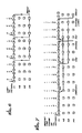
- the common-prefix search solves this problem by means of the bracket, OR and choose flags, as shown in FIG. 7.
- the common-prefix pattern, OLD appears first in the search pattern, and the result of the prefix search appears on the M1 match line in the same manner as in a simple search.
- the next cell after the prefix is a bracket cell, having both the bracket flag and the pass flag set. As will be recalled, this splits the M1 tolerance value and places it on the M2 line as well as on the M1 line of subsequent cells.
- the first suffix pattern, CAT is searched for, so that the last cell (T) in this segment will produce a result indicative of the OLD CAT search.
- the first cell of the next segment of the search pattern, the D cell has the OR flag set, and this results in saving the OLD CAT result in the M3 match line and retrieving the prefix search result (OLD) from the M2 match line.
- the third segment of the search effects a search for OLD DOG, while propagating the OLD search result through the M2 match line and propagating the OLD CAT search result through the M3 search line.
- the last letter of the third segment, the G cell has its choose flag set. In the general case, this effects a choice of the larger of the M3 value and the M1 value. In most practical situations, however, there will be no conflict between the M3 and M1 values. If a match had been found for OLD CAT, by the time a subsequent match had been found for OLD DOG the OLD CAT match value would have been propagated out of the processor.
- the choose function either takes the OLD CAT match value from M3 or the OLD DOG match value already on M1 and outputs it on the M1 o line.
- the fourth segment of the search pattern functions in a similar way to the third.
- the first cell, the M cell has its OR Flag set, to save the M1 match value in M3 again, and to retrieve the prefix match value from M2.
- matching proceeds for the OLD MAN pattern, and in the N cell the choose flag again effects a choice between the OLD MAN match value on the M1 line and a possible OLD CAT or OLD DOG match on line M3. Again there is little possibility of two simultaneous matches of the alternative patterns, unless the patterns are of equal length and nearly similar content.
- the search pattern might be: MARCH XX, 1972, where XX denote don't-care characters.
- the search could be implemented by setting all bits of the mask register in the two cells of the search pattern corresponding to the day of the month. Bit positions of the character register corresponding to the set positions of the mask register are ignored in the comparison process. If all bits of the mask register are set, a match in that cell is assured, regardless of the content of the character register.
- variable-length don't care function is effected by means of a special cell with the mask register bits all set, operating in conjunction with the counter and length register 215 in the same cell.
- the "don't care” cell is placed in the search pattern at the position at which a variable-length don't care string is permitted.
- the search pattern will be MARCH*1972, where the asterisk represents the "don't care” cell.
- the * cell has its length counter initialized to a value corresponding to the don't- care count of ten.
- the action of the * cell is, therefore, to transmit this recirculated match value on the M1 o line up to ten times. If the next following character does not match the "1" in the second part of the pattern (1972), the match value will be decremented in the usual way and a match result may not emerge from the end of the pattern. If the string 1972 follows the string MARCH within the designated ten characters, then one of ten match values output by the * cell will be propagated all the way through the search pattern, indicating a match within the don't-care range that was specified.
- variable-length don't-care search is obtained by setting the pass flag in the don't-care cell. This permits a zero-length don't-care between the two search patterns. That is to say, the number of don't-care characters may be from zero to a selected count, rather than from one to the selected count.
- a related search condition is the "variable-length care" condition, in which a specific character may occur repeatedly in a character string. For example, one may wish to find the words FAT and CAT separated by up to five spaces.
- the search pattern is FAT CAT, with the fourth cell containing a space character and not having its pass flag set.
- the length register in this cell is initialized to a value of five, and this value is loaded into the counter when a match is found in the first part of the pattern (FAT).
- the match value from the first part of the pattern is recirculated five times while the counter is being decremented, so long as spaces appear between the words FAT and CAT. If the second part of the pattern (CAT) appears within five spaces of the first part, one of these circulated match values will be propagated completely through the pattern if the second part of the pattern is detected.
- the negate flag has the effect of: (1) repeatedly outputting the value in the M2 match register on the M1 output line M1 o , and (2) if the incoming value on the M2 input line M2 i is greater than the previous value M2 o loading the incoming M2 i value in the M2 match register. If the incoming M2 i value is not greater than the previous value, M2 will either be retained as it was or will be zeroed, depending on whether M1 i is zero or non-zero. The implications of these alternative actions will become clear from the example depicted in FIG. 8.
- the negate flag is used to create patterns that will be considered to match if certain strings are not present in the incoming data stream. For example, if one wishes to find the words FAT CAT but without the word BLACK between them. In other words FAT BLACK CAT would not be a match, but FAT WHITE CAT would be.
- the search pattern is FAT[BLACKnCAT, where [ is a cell with its bracket flag set and n is a cell with its negate flag set.
- the match value is passed to the M2 match line by action of the bracket flag, and is also retained in the M1 match line.
- the tolerance value is reset in the first cell of second segment (BLACK). Therefore, at the end of the second pattern segment (BLACK), the M1 match line will carry an indication of whether or not the pattern BLACK was found in the data stream.
- the M2 i incoming match line will indicate whether a match for the first pattern segment (FAT) was found.
- M2 i is greater than its previous value, a match is indicated and M2 match register is loaded. This loading step is through input (1) of the L2 i logic element 81.
- the negate cell continues to recirculate the value in its M2 match register, and to transfer this value back to the M1 match line. Transfer back to the M1 match line is made through input (1) of the L1 o logic unit 85. Recirculation of the M2 value is made through input (4) of the L2 i logic element 81. If a match is then found for the third segment (CAT), a non-zero match value will emerge from the processor in the usual manner.
- CAT third segment
- a match is found for BLACK, a non-zero match value is presented to the negate cell in its M1 i line, and this results in a zero value being placed on the M2 match register. This operation takes place as a result of the zero connected to input (2) of the L2 i logic element 81. The zero match value is also transferred to the M1 match line in the negate cell, and no match can then be found for the entire pattern, regardless of whether or not the last segment matches.
- the negate logic functions principally as a result of the configuration of the L2 i logic element 81.
- Input (1) is selected when the M2 register is first loaded in the negate cell
- input (2) is selected when a match of the unwanted pattern segment is located
- input (4) is selected when the M2 value is recirculated. It will be understood that the last cell in any search pattern should have its last flag set, to transfer the final result of the search to the M4 result line.
- the right flag works in conjunction with the length counter and performs a function similar in some respects to that of the negate flag. If the incoming value M2 i on the M2 match line is non- zero, it is loaded into the M1 match register. This is effected through input (2) of the L2 i logic element 80. If the value in the M1 match register is zero, or if the length counter has reached zero, the value loaded into the M2 match register is decremented by one and is output on the M1 o output line. Otherwise, i.e. if M1 is not zero and the counter is not zero, then the value loaded into the M2 match register is output directly onto the M1 o output line. The value output from M2 to the M1 o output line is also recirculated to the M2 match register, through input (4) of the L2 i logic element 81.
- the incoming value on the M2 i line is loaded into the M2 match register only if it is greater than the previous M2 value (M2 o ). This is accomplished by input (1) of the L2 i logic element 81, and is similar in operation to the negate flag.
- the right flag provides a method for extending the concept of a variable-length care string in the search pattern, to allow a variable mix of several different specific characters, as the example shown in FIG. 9 illustrates.
- the search pattern includes the name JEAN-PAUL. It is concluded that the hyphen may be replaced by a space, or a tab character, or some combination of these. Accordingly, the ideal search pattern would find a match if the data stream included any combination, up to a specified count, of several specified characters; for example, any five characters including hyphens, spaces and tabs, but no other characters.
- the right flag permits this function to be performed.
- the search pattern stored is JEAN[ -t]PAUL, where [ is a cell with the bracket flag set, t is a tab character, and ] is a cell with the right flag set.
- JEAN The first segment of the pattern (JEAN) generates a match value in the M1 match line in the normal manner. Then the bracket cell copies this value in the M2 match line.
- the tolerance register is set to one, so the search for the characters following the bracket requires an exact match of one of the selected characters between the bracket and the cell with its right flag set.
- the cell containing the hyphen has both the OR flag and the choose flag set.
- the OR flag results in the M1 i value being transferred to M3 and the M2 i value being copied to M1.
- the choose flag in the same cell chooses the larger of the M3 and M1 values.
- the search pattern is quite similar to the one used in a common-prefix logical OR search. A non-zero output will be generated on the M1 match line if any one of the three characters is detected.
- the next cell, with the right flag set, may be thought of as a "closing bracket.” If the input on the M2 i line is non-zero, indicating a prefix match, the counter is loaded with the length register value. If the M1 i line also indicates a match, meaning that one of the three designated characters followed the prefix, then the M2 match value is recirculated and is also transferred to the M1 match line for use in matching the suffix pattern segment. If the M1 i indicates no match, i.e. that a character other than one of the specified three followed the prefix, then the M2 value is decremented by one, recirculated, and also transferred to the M1 match line.
- the cell with the right flag will continue to generate a match indicator. If a different character is interposed in the stream, or if the count is decremented to zero, the tolerance value will be decremented and the cell output may indicate a non-match.
- Counter loading is initiated by the first load condition in the counter logic.
- the transfer of non-zero M2 tolerance value back to the M1 match line in a right-flag cell, is effected by input (2) of the L1 i logic element, which is the selected input when M2 i is non-zero.
- the M1 i line should normally return to zero, and the counter will be decremented on each cycle.
- the M1 register will then derive its input from the M1 i line rather than the M2 i , as indicated by input (3) of the L1 i logic element.
- the M2 match output, on line M2 o is always transferred to the M1 o line, through input (1) of the L1 o logic element 85.
- the value of the output transferred is determined by the condition of the M1 match register 87 (M1 a ) and by the condition of the counter. If M1 a or the counter is zero, this indicates that either there is no current match within the brackets, or the match result in M2 has been output to M1 more than a selected number of times. In either case, the M2 match value is decremented prior to its next output on the M1 o line. If M1 a is non-zero, meaning that a matching character was found between the brackets, and the counter is non-zero, then the M2 match value is recirculated without change in the M2 line.
- the recirculation of M2 values in a right-flag cell is effected through input (4) of the L2 i logic element 81. Decrementing the M2 value is accomplished by the decrementing circuit 93, which is selected by input (2) of the L2 o logic element 84.
- Initialization of the search cells is controlled by the initialization logic, which consists of a counter 300 and a decoder 302, as shown in FIG. 10.
- the counter 300 is of the synchronous binary type, with three bits of output, on lines 304, a separate count enable control on line 306, and a means for restarting the count from zero, on line 308.
- the binary counter value provides the input to the decoder 302 over lines 304.
- the first five outputs of the decoder which are selected when the counter has a value between zero and four, form the clock lines for the five registers to be programmed during initialization.
- the sixth output is left unused so that external circuitry may be initialized on one of the initialization passes without affecting the cells.
- the seventh output is used to put the cell into search mode and to disable the counter, such that the seventh output remains enabled until the next reset cycle.
- the initialization counter 300 clocks on the falling edge of a clock signal CLKI applied to the counter, but only when two conditions are met.
- the first condition is that the count has not yet reached seven, as discussed.
- the second condition is that, on the previous rising edge of CLKI, the INITI line was asserted.
- This is simply the output of a D flip-flop 210 in the INITI-INITO connection inside the cell.
- This flip-flop output is counted as one input of an AND gate 310, the other input being derived from the seventh output of the decoder 302.
- the output of the AND gate 310 is the enable line 306 of the counter 300.
- the output of the character register 214 provides the data for loading into each of the registers during initialization.
- the output of the character register becomes valid after a rising edge of CLKI, and the initialization counter counts after a falling edge of CLKI (if INITI was previously asserted).
- the initialization counter 300 counts, the output selected by the decoder is deselected, and this transition is used to store the output of the character register in one of the five registers to be initialized.
- the character input lines are used to provide the data that programs the cell during initialization.
- the initialization cycle repeats with a reset of a cell or group of cells.
- a reset involves the momentary assertion of the RESETI line, causing the cell to assume a known initial state.
- the important feature of this state is the initialization counter restarting its count from zero.
- Groups of cells are formed by connecting the outputs of one cell to the inputs of the next, with the CLKI and RESETI signals shared among all cells in a group.
- the initialization scheme is designed so that any cell in the group can be programmed by manipulation of inputs to only the first cell, therefore requiring no extra lines to control and use a group of cells independently of the number of cells in the group.
- This feature of the initialization scheme depends on the second D-type flip-flop 211 in the INITI to INITO connection in a cell.
- the presence of a second flip-flop causes the data that was present at the INITI line of the cell to appear on the INITO line after the second rising edge of CLKI.
- the data at the character input (CI) lines appears on the character output (CO) lines after the first rising edge of CLKI.
- the INITI signal from one cell reaches the INITI of the next cell along with the second character given to the CI of the first cell.
- the INITI signal would reach the third cell along with the third character given to the CI of the first cell.
- the initialization procedure for n cells can be outlined as follows:
- step 4 pulsing the clock signal causes the decoder 302 to advance from its first to its second output, thereby clocking data from the character register into the first register (the pattern register). Since the INITI signal is then deasserted (step 5), subsequent clock pulses do not affect the first cell .However, the INITI signal pulse is propagated from cell to cell, to effect initialization of the first register in each cell, as defined by steps 6, 7 and 8. to initialize the second register in each cell, the INITI signal is asserted again (step 2), and subsequent clock signals effect initialization of the second register.
- this initialization scheme is flex strictlyible in that it will allow the programming of any number of registers as exist in the cell without adding any additional lines for control or data.
- the only added complexity may be to increase the number of bits provided by the initialization counter 300 and decoder 302, both of which are internal to a cell.
- the cells are operated in a search mode.
- the INITI line is asserted a final time, and the first character of a stream of characters to be searched against the data stored in the cells is presented to the CI lines of the first cell in the group.
- the match input lines to the first cell are held at logical zero.
- the CLKI line is pulsed to clock the character into the cell's character register.
- the match logic compares the character with the pattern and produces a result on the match output lines.
- the second character is presented on the CI lines of the first cell, and the cycle repeats, with the first character and match output being loaded in the second cell on the same rising edge of CLKI which loads the second character. This cycle is repeated for every character to be searched.
- the information is carried along the match output lines and is detected as a match when it appears at the last cell in the group, as described in the foregoing descriptive sections.
- the present invention represents a significant advance in the field of special search processors.
- the use of tolerance values to represent a degree of matching provides a useful improvement over a simple binary match result.
- the use of multiple match lines for storing and manipulating match results provides a variety of search possibilities, all of which are performed in a concurrent or systolic manner.
Landscapes
- Engineering & Computer Science (AREA)
- Databases & Information Systems (AREA)
- Theoretical Computer Science (AREA)
- Computational Linguistics (AREA)
- Data Mining & Analysis (AREA)
- Physics & Mathematics (AREA)
- General Engineering & Computer Science (AREA)
- General Physics & Mathematics (AREA)
- Information Retrieval, Db Structures And Fs Structures Therefor (AREA)
Priority Applications (3)
| Application Number | Priority Date | Filing Date | Title |
|---|---|---|---|
| EP85307919A EP0222940B1 (de) | 1985-10-31 | 1985-10-31 | Schneller Recherchenprozessor und Verfahren für seine Benutzung |
| DE8585307919T DE3585411D1 (de) | 1985-10-31 | 1985-10-31 | Schneller recherchenprozessor und verfahren fuer seine benutzung. |
| US06/946,655 US4760523A (en) | 1984-06-29 | 1986-12-24 | Fast search processor |
Applications Claiming Priority (1)
| Application Number | Priority Date | Filing Date | Title |
|---|---|---|---|
| EP85307919A EP0222940B1 (de) | 1985-10-31 | 1985-10-31 | Schneller Recherchenprozessor und Verfahren für seine Benutzung |
Publications (2)
| Publication Number | Publication Date |
|---|---|
| EP0222940A1 true EP0222940A1 (de) | 1987-05-27 |
| EP0222940B1 EP0222940B1 (de) | 1992-02-19 |
Family
ID=8194421
Family Applications (1)
| Application Number | Title | Priority Date | Filing Date |
|---|---|---|---|
| EP85307919A Expired - Lifetime EP0222940B1 (de) | 1984-06-29 | 1985-10-31 | Schneller Recherchenprozessor und Verfahren für seine Benutzung |
Country Status (2)
| Country | Link |
|---|---|
| EP (1) | EP0222940B1 (de) |
| DE (1) | DE3585411D1 (de) |
Cited By (2)
| Publication number | Priority date | Publication date | Assignee | Title |
|---|---|---|---|---|
| EP0233401A2 (de) | 1985-12-10 | 1987-08-26 | Trw Inc. | Schneller Suchprozessor |
| WO2000029981A3 (en) * | 1998-11-13 | 2000-08-10 | Fast Search & Transfer Asa | A processing circuit and a search processor circuit |
Citations (3)
| Publication number | Priority date | Publication date | Assignee | Title |
|---|---|---|---|---|
| EP0054588A1 (de) * | 1980-12-19 | 1982-06-30 | International Business Machines Corporation | Interaktives Datenwiederauffindungsgerät |
| EP0084626A1 (de) * | 1982-01-21 | 1983-08-03 | General Electric Company | Hochgeschwindigkeits-Suchsystem |
| GB2156115A (en) * | 1984-03-12 | 1985-10-02 | Secr Defence | Regular expression recognition apparatus |
-
1985
- 1985-10-31 DE DE8585307919T patent/DE3585411D1/de not_active Expired - Lifetime
- 1985-10-31 EP EP85307919A patent/EP0222940B1/de not_active Expired - Lifetime
Patent Citations (3)
| Publication number | Priority date | Publication date | Assignee | Title |
|---|---|---|---|---|
| EP0054588A1 (de) * | 1980-12-19 | 1982-06-30 | International Business Machines Corporation | Interaktives Datenwiederauffindungsgerät |
| EP0084626A1 (de) * | 1982-01-21 | 1983-08-03 | General Electric Company | Hochgeschwindigkeits-Suchsystem |
| GB2156115A (en) * | 1984-03-12 | 1985-10-02 | Secr Defence | Regular expression recognition apparatus |
Non-Patent Citations (1)
| Title |
|---|
| COMPUTER, vol. 13, no. 1, January 1980, pages 26-40, IEEE, Long Beach, CA, US; M.J. FOSTER et al.: "The design of special-purpose VLSI chips" * |
Cited By (5)
| Publication number | Priority date | Publication date | Assignee | Title |
|---|---|---|---|---|
| EP0233401A2 (de) | 1985-12-10 | 1987-08-26 | Trw Inc. | Schneller Suchprozessor |
| EP0233401A3 (de) * | 1985-12-10 | 1991-10-30 | Trw Inc. | Schneller Suchprozessor |
| WO2000029981A3 (en) * | 1998-11-13 | 2000-08-10 | Fast Search & Transfer Asa | A processing circuit and a search processor circuit |
| US6587852B1 (en) | 1998-11-13 | 2003-07-01 | Fast Search & Transfer Asa | Processing circuit and a search processor circuit |
| RU2216772C2 (ru) * | 1998-11-13 | 2003-11-20 | Фаст Серч Энд Трансфер Аса | Схема обработки и схема процессора поиска |
Also Published As
| Publication number | Publication date |
|---|---|
| EP0222940B1 (de) | 1992-02-19 |
| DE3585411D1 (de) | 1992-03-26 |
Similar Documents
| Publication | Publication Date | Title |
|---|---|---|
| US4760523A (en) | Fast search processor | |
| US5051947A (en) | High-speed single-pass textual search processor for locating exact and inexact matches of a search pattern in a textual stream | |
| US4567572A (en) | Fast parallel sorting processor | |
| US3636519A (en) | Information processing apparatus | |
| US5452451A (en) | System for plural-string search with a parallel collation of a first partition of each string followed by finite automata matching of second partitions | |
| US4221003A (en) | Bubble domain relational data base system | |
| US4520456A (en) | Dual reciprocating pipelined sorter | |
| US4283771A (en) | On-chip bubble domain relational data base system | |
| Krylov et al. | Globally asynchronous, locally synchronous clocking and shared interconnect for large-scale SFQ systems | |
| Chang | An on-chip compare/steer bubble sorter | |
| Lindon et al. | An optimal implementation of broadcasting with selective reduction | |
| Yamada et al. | A high-speed string-search engine | |
| US5502832A (en) | Associative memory architecture | |
| EP0222940B1 (de) | Schneller Recherchenprozessor und Verfahren für seine Benutzung | |
| Burkowski | A hardware hashing scheme in the design of a multiterm string comparator | |
| Chung | On the complexity of sorting in magnetic bubble memory systems | |
| JPH03129521A (ja) | 分類加速装置の安定分類 | |
| Lee | ALTEP—A cellular processor for high-speed pattern matching | |
| JPH061476B2 (ja) | 高速検索処理装置 | |
| Lee et al. | Text retrieval machines | |
| Takahashi et al. | Intelligent string search processor to accelerate text information retrieval | |
| JPH0380366A (ja) | ストリングサーチ方法およびそのための装置 | |
| JPH0317780A (ja) | 記号列検索方法および装置 | |
| Hurson et al. | Specialized parallel architectures for textual databases | |
| Parhami | The mixed serial/parallel approach to VLSI search processors |
Legal Events
| Date | Code | Title | Description |
|---|---|---|---|
| PUAI | Public reference made under article 153(3) epc to a published international application that has entered the european phase |
Free format text: ORIGINAL CODE: 0009012 |
|
| AK | Designated contracting states |
Kind code of ref document: A1 Designated state(s): DE FR GB IT SE |
|
| 17P | Request for examination filed |
Effective date: 19871030 |
|
| 17Q | First examination report despatched |
Effective date: 19890905 |
|
| ITF | It: translation for a ep patent filed | ||
| GRAA | (expected) grant |
Free format text: ORIGINAL CODE: 0009210 |
|
| AK | Designated contracting states |
Kind code of ref document: B1 Designated state(s): DE FR GB IT SE |
|
| REF | Corresponds to: |
Ref document number: 3585411 Country of ref document: DE Date of ref document: 19920326 |
|
| ET | Fr: translation filed | ||
| PLBE | No opposition filed within time limit |
Free format text: ORIGINAL CODE: 0009261 |
|
| STAA | Information on the status of an ep patent application or granted ep patent |
Free format text: STATUS: NO OPPOSITION FILED WITHIN TIME LIMIT |
|
| 26N | No opposition filed | ||
| EAL | Se: european patent in force in sweden |
Ref document number: 85307919.2 |
|
| REG | Reference to a national code |
Ref country code: GB Ref legal event code: IF02 |
|
| PGFP | Annual fee paid to national office [announced via postgrant information from national office to epo] |
Ref country code: GB Payment date: 20040915 Year of fee payment: 20 |
|
| PGFP | Annual fee paid to national office [announced via postgrant information from national office to epo] |
Ref country code: FR Payment date: 20041004 Year of fee payment: 20 |
|
| PGFP | Annual fee paid to national office [announced via postgrant information from national office to epo] |
Ref country code: SE Payment date: 20041005 Year of fee payment: 20 |
|
| PGFP | Annual fee paid to national office [announced via postgrant information from national office to epo] |
Ref country code: DE Payment date: 20041029 Year of fee payment: 20 |
|
| PG25 | Lapsed in a contracting state [announced via postgrant information from national office to epo] |
Ref country code: GB Free format text: LAPSE BECAUSE OF EXPIRATION OF PROTECTION Effective date: 20051030 |
|
| PG25 | Lapsed in a contracting state [announced via postgrant information from national office to epo] |
Ref country code: SE Free format text: LAPSE BECAUSE OF NON-PAYMENT OF DUE FEES Effective date: 20051101 |
|
| REG | Reference to a national code |
Ref country code: GB Ref legal event code: PE20 |
|
| EUG | Se: european patent has lapsed |