EP0222941A1 - Mittels Feder blockierte verstellbare Riemenscheibe - Google Patents
Mittels Feder blockierte verstellbare Riemenscheibe Download PDFInfo
- Publication number
- EP0222941A1 EP0222941A1 EP85307994A EP85307994A EP0222941A1 EP 0222941 A1 EP0222941 A1 EP 0222941A1 EP 85307994 A EP85307994 A EP 85307994A EP 85307994 A EP85307994 A EP 85307994A EP 0222941 A1 EP0222941 A1 EP 0222941A1
- Authority
- EP
- European Patent Office
- Prior art keywords
- pulley
- shaft
- spring
- movable
- stop member
- Prior art date
- Legal status (The legal status is an assumption and is not a legal conclusion. Google has not performed a legal analysis and makes no representation as to the accuracy of the status listed.)
- Granted
Links
- 238000004519 manufacturing process Methods 0.000 description 2
- 230000003252 repetitive effect Effects 0.000 description 1
- 238000004804 winding Methods 0.000 description 1
Images


Classifications
-
- F—MECHANICAL ENGINEERING; LIGHTING; HEATING; WEAPONS; BLASTING
- F16—ENGINEERING ELEMENTS AND UNITS; GENERAL MEASURES FOR PRODUCING AND MAINTAINING EFFECTIVE FUNCTIONING OF MACHINES OR INSTALLATIONS; THERMAL INSULATION IN GENERAL
- F16H—GEARING
- F16H55/00—Elements with teeth or friction surfaces for conveying motion; Worms, pulleys or sheaves for gearing mechanisms
- F16H55/32—Friction members
- F16H55/52—Pulleys or friction discs of adjustable construction
- F16H55/56—Pulleys or friction discs of adjustable construction of which the bearing parts are relatively axially adjustable
Definitions
- This invention relates to a variable speed pulley, and more particularly to a spring-locked speed change pulley for use, for example, as a drive device in an automobile, a motorcycle, an agricultural machine, or an industrial machine.
- variable speed pulleys have been disclosed, for example in Japanese Published Utility Model Application No. 35421/1977, Japanese Laid-Open Utility Model Application (Kokai) No. 122847/1984, and Japanese Laid-Open Patent Application (Kokai) No. 79355/1982.
- a pair of V-shaped pulley parts are mounted on a shaft in such a manner that either one or both of the two pulley parts are rotatable around the shaft and are movable along the shaft.
- a stop member is fixedly mounted on the shaft, located adjacent the or each movable pulley part.
- a coil spring is interposed between the or each movable pulley part and the adjacent stop member to absorb the torque which is developed during operation of the pulley.
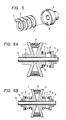
- a coil spring 4 is wound during manufacture in the same direction as it is wound as the pulley rotates. Both ends of the spring are bent and engaged with holes formed in the movable pulley part 3 and a flange of a stop member 5 provided alongside the movable pulley part. Accordingly, when the movable pulley part is rotated repetitively in the forward and reverse directions by the variations in torque,the ends of the spring may be broken.
- variable speed pulleys disclosed by Japanese Laid-Open Patent Application No. 79355/1982 and Japanese Published Utility Model Application No. 122847/1984, as shown in Figures 2 and 3 herein, respectively, the ends of the spring 4 are fitted in tapered grooves in the pulley part 3 and the stop member 5, or abutted against protrusions. Therefore, in these variable speed pulleys, unlike the above-described ones, the ends of the spring will not be broken by repetitive forward and reverse rotation. However, because the spring is only unwound, it cannot transmit torque developed between the stop member 5 and the movable pulley part 3 in both the forward and reverse directions. Hence, those variable speed pulleys also suffer from the disadvantage that they have a very limited range of application.
- An object of the present invention is to provide an improved variable speed pulley which has a wide range of application and, more specifically, to improve the way in which the spring is engaged with the sides of the stop member and the movable pulley part so that the torque which is developed between the stop member and the movable pulley part in the forward and reverse directions can be effectively transmitted.
- a variable-speed pulley comprising two confronting pulley parts mounted on a shaft, at least one of the pulley parts being mounted on the shaft to be movable in an axial direction of the shaft and to be rotatable around the shaft; and, associated with the or each movable pulley part, a respective stop member fixedly mounted on the shaft, and a coil spring interposed between the movable pulley part and the stop member; wherein the or each movable pulley part and the or each stop member has a respective pin protruding from confronting sides thereof; and wherein the or each coil spring has a hole in each of its ends which engages with a respective one of the pins, whereby, in operation, when a belt drives, or is driven by, the pulley, so that the coil spring is rotated in a direction in which it is wound or in the direction opposite thereto, a torque in either direction is withstood.
- the coil spring may be circular in section, but it is also possible to use a coil spring of rectangular section because the ends of the spring where the holes are located can have a large effective spring height.
- a variable speed pulley constructed according to the present invention is shown in Figure 6A.
- the pulley is shown in its normal operating state with a V-belt 9 laid therearound.
- the pulley comprises a fixed pulley part 1 which is mounted on a shaft S and is locked thereto by a screw 2.
- a movable pulley part 3 is mounted on the shaft confronting the stationary pulley part 1. More specifically, the movable pulley part 3 is mounted on the shaft S in such a manner that it is rotatable relative to the shaft, and it is movable in the direction of thrust, i.e. in the axial direction of the shaft.
- An annular groove 3' is formed in the base of a boss protruding from the movable pulley part 3.
- a flanged stop member 5 is mounted on the shaft S and is fixed thereto by a screw 6.
- a coil spring 4 is resiliently interposed between the movable pulley part 3 and the stop member 5 in such a manner that the ends of the spring 4 are held, respectively, in the groove 3' and in an annular recess formed in the stop member 5.
- the movable pulley part 3 is urges in the axial direction, towards the pulley part 1, by the coil spring.
- holes 7 and 7' are formed in the ends of the spring 4.
- a pin 8 protrudes from the bottom of the annular groove 3', and similarly a pin 8' protrudes from the bottom of the annular recess in the stop member 5.
- the pins 8 and 8' are engaged with the holes 7 and 7', respectively, and thereby lock the spring 4 to the pulley part 3 and the stop member 5.
- the holes 7 and 7' are located 180° apart around the longitudinal axis of the spring 4.
- the coil spring 4 shown in Figures 5, 6A and 6B is rectangular in section. However, the spring may alternatively be circular in section, as shown in Figure 4. Of the two types, for given values of spring constant, effective diameter and free length, a spring of rectangular cross section is preferred because of its greater twisting rigidity, i.e. smaller helix angle, and because it can withstand large loads.
- variable speed pulley may be modified so that both of the pulley parts are movable and have respective stop members, and respective coil springs are interposed therebetween. Such an arrangement is shown in Figure 6B.
- variable speed pulley thus constructed will be described.
- variable speed pulley As described above, in the variable speed pulley according to the invention, one of the pulley parts forming the variable speed pulley is movable and rotatable around the shaft, and the coil spring is interposed between the movable pulley part and the stop member by engagement between the holes and the pins. Accordingly, the belt can be positioned in a balanced state due to the resilient force of the spring, and the effective diameter of the variable speed pulley can be readily changed by adjusting the belt tension.
- variable speed pulley can bear a load not only in the coil spring winding direction but also in the coil spring unwinding direction, so that the pulley has a wider range of use than the conventional pulley.
- the spring Since the protruding pins are engaged with the holes in the ends of the coil spring, the spring has no bent parts, and accordingly there is considerably less likelihood of breakage of the spring when the torque is transmitted through the coil spring repetitively in the forward and reverse directions. Hence, the pulley can be effectively employed in a variety of industrial fields, thereby increasing its range of application.
Landscapes
- Engineering & Computer Science (AREA)
- General Engineering & Computer Science (AREA)
- Mechanical Engineering (AREA)
- Transmissions By Endless Flexible Members (AREA)
Priority Applications (1)
| Application Number | Priority Date | Filing Date | Title |
|---|---|---|---|
| DE8585307994T DE3576190D1 (de) | 1985-11-04 | 1985-11-04 | Mittels feder blockierte verstellbare riemenscheibe. |
Applications Claiming Priority (1)
| Application Number | Priority Date | Filing Date | Title |
|---|---|---|---|
| US06/794,877 US4626227A (en) | 1985-11-04 | 1985-11-04 | Spring-locked variable speed pulley |
Publications (2)
| Publication Number | Publication Date |
|---|---|
| EP0222941A1 true EP0222941A1 (de) | 1987-05-27 |
| EP0222941B1 EP0222941B1 (de) | 1990-02-28 |
Family
ID=25163961
Family Applications (1)
| Application Number | Title | Priority Date | Filing Date |
|---|---|---|---|
| EP85307994A Expired - Lifetime EP0222941B1 (de) | 1985-11-04 | 1985-11-04 | Mittels Feder blockierte verstellbare Riemenscheibe |
Country Status (2)
| Country | Link |
|---|---|
| US (1) | US4626227A (de) |
| EP (1) | EP0222941B1 (de) |
Families Citing this family (2)
| Publication number | Priority date | Publication date | Assignee | Title |
|---|---|---|---|---|
| DE10209393A1 (de) * | 2002-03-02 | 2003-09-11 | Rieter Ingolstadt Spinnerei | Regelscheibe für ein Riemengetriebe |
| US20070099734A1 (en) * | 2005-10-28 | 2007-05-03 | Hansen Roy D | Bushingless variable speed separator drive |
Citations (6)
| Publication number | Priority date | Publication date | Assignee | Title |
|---|---|---|---|---|
| US3444749A (en) * | 1966-02-24 | 1969-05-20 | Heinkel Ag Ernst | Variable pitch sheave and helical spring structure |
| DE1550836A1 (de) * | 1966-10-07 | 1969-07-03 | Lerch Dipl Ing Friedrich | Regelscheibe fuer Keilriementriebe |
| DE1525013A1 (de) * | 1965-08-10 | 1969-09-18 | Ambros Geb Altenhoefer Margare | Selbstregelnde,drehmomentabhaengige Antriebs- oder Abtriebsscheibe fuer spannungsregulierenden Antrieb eines fortlaufenden,aufzuwickelnden oder abzuwickelnden Warengutes,Sanftanlauf usw. |
| US3861228A (en) * | 1972-07-24 | 1975-01-21 | Hugh L Adams | Torque controlling sheave |
| GB2018915A (en) * | 1978-04-17 | 1979-10-24 | Borg Warner | Expanding-pulley drive system |
| EP0051497A2 (de) * | 1980-11-05 | 1982-05-12 | Mitsuboshi Belting Ltd. | Verstellbare Riemenscheibe |
Family Cites Families (4)
| Publication number | Priority date | Publication date | Assignee | Title |
|---|---|---|---|---|
| US2892354A (en) * | 1957-12-13 | 1959-06-30 | George H Amonsen | Variable speed pulley |
| US4061047A (en) * | 1976-09-20 | 1977-12-06 | Deere & Company | Pulley half mounting of variable speed pulley |
| US4541821A (en) * | 1982-11-27 | 1985-09-17 | Aisin-Warner Limited | V-belt type stepless transmission |
| JPS59128954U (ja) * | 1983-02-18 | 1984-08-30 | 三ツ星ベルト株式会社 | クラツチ機構付き変速プ−リ |
-
1985
- 1985-11-04 EP EP85307994A patent/EP0222941B1/de not_active Expired - Lifetime
- 1985-11-04 US US06/794,877 patent/US4626227A/en not_active Expired - Fee Related
Patent Citations (6)
| Publication number | Priority date | Publication date | Assignee | Title |
|---|---|---|---|---|
| DE1525013A1 (de) * | 1965-08-10 | 1969-09-18 | Ambros Geb Altenhoefer Margare | Selbstregelnde,drehmomentabhaengige Antriebs- oder Abtriebsscheibe fuer spannungsregulierenden Antrieb eines fortlaufenden,aufzuwickelnden oder abzuwickelnden Warengutes,Sanftanlauf usw. |
| US3444749A (en) * | 1966-02-24 | 1969-05-20 | Heinkel Ag Ernst | Variable pitch sheave and helical spring structure |
| DE1550836A1 (de) * | 1966-10-07 | 1969-07-03 | Lerch Dipl Ing Friedrich | Regelscheibe fuer Keilriementriebe |
| US3861228A (en) * | 1972-07-24 | 1975-01-21 | Hugh L Adams | Torque controlling sheave |
| GB2018915A (en) * | 1978-04-17 | 1979-10-24 | Borg Warner | Expanding-pulley drive system |
| EP0051497A2 (de) * | 1980-11-05 | 1982-05-12 | Mitsuboshi Belting Ltd. | Verstellbare Riemenscheibe |
Also Published As
| Publication number | Publication date |
|---|---|
| US4626227A (en) | 1986-12-02 |
| EP0222941B1 (de) | 1990-02-28 |
Similar Documents
| Publication | Publication Date | Title |
|---|---|---|
| KR101167472B1 (ko) | 오버러닝 교류 발전기 디커플러용 스프링 활주 리미터 | |
| CA1158072A (en) | Belt tensioner | |
| US6264578B1 (en) | Belt tensioner with vibration damping function | |
| EP0517184B1 (de) | Riementrieb mit Schraubenfeder als Generatorverbindung | |
| CA2070271C (en) | Serpentine drive with coil spring one-way clutch alternator connection | |
| US7153227B2 (en) | Isolator for alternator pulley | |
| US4661087A (en) | Method of making a belt tensioner having a biased annular pad of friction material for dampening purposes | |
| US6761656B2 (en) | Over-running clutch pulley with clutch cartridge | |
| US4536172A (en) | Belt tensioner and method of making the same | |
| EP0584400A2 (de) | Wellenkupplung | |
| US5234089A (en) | Torque limiter | |
| US4464147A (en) | Belt tensioner and method of making the same | |
| US6659248B2 (en) | Spring clutch | |
| WO2001091939A1 (en) | Method of manufacturing an over-running clutch pulley with retention member | |
| EP0222941A1 (de) | Mittels Feder blockierte verstellbare Riemenscheibe | |
| WO2015013568A2 (en) | Tensionner with single torsion spring having multiple nested windings | |
| US3771377A (en) | Vee-belt spring-o-matic power transmission | |
| CA1246897A (en) | Spring-locked variable speed pulley | |
| JPS63303261A (ja) | トルク伝達用アセンブリー | |
| JPS63120950A (ja) | 無段変速機構 | |
| US3853018A (en) | Belt drive and tensioning apparatus | |
| KR900007367B1 (ko) | 스프링을 끼운 가변속 풀리 | |
| JPS6321799Y2 (de) | ||
| EP0685663A1 (de) | Drehmomentübertragende Einrichtung für ein Antriebssystem | |
| JPH0577900B2 (de) |
Legal Events
| Date | Code | Title | Description |
|---|---|---|---|
| PUAI | Public reference made under article 153(3) epc to a published international application that has entered the european phase |
Free format text: ORIGINAL CODE: 0009012 |
|
| AK | Designated contracting states |
Kind code of ref document: A1 Designated state(s): DE GB IT NL |
|
| 17P | Request for examination filed |
Effective date: 19871113 |
|
| 17Q | First examination report despatched |
Effective date: 19881102 |
|
| GRAA | (expected) grant |
Free format text: ORIGINAL CODE: 0009210 |
|
| AK | Designated contracting states |
Kind code of ref document: B1 Designated state(s): DE GB IT NL |
|
| REF | Corresponds to: |
Ref document number: 3576190 Country of ref document: DE Date of ref document: 19900405 |
|
| ITF | It: translation for a ep patent filed | ||
| PGFP | Annual fee paid to national office [announced via postgrant information from national office to epo] |
Ref country code: GB Payment date: 19901023 Year of fee payment: 6 |
|
| PLBE | No opposition filed within time limit |
Free format text: ORIGINAL CODE: 0009261 |
|
| STAA | Information on the status of an ep patent application or granted ep patent |
Free format text: STATUS: NO OPPOSITION FILED WITHIN TIME LIMIT |
|
| 26N | No opposition filed | ||
| PG25 | Lapsed in a contracting state [announced via postgrant information from national office to epo] |
Ref country code: GB Effective date: 19911104 |
|
| PGFP | Annual fee paid to national office [announced via postgrant information from national office to epo] |
Ref country code: NL Payment date: 19911130 Year of fee payment: 7 |
|
| GBPC | Gb: european patent ceased through non-payment of renewal fee | ||
| PG25 | Lapsed in a contracting state [announced via postgrant information from national office to epo] |
Ref country code: NL Effective date: 19930601 |
|
| NLV4 | Nl: lapsed or anulled due to non-payment of the annual fee | ||
| PGFP | Annual fee paid to national office [announced via postgrant information from national office to epo] |
Ref country code: DE Payment date: 19971110 Year of fee payment: 13 |
|
| PG25 | Lapsed in a contracting state [announced via postgrant information from national office to epo] |
Ref country code: DE Free format text: LAPSE BECAUSE OF NON-PAYMENT OF DUE FEES Effective date: 19990901 |