EP0222979B1 - Partie fémorale d'une articulation de la hanche - Google Patents
Partie fémorale d'une articulation de la hanche Download PDFInfo
- Publication number
- EP0222979B1 EP0222979B1 EP86110508A EP86110508A EP0222979B1 EP 0222979 B1 EP0222979 B1 EP 0222979B1 EP 86110508 A EP86110508 A EP 86110508A EP 86110508 A EP86110508 A EP 86110508A EP 0222979 B1 EP0222979 B1 EP 0222979B1
- Authority
- EP
- European Patent Office
- Prior art keywords
- femoral component
- component according
- shank
- tie rod
- collar
- Prior art date
- Legal status (The legal status is an assumption and is not a legal conclusion. Google has not performed a legal analysis and makes no representation as to the accuracy of the status listed.)
- Expired - Lifetime
Links
- 210000004394 hip joint Anatomy 0.000 title claims abstract description 6
- 210000000988 bone and bone Anatomy 0.000 claims abstract description 11
- 210000000689 upper leg Anatomy 0.000 claims description 16
- 235000020639 clam Nutrition 0.000 claims 3
- 241000237519 Bivalvia Species 0.000 claims 1
- 230000005540 biological transmission Effects 0.000 abstract description 2
- 210000001694 thigh bone Anatomy 0.000 description 6
- 230000015572 biosynthetic process Effects 0.000 description 2
- 239000004568 cement Substances 0.000 description 2
- 238000002271 resection Methods 0.000 description 2
- 238000004873 anchoring Methods 0.000 description 1
- 210000000078 claw Anatomy 0.000 description 1
- 238000006073 displacement reaction Methods 0.000 description 1
- 210000001624 hip Anatomy 0.000 description 1
- 210000003049 pelvic bone Anatomy 0.000 description 1
- 229920001296 polysiloxane Polymers 0.000 description 1
- 230000002787 reinforcement Effects 0.000 description 1
Images


Classifications
-
- A—HUMAN NECESSITIES
- A61—MEDICAL OR VETERINARY SCIENCE; HYGIENE
- A61F—FILTERS IMPLANTABLE INTO BLOOD VESSELS; PROSTHESES; DEVICES PROVIDING PATENCY TO, OR PREVENTING COLLAPSING OF, TUBULAR STRUCTURES OF THE BODY, e.g. STENTS; ORTHOPAEDIC, NURSING OR CONTRACEPTIVE DEVICES; FOMENTATION; TREATMENT OR PROTECTION OF EYES OR EARS; BANDAGES, DRESSINGS OR ABSORBENT PADS; FIRST-AID KITS
- A61F2/00—Filters implantable into blood vessels; Prostheses, i.e. artificial substitutes or replacements for parts of the body; Appliances for connecting them with the body; Devices providing patency to, or preventing collapsing of, tubular structures of the body, e.g. stents
- A61F2/02—Prostheses implantable into the body
- A61F2/30—Joints
- A61F2/32—Joints for the hip
- A61F2/36—Femoral heads ; Femoral endoprostheses
- A61F2/3662—Femoral shafts
-
- A—HUMAN NECESSITIES
- A61—MEDICAL OR VETERINARY SCIENCE; HYGIENE
- A61F—FILTERS IMPLANTABLE INTO BLOOD VESSELS; PROSTHESES; DEVICES PROVIDING PATENCY TO, OR PREVENTING COLLAPSING OF, TUBULAR STRUCTURES OF THE BODY, e.g. STENTS; ORTHOPAEDIC, NURSING OR CONTRACEPTIVE DEVICES; FOMENTATION; TREATMENT OR PROTECTION OF EYES OR EARS; BANDAGES, DRESSINGS OR ABSORBENT PADS; FIRST-AID KITS
- A61F2/00—Filters implantable into blood vessels; Prostheses, i.e. artificial substitutes or replacements for parts of the body; Appliances for connecting them with the body; Devices providing patency to, or preventing collapsing of, tubular structures of the body, e.g. stents
- A61F2/02—Prostheses implantable into the body
- A61F2/30—Joints
- A61F2002/30001—Additional features of subject-matter classified in A61F2/28, A61F2/30 and subgroups thereof
- A61F2002/30316—The prosthesis having different structural features at different locations within the same prosthesis; Connections between prosthetic parts; Special structural features of bone or joint prostheses not otherwise provided for
- A61F2002/30535—Special structural features of bone or joint prostheses not otherwise provided for
- A61F2002/30579—Special structural features of bone or joint prostheses not otherwise provided for with mechanically expandable devices, e.g. fixation devices
Definitions
- the invention relates to a shaft part of a hip joint with an essentially spherical shaft head and a shaft which adjoins this via a collar and which, following the collar, has a curvature in the direction of its lower end and by means of a tensioning device designed as a pull rod in a medullary cavity Thigh bone is attachable.
- Such a shaft part is known from FR-A-243 3 932, which is fastened without cement in a medullary sheath of a femur. It is fastened with the help of screw connections that extend from the collar of the prosthesis towards reinforcement plates that strengthen the femur laterally and medially. These screw connections tighten the collar of the prosthesis in these plates, which are attached to the outside of the femur.
- screw connections are provided which are designed as bone screws and protrude through corresponding holes in the plates and connect them to the bone.
- the lower edge of the collar of the shaft part lies positively on the corresponding resection surface of the bone. If the medullary bone of the femur is not carefully enough adapted to the shaft, so that it has a slight clearance within the medullary cavity, which is to be expected, then movement of the prosthesis within the medullary cavity can only be achieved by a firm fit of the collar the resection area are prevented. However, since this contact surface is comparatively small, and in addition the lower part of the collar is pressed with this section surface only at two opposite points of the collar, it must be expected that the short stem within the medullary cavity loosens very quickly under the considerable alternating loads that act on the femoral head. This creates pain for the patient and very soon a complete loosening and inoperability of the entire shaft part can be expected. Over its entire length, this has no design that could bring about a positive connection between the stem and the bone surrounding it.
- the object of the present invention is therefore to improve the shaft part of a hip joint of the type mentioned in the introduction in such a way that a transmission of the forces introduced into the shaft is largely uniformly ensured over the entire cross section of the shaft.
- the shaft has in its surface rectilinearly extending grooves in its longitudinal direction for positive connection with the bone mass surrounding the shaft surface, and that the shaft at its upper end adjacent to the collar in the medullary cavity with the trained as a pull rod Clamping device can be clamped, which clamping device can be supported in the relaxed state against the shaft on the one hand and the medullary cavity on the other hand.
- the positive connection of the shaft surface with the surrounding bone mass ensures that loosening of the shaft part within the medullary cavity is avoided.
- the bracing of the shaft part of the medullary cavity leads to a firm anchoring and thus to a largely uniform pressure load of the shaft within the medullary cavity. This even pressure load promotes the formation of bone tissue, which forms evenly around the entire shaft. In this way, a balancing between the zones of higher pressure load and lower pressure load can take place.
- grooves extending in the surface in the longitudinal direction of the shaft extend. These grooves significantly enlarge the surface of the shaft part and thus improve an intimate connection between the medullary cavity and the surface of the shaft.
- the shaft is clamped at its upper end adjacent to the collar with a tensioning device in a medullary cavity of a femur surrounding it.
- This tension lies in an area in which only a small force is transmitted from the shaft to the thigh in the case of an untensioned shaft.
- the bracing thus compensates for this unequal pressure load on the shaft, so that a moment of uprighting of the shaft in the medullary cavity is generated by the bracing. This moment ensures that the compressive forces occurring in the inner region of the curvature are reduced and are transmitted from the outer region of the shaft to the bone.
- This pressure equalization results from a frictional connection in the direction of the prosthesis head.
- the uniform loading of the surface of the shaft over its entire cross-section means that loosening of the shaft within the medullary cavity is avoided.
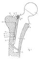
- the collar 3 On its upper side 16 facing the shaft head 1, the collar 3 opens into an annular depression 17 from which the shaft head 1 with its spherical surface 18 rises.
- This spherical surface 18 is rotatably supported in a hip socket, not shown, which is embedded in a pelvic bone, also not shown.
- a recess 19 extends through the shaft 2, which extends in the form of a secant through the outer radius of curvature 11.
- This secant begins approximately in the region of the opening of the outer radius of curvature 11 into the collar 3 and ends in a region in which the outer radius of curvature 11 opens into a straight end piece 2o which extends in the direction of the lower end 9 of the shaft part.
- This straight end piece 2o has a length that is approximately 1.5 times greater than the outer curvature 11.
- the recess 19 is designed as a cavity 21 which is open on its side facing the outer radius of curvature 11. This cavity 21 has a different depth in its cross section.
- This depth is the smallest in the area of the collar 3 and at an end 22 of the cavity 21 opposite the collar. Between the collar 3 and the end 22, the depth of the cavity 21 passes through a maximum 23. In the area of this maximum 23, opposite side walls 24, 25 of the cavity 21 are formed the highest. These side walls 24, 25 converge in the interior of the shaft 2 to form an arc 26 which is opposite an opening 27 of the recess 19.
- a clamping device 28 is guided in this cavity 21.
- This consists essentially of a pull rod 29 and a shield 3o, which is coupled to the pull rod 29 via a catch 31.
- This driver catch 31 is attached to the pull rod 29.
- the driver catch 31 is fastened to a lower end 32 of the pull rod 29 facing away from the collar 3.
- the driver catch 31 is designed in the form of a tooth 33 which extends on the driver catch 31 in a direction facing away from the circular arc 26. This tooth 33 rises in a direction of the pull rod 29 facing away from the end 32.
- the pull rod can be cylindrical, for example, and projects with its upper end 34 facing away from the lower end 32 through a bore 35 provided in the collar 3. This bore 35 extends in the direction of the cavity 21 through the collar 3.
- the bore 35 is widened to form a seat 37.
- This seat is so far embedded in the collar 3 that 3 lateral walls 38 are formed within the collar, on which an elastic intermediate layer 39 is guided is.
- This elastic intermediate layer 39 can consist, for example, of a silicone.
- the upper end 34 of the pull rod 29 projects through this elastic intermediate layer 39 and is supported on the elastic intermediate layer 39 by means of a washer 40 with a clamping nut 41.
- the bore 35 surrounds the pull rod 29 with a play that is large enough to allow movements of the pull rod 29 which are transverse to the longitudinal direction of the pull rod. Such movements are absorbed by the elastic intermediate layer 39.
- the bore 35 is expediently designed in the form of a cone which widens in the direction of the cavity 21, so that the pull rod can carry out pivotal movements within the cavity 21 about its upper end 34.
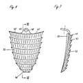
- the shield 3o is provided on its outer surface 42 facing away from the pull rod 29 with teeth 43 which extend in mutually parallel rows transverse to the longitudinal direction of the pull rod 29. These teeth 43 rise with their cutting edges 44 in the direction of the upper end 34 of the pull rod 29.
- the shield 3o is curved in the form of an arc around the pull rod 29. In this way, it receives a curvature 45, which allows the shield 3o to be in large contact with a marrow cavity prepared for receiving the shaft 2.
- the shield 30 With its lower end 46 facing away from the upper end 34, the shield 30 lies on the catch 31. In the direction of its upper end 47, the shield 3o widens like a shield. At the upper end 47 an eyelet 48 is provided which lies approximately on a center line extending through the shield 3o. A bore 49 extends through this eyelet 48, the cross section of which is dimensioned such that the pull rod 29 can pass through it with play.
- the shield 3o with bearing surfaces 5o, 51 rests on the shaft 2 on both sides of the cavity 21. Along these contact surfaces 51 the shield 3o slides in the longitudinal direction of the shaft 2 when it is raised in the direction of the collar 3 with the aid of the pull rod 29.
- two pressure surfaces 52, 53 are formed on the shaft, on which the bearing surfaces 5o, 51 rest. These pressure surfaces 52, 53 are formed at at least two points as inclined planes 54, 55, which rise in the direction of the shield 3o. The elevations of the inclined planes 54, 55 run in the direction of the collar 3.
- the shield 3o coupled to the pull rod 29 via the driver catch 31 is raised with this in the direction of the collar 3, the shield 3o with its contact surfaces 5o, 51 runs on the inclined planes 54, 55 applied to the pressure surfaces 52, 53, so that the shield 3o executes a tilting movement directed away from the pull rod 29 around its lower end 46. It is guided in the longitudinal direction of the pull rod 29 on the eyelet 48. This tilting movement gives the teeth 43 an inclination in the direction of the medullary cavity extending through the femur 13, in the walls of which they can burrow when the clamping nut 41 is further tightened. In this way, a tensioning force which braces the shaft 2 in the medullary cavity is exerted by the medullary cavity on the shaft 2 via the shield 30 and the pull rod 29.
- the collar 3 lies firmly with the teeth 12 on a support surface 56 prepared on the femur 13. These teeth 12 dig into the bearing surface 56 and in this way prevent the shaft part 13 from being able to perform pivoting movements around its end 9 within the medullary cavity of the femur 13.
- 2 grooves 57 are provided in the shaft 2 for further guidance of the shaft anchored in the marrow cavity without cement. These grooves 57 run parallel to one another in the longitudinal direction of the shaft 2.
- the direction of the lower end piece 2o is provided as the longitudinal direction of the shaft 2, the grooves 57 of which extend parallel to the outer surface 58 facing the outer radius of curvature 11.
- the grooves 57 have approximately the same mutually Widths.
- Sharp edges 59 are formed between the individual grooves 57, which cut into the femur 13 when the shaft 2 is inserted into the medullary cavity. In this way, the shaft 2 receives a fixed alignment with respect to the thigh bone 13, without the rotational forces or swiveling movements within the thigh bone 13 being able to be carried out by the forces introduced into the shaft head 1.
- the grooves 57 not only run parallel to one another, but are also aligned in a straight line.
- a correspondingly large recess is first prepared in the area of the medullary cavity.
- the shaft 2 is then inserted into the prepared medullary cavity.
- Both the tie rod 29 and the shield 3o have their respective lower ends 32, 46 inserted as far as possible into the cavity 21.
- the shield 3o lies with its support surfaces 5o, 51 on the pressure surfaces 52, 53 in an area which extends in the direction of the end 46 of the shield 3o below the inclined planes 54, 55.
- the clamping nut 41 is screwed in the direction of the elastic intermediate layer 39 so that a pull is exerted on the pull rod 29.
- the shield 3o runs with its contact surfaces 5o, 51 over the pressure surfaces 52, 53 and reaches the area of the inclined planes 54, 55.
- the inclined planes 54, 55 lift the shield 3o in the direction of the marrow cavity adjacent to the teeth 43, see above that the teeth claw firmly in the medullary cavity of the femur 13 when tightening the clamping nut 41 further.
- the bore 35 which is designed in the form of a cone, permits such pendulum movements of the pull rod 29.
- deformations in the area of the clamping nut 41 can be absorbed by the elastic intermediate layer 39 .
- the recess 19 can also be designed as a closed bore in the direction of the side 7 of the shaft 2. It is only important that the cavity at its lower end 22 is so open due to the formation of the outer radius of curvature 11 that a displacement of the driver catch 31 is possible. This shift must be able to take place over a length that allows the shield 3o to be braced within the marrow cavity.
Landscapes
- Health & Medical Sciences (AREA)
- Orthopedic Medicine & Surgery (AREA)
- Cardiology (AREA)
- Oral & Maxillofacial Surgery (AREA)
- Transplantation (AREA)
- Engineering & Computer Science (AREA)
- Biomedical Technology (AREA)
- Heart & Thoracic Surgery (AREA)
- Vascular Medicine (AREA)
- Life Sciences & Earth Sciences (AREA)
- Animal Behavior & Ethology (AREA)
- General Health & Medical Sciences (AREA)
- Public Health (AREA)
- Veterinary Medicine (AREA)
- Prostheses (AREA)
- Compounds Of Unknown Constitution (AREA)
- Surgical Instruments (AREA)
Claims (29)
- partie tige d'une articulation de hanche, comprenant une tête sensiblement sphérique (1) et une tige (2) qui se raccorde à cette tête par l'intermédiaire d'une collerette (3) et qui, à la suite de la collerette (3) présente une courbure (8) en direction de son extrémité inférieure (9), et peut être fixée, au moyen d'un dispositif de serrage (28) réalisé sous la forme d'un tirant (29), dans le canal médullaire d'un fémur (13), caractérisée en ce que la tige (2) présente, dans sa surface, des rainures (57) s'étendant en ligne droite dans sa direction longitudinale, destinées à établir une liaison par sûreté de forme avec la masse osseuse qui entoure la surface de la tige, et en ce que la tige (2) peut être bloquée dans le canal médullaire à son extrémité supérieure voisine de la collerette (3), au moyen du dispositif de serrage (28) réalisé sous la forme d'un tirant (29), lequel dispositif de serrage peut prendre appui, dans l'état serré contre la tige (2) d'une part et contre le canal médullaire, d'autre part.
- Partie tige selon la revendication 1, caractérisée en ce que le tirant (29) servant à appliquer une force de serrage présente une extrémité de serrage qui s'étend à travers un perçage (35) de la collerette (3), un écrou de serrage (41) vissé sur l'extrémité de serrage prenant appui sur la surface du perçage qui est à l'opposé de la tige (2).
- Partie tige selon la revendication 2, caractérisée en ce que le perçage (35) présente une fente longitudinale qui s'élargit en forme de cône en direction de l'extrémité de la tige (2).
- Partie tige selon l'une des revendications 2 et 3, caractérisée en ce que l'écrou de serrage (41) prend appui sur une surface de portée (37) qui le soutient par une grande surface et qui est formé dans la collerette (3) transversalement à la direction longitudinale du tirant (29).
- Partie tige selon la revendication 4, caractérisée en ce qu'une couche intercalaire élastique (39) est interposée entre la surface de portée (37) et l'écrou de serrage (41).
- Partie tige selon la revendication 5, caractérisée en ce que la surface de portée (37) est prévue à l'extrémité d'une chambre ménagée dans la collerette (13), et qui reçoit à la fois la couche intercalaire (39) et l'écrou de serrage (41).
- Partie tige selon l'une des revendications 1 à 6, caractérisé en ce que le tirant (29) s'étend à travers un évidement (19) de la tige (2) qui s'étend dans sa direction longitudinale.
- Partie tige selon la revendication 7, caractérisée en ce que l'évidement (19) est constitué par une gorge (21) qui présente une section transversale sensiblement en U et est ouverte sur une surface extérieure (58) de la tige (2) qui est dirigée vers elle.
- Partie tige selon la revendication 8, caractérisée en ce que la gorge (21) reçoit le tirant (29).
- Partie tige selon l'une des revendications 8 et 9, caractérisée en ce que, dans la gorge (21), est formé un plan incliné qui presse le tirant (29) contre le canal médullaire lorsqu'on le serre, plan qui s'élève sur un fond de la gorge qui est le plus éloigné de la surface externe (58) de la tige (2) et présente une pente montante en direction de la tête (1) de la tige.
- Partie tige selon l'une des revendications 8 à 10, caractérisée en ce que, sur le tirant (29), est prévu un plan incliné dirigé vers le plan incliné formé sur le fond de la gorge (21) et les pentes montantes des plans inclinés se correspondent mutuellement.
- Partie tige selon l'une des revendications 7 à 11, caractérisée en ce que l'évidement (19) est constitué par un perçage qui se raccorde directement au perçage (35) prévu dans la collerette (3) et est formé, en direction de l'extrémité (9) de la tige (2), immédiatement au-dessous de la courbure (8), sous la forme d'une gorge s'ouvrant dans la surface de la tige (2).
- Partie tige selon l'une des revendications 1 à 12, caractérisée en ce que le tirant (29) présente une surface de pression dirigée vers le canal médullaire dans sa partie qui est à l'opposé de la tige (2).
- Partie tige selon la revendication 13, caractérisée en ce que la surface de pression présente la forme de protubérances dont chacune présente une arête tranchante vive, dirigée vers le canal médullaire.
- Partie tige selon la revendication 14, caractérisée en ce que les protubérances sont constituées par des dents dont les arêtes tranchantes font saillie sur la surface du tirant (29) qui est dirigée vers le canal médullaire.
- Partie tige selon la revendication 15, caractérisée en ce que les dents s'étendent transversalement à la direction longitudinale du tirant (29) sur la largeur de ce dernier.
- Partie tige selon la revendication 15, caractérisée en ce que les dents s'étendent, directement à la suite l'une de l'autre, sur toute la surface du tirant (29) qui forme une surface de pression.
- Partie tige selon la revendication 15, caractérisée en ce que les dents (43) sont formées sur une plaque (30) qui s'étend sur la surface de pression du tirant (29).
- Partie tige selon la revendication 18, caractérisée en ce que la plaque (30) repose sur un mentonnet d'entraînement (31) qui est fixé à une extrémité inférieure (32) du tirant (29) qui est la plus éloignée de l'écrou de serrage (41), et émerge de la gorge (21).
- Partie tige selon l'une des revendications 18 et 19, caractérisée en ce que la plaque (30) prend appui par sa face arrière dirigée vers le tirant (29) sur des surfaces de portée (50, 51) qui sont formées des deux côtés du tirant (29) sur une surface externe qui délimite la tige (2).
- Partie tige selon la revendication 20, caractérisée en ce que chacune des deux surfaces de portée présente au moins un plan incliné (54, 55) qui s'élève vers la collerette (3), sur lequel la plaque (30) prend appui par des surfaces de pression (52, 53).
- Partie tige selon la revendication 21, caractérisée en ce que les surfaces de pression (52, 53) sont formées sur le dos de la plaque (30) qui est dirigée vers la tige (2) et sont présentées sous la forme de plans inclinés qui sont adaptés aux plans inclinés (54, 55) qui sont formés sur les surfaces de portée (50, 51).
- Partie tige selon la revendication 22, caractérisée en ce que les plans inclinés formés sur les surfaces de pression (52, 53) de la plaque (30) présentent une pente montante en direction de l'extrémité inférieure (46) de la plaque (30) qui est la plus éloignée de l'écrou de serrage (41).
- Partie tige selon la revendication 23, caractérisée en ce que la plaque (30) présente un oeillet (48) à son extrémité supérieure (47) qui est la plus éloignée de son extrémité inférieure (46).
- Partie tige selon l'une des revendications 22 à 24, caractérisée en ce que la plaque (30) présente un bombé en direction de la tige (2) et se rétrécit en direction de son extrémité inférieure (46) pour présenter la forme d'un écusson.
- Partie tige selon l'une des revendications 1 à 25, caractérisée en ce que la collerette (3) est munie, sur sa face inférieure dirigée vers la tige (2), d'arêtes tranchantes qui sont dirigées vers une surface de portée (56) et est appuyée sur celle de la collerette (3) par sa face intérieure.
- Partie de tige selon la revendication 26, caractérisée en ce que les arêtes tranchantes forment des dents (12).
- Partie tige selon la revendication 27, caractérisée en ce que chaque dent (12) présente une dimension longitudinale qui s'étend transversalement à la direction d'un plan imaginaire sous-tendu par la courbure (8) de la tige (2).
- Partie tige selon l'une des revendications 27 et 28, caractérisée en ce que chaque dent (12) présente sur son flanc dirigé vers un rayon de courbure intérieur (10) de la courbure (8), une pente montante plus raide que sur son autre flanc.
Priority Applications (1)
| Application Number | Priority Date | Filing Date | Title |
|---|---|---|---|
| AT86110508T ATE77927T1 (de) | 1985-08-06 | 1986-07-30 | Schaftteil eines hueftgelenkes. |
Applications Claiming Priority (2)
| Application Number | Priority Date | Filing Date | Title |
|---|---|---|---|
| DE3528151 | 1985-08-06 | ||
| DE19853528151 DE3528151A1 (de) | 1985-08-06 | 1985-08-06 | Schaftteil eines hueftgelenkes |
Publications (3)
| Publication Number | Publication Date |
|---|---|
| EP0222979A2 EP0222979A2 (fr) | 1987-05-27 |
| EP0222979A3 EP0222979A3 (en) | 1988-05-04 |
| EP0222979B1 true EP0222979B1 (fr) | 1992-07-08 |
Family
ID=6277812
Family Applications (1)
| Application Number | Title | Priority Date | Filing Date |
|---|---|---|---|
| EP86110508A Expired - Lifetime EP0222979B1 (fr) | 1985-08-06 | 1986-07-30 | Partie fémorale d'une articulation de la hanche |
Country Status (3)
| Country | Link |
|---|---|
| EP (1) | EP0222979B1 (fr) |
| AT (1) | ATE77927T1 (fr) |
| DE (2) | DE3528151A1 (fr) |
Families Citing this family (10)
| Publication number | Priority date | Publication date | Assignee | Title |
|---|---|---|---|---|
| FR2606997A1 (fr) * | 1986-08-25 | 1988-05-27 | Gilles Crespy | Prothese femorale mecanique auto-bloquee et procede de mise en oeuvre |
| EP0266081B1 (fr) * | 1986-10-25 | 1992-01-02 | Gallinaro, Paolo | Prothèse pour la hanche |
| DE3701198A1 (de) * | 1987-01-15 | 1988-07-28 | Buse Harry | Hueftschaft-implantat |
| DE8703465U1 (de) * | 1987-03-07 | 1987-04-16 | Kuenne, Hermann, Dr.Med., 4782 Erwitte | Hüftgelenk-Endoprothese |
| FR2620022A1 (fr) * | 1987-09-08 | 1989-03-10 | Teinturier Pierre | Prothese articulaire totale, notamment de la hanche |
| DE3730814A1 (de) * | 1987-09-14 | 1989-03-23 | Gernot Dr Med Felmet | Zementfrei implantierbarer, selbstnachspannender hueftgelenkschaft |
| US4936863A (en) * | 1988-05-13 | 1990-06-26 | Hofmann Aaron A | Hip prosthesis |
| DE3912753A1 (de) * | 1989-04-19 | 1990-10-25 | Joachim Dr Moebius | Oberschenkelteil einer hueftgelenk-endoprothese |
| FR2647335A1 (fr) * | 1989-05-23 | 1990-11-30 | Bousquet Gilles | Tige intramedullaire pour prothese vissee |
| CN121196809B (zh) * | 2025-11-28 | 2026-01-27 | 安徽省立医院(中国科学技术大学附属第一医院) | 用于固定股骨大转子截骨块的股骨柄假体 |
Family Cites Families (7)
| Publication number | Priority date | Publication date | Assignee | Title |
|---|---|---|---|---|
| DE8411765U1 (de) * | 1984-09-27 | Howmedica International, Inc., 2301 Schönkirchen | Hüftgelenkendoprothese | |
| FR1278359A (fr) * | 1961-01-13 | 1961-12-08 | Maison Drapier | Perfectionnement aux prothèses fémorales |
| DE2611985C3 (de) * | 1976-03-20 | 1981-08-13 | Baumann, Friedrich, Prof. Dr.Med., 8858 Neuburg | Hüftkopf-Endoprothese |
| DE2832555A1 (de) * | 1978-07-25 | 1980-02-07 | Sigri Elektrographit Gmbh | Hueftgelenkprothese |
| DE2839093C3 (de) * | 1978-09-08 | 1981-10-01 | Reimer, Hans, Dr., 5609 Hückeswagen | Oberschenkelteil einer Hüftgelenkendoprothese |
| FR2529077B1 (fr) * | 1982-06-29 | 1985-01-18 | Lord Gerald | Nouvelle prothese osseuse et son obtention |
| EP0145939A3 (fr) * | 1983-11-30 | 1985-07-24 | Protek AG | Prothèse intramédullaire non scellée en forme de lame pour articulation de la hanche |
-
1985
- 1985-08-06 DE DE19853528151 patent/DE3528151A1/de not_active Withdrawn
-
1986
- 1986-07-30 DE DE8686110508T patent/DE3685940D1/de not_active Expired - Fee Related
- 1986-07-30 AT AT86110508T patent/ATE77927T1/de not_active IP Right Cessation
- 1986-07-30 EP EP86110508A patent/EP0222979B1/fr not_active Expired - Lifetime
Also Published As
| Publication number | Publication date |
|---|---|
| EP0222979A2 (fr) | 1987-05-27 |
| DE3685940D1 (de) | 1992-08-13 |
| ATE77927T1 (de) | 1992-07-15 |
| DE3528151A1 (de) | 1987-02-19 |
| EP0222979A3 (en) | 1988-05-04 |
Similar Documents
| Publication | Publication Date | Title |
|---|---|---|
| DE4435497C1 (de) | Modulares Knochenimplantat mit Pfanne und Stiften | |
| EP1415621B1 (fr) | Prothèse de l'épaule | |
| DE69423031T2 (de) | Vorrichtung zur Zusammenfügung von Knochenbrüchen im oberen Femurende | |
| DE69320593T2 (de) | Knochenplattensystem | |
| EP0845251B1 (fr) | Eléments de construction pour une prothèse de tête fémorale modulaire, en particulier une prothèse de réopération, et prothèse de tête fémorale obtenue avec detels éléments | |
| EP0942692B1 (fr) | Partie femorale d'une prothese de l'articulation du genou | |
| DE69626006T2 (de) | Tibiale prothese | |
| DE69729608T2 (de) | Befestigungssystem für eine modulare Knieprothese | |
| DE69512497T2 (de) | Sphärische Oberarmprothese | |
| DE3874754T2 (de) | Gelenkprothese. | |
| EP2023862B1 (fr) | Prothèse d'épaule dotée d'une pièce en saillie sur la plaque de base | |
| DE19802229C2 (de) | Plattenförmiger Riegel zur Ruhigstellung einer Fraktur des Beckens | |
| EP0243298B1 (fr) | Eléments de construction d'une prothèse fémorale avec tige | |
| DE69514257T2 (de) | Implantat für die Behandlung von Frakturen des Femur | |
| DE69715141T2 (de) | Orthopedische Prothese mit Knochenschrauben und Zement | |
| EP0279830B1 (fr) | Endoprothese a structure modulaire pour remplacer une partie du bassin dans la region de la hanche | |
| DE69403347T2 (de) | Ganzknieprothese sowie entsprechender modularer knieprothesenbausatz | |
| DE3722853C2 (fr) | ||
| WO1992020298A1 (fr) | Implant a surface de pression | |
| EP0711132A1 (fr) | Plaque vissee bifurquee | |
| EP0540559A1 (fr) | Prothese vertebrale | |
| EP0134406A2 (fr) | Tige de soutien intramédullaire | |
| EP0222979B1 (fr) | Partie fémorale d'une articulation de la hanche | |
| DE3426947C2 (de) | Oberschenkelteil einer Hüftgelenk-Endoprothese | |
| DE29916202U1 (de) | Repositionsvorrichtung |
Legal Events
| Date | Code | Title | Description |
|---|---|---|---|
| PUAI | Public reference made under article 153(3) epc to a published international application that has entered the european phase |
Free format text: ORIGINAL CODE: 0009012 |
|
| AK | Designated contracting states |
Kind code of ref document: A2 Designated state(s): AT BE CH DE FR GB IT LI LU NL SE |
|
| PUAL | Search report despatched |
Free format text: ORIGINAL CODE: 0009013 |
|
| AK | Designated contracting states |
Kind code of ref document: A3 Designated state(s): AT BE CH DE FR GB IT LI LU NL SE |
|
| 17P | Request for examination filed |
Effective date: 19881017 |
|
| 17Q | First examination report despatched |
Effective date: 19900322 |
|
| GRAA | (expected) grant |
Free format text: ORIGINAL CODE: 0009210 |
|
| AK | Designated contracting states |
Kind code of ref document: B1 Designated state(s): AT BE CH DE FR GB IT LI LU NL SE |
|
| PG25 | Lapsed in a contracting state [announced via postgrant information from national office to epo] |
Ref country code: IT Free format text: LAPSE BECAUSE OF FAILURE TO SUBMIT A TRANSLATION OF THE DESCRIPTION OR TO PAY THE FEE WITHIN THE PRE;WARNING: LAPSES OF ITALIAN PATENTS WITH EFFECTIVE DATE BEFORE 2007 MAY HAVE OCCURRED AT ANY TIME BEFORE 2007. THE CORRECT EFFECTIVE DATE MAY BE DIFFERENT FROM THE ONE RECORDED.SCRIBED TIME-LIMIT Effective date: 19920708 Ref country code: NL Effective date: 19920708 Ref country code: SE Effective date: 19920708 Ref country code: BE Effective date: 19920708 |
|
| REF | Corresponds to: |
Ref document number: 77927 Country of ref document: AT Date of ref document: 19920715 Kind code of ref document: T |
|
| PG25 | Lapsed in a contracting state [announced via postgrant information from national office to epo] |
Ref country code: AT Effective date: 19920730 |
|
| PG25 | Lapsed in a contracting state [announced via postgrant information from national office to epo] |
Ref country code: LU Free format text: LAPSE BECAUSE OF NON-PAYMENT OF DUE FEES Effective date: 19920731 |
|
| REF | Corresponds to: |
Ref document number: 3685940 Country of ref document: DE Date of ref document: 19920813 |
|
| GBT | Gb: translation of ep patent filed (gb section 77(6)(a)/1977) | ||
| ET | Fr: translation filed | ||
| NLV1 | Nl: lapsed or annulled due to failure to fulfill the requirements of art. 29p and 29m of the patents act | ||
| PLBE | No opposition filed within time limit |
Free format text: ORIGINAL CODE: 0009261 |
|
| STAA | Information on the status of an ep patent application or granted ep patent |
Free format text: STATUS: NO OPPOSITION FILED WITHIN TIME LIMIT |
|
| 26N | No opposition filed | ||
| REG | Reference to a national code |
Ref country code: GB Ref legal event code: IF02 |
|
| REG | Reference to a national code |
Ref country code: GB Ref legal event code: 732E |
|
| REG | Reference to a national code |
Ref country code: CH Ref legal event code: PUE Owner name: WALDEMAR LINK (GMBH & CO.) Free format text: GMT GESELLSCHAFT FUER MEDIZINISCHE TECHNIK MBH#HOLSTENSTRASSE 2#HAMBURG 50 (DE) -TRANSFER TO- WALDEMAR LINK (GMBH & CO.)#BARKHAUSENWEG 10#22339 HAMBURG (DE) Ref country code: CH Ref legal event code: NV Representative=s name: ISLER & PEDRAZZINI AG |
|
| PGFP | Annual fee paid to national office [announced via postgrant information from national office to epo] |
Ref country code: GB Payment date: 20030710 Year of fee payment: 18 |
|
| PGFP | Annual fee paid to national office [announced via postgrant information from national office to epo] |
Ref country code: FR Payment date: 20030721 Year of fee payment: 18 |
|
| PGFP | Annual fee paid to national office [announced via postgrant information from national office to epo] |
Ref country code: CH Payment date: 20030728 Year of fee payment: 18 |
|
| PGFP | Annual fee paid to national office [announced via postgrant information from national office to epo] |
Ref country code: DE Payment date: 20030923 Year of fee payment: 18 |
|
| REG | Reference to a national code |
Ref country code: FR Ref legal event code: TP |
|
| PG25 | Lapsed in a contracting state [announced via postgrant information from national office to epo] |
Ref country code: GB Free format text: LAPSE BECAUSE OF NON-PAYMENT OF DUE FEES Effective date: 20040730 |
|
| PG25 | Lapsed in a contracting state [announced via postgrant information from national office to epo] |
Ref country code: CH Free format text: LAPSE BECAUSE OF NON-PAYMENT OF DUE FEES Effective date: 20040731 Ref country code: LI Free format text: LAPSE BECAUSE OF NON-PAYMENT OF DUE FEES Effective date: 20040731 |
|
| PG25 | Lapsed in a contracting state [announced via postgrant information from national office to epo] |
Ref country code: DE Free format text: LAPSE BECAUSE OF NON-PAYMENT OF DUE FEES Effective date: 20050201 |
|
| REG | Reference to a national code |
Ref country code: CH Ref legal event code: PL |
|
| GBPC | Gb: european patent ceased through non-payment of renewal fee |
Effective date: 20040730 |
|
| PG25 | Lapsed in a contracting state [announced via postgrant information from national office to epo] |
Ref country code: FR Free format text: LAPSE BECAUSE OF NON-PAYMENT OF DUE FEES Effective date: 20050331 |
|
| REG | Reference to a national code |
Ref country code: FR Ref legal event code: ST |