EP0223009A2 - Dispositif opto-électronique de mesure de position - Google Patents
Dispositif opto-électronique de mesure de position Download PDFInfo
- Publication number
- EP0223009A2 EP0223009A2 EP86112833A EP86112833A EP0223009A2 EP 0223009 A2 EP0223009 A2 EP 0223009A2 EP 86112833 A EP86112833 A EP 86112833A EP 86112833 A EP86112833 A EP 86112833A EP 0223009 A2 EP0223009 A2 EP 0223009A2
- Authority
- EP
- European Patent Office
- Prior art keywords
- grating
- scanning
- assigned
- measuring device
- phase
- Prior art date
- Legal status (The legal status is an assumption and is not a legal conclusion. Google has not performed a legal analysis and makes no representation as to the accuracy of the status listed.)
- Granted
Links
- 230000005693 optoelectronics Effects 0.000 title 1
- 230000003287 optical effect Effects 0.000 claims description 10
- 230000003595 spectral effect Effects 0.000 claims description 2
- 230000005855 radiation Effects 0.000 description 4
- 230000010363 phase shift Effects 0.000 description 3
- 238000011109 contamination Methods 0.000 description 2
- 238000011156 evaluation Methods 0.000 description 2
- 239000012634 fragment Substances 0.000 description 2
- 238000001514 detection method Methods 0.000 description 1
- 238000006073 displacement reaction Methods 0.000 description 1
- 230000000694 effects Effects 0.000 description 1
- 239000000835 fiber Substances 0.000 description 1
- 238000000034 method Methods 0.000 description 1
- 238000012634 optical imaging Methods 0.000 description 1
- 230000035945 sensitivity Effects 0.000 description 1
Images

Classifications
-
- G—PHYSICS
- G01—MEASURING; TESTING
- G01D—MEASURING NOT SPECIALLY ADAPTED FOR A SPECIFIC VARIABLE; ARRANGEMENTS FOR MEASURING TWO OR MORE VARIABLES NOT COVERED IN A SINGLE OTHER SUBCLASS; TARIFF METERING APPARATUS; MEASURING OR TESTING NOT OTHERWISE PROVIDED FOR
- G01D5/00—Mechanical means for transferring the output of a sensing member; Means for converting the output of a sensing member to another variable where the form or nature of the sensing member does not constrain the means for converting; Transducers not specially adapted for a specific variable
- G01D5/26—Mechanical means for transferring the output of a sensing member; Means for converting the output of a sensing member to another variable where the form or nature of the sensing member does not constrain the means for converting; Transducers not specially adapted for a specific variable characterised by optical transfer means, i.e. using infrared, visible, or ultraviolet light
- G01D5/32—Mechanical means for transferring the output of a sensing member; Means for converting the output of a sensing member to another variable where the form or nature of the sensing member does not constrain the means for converting; Transducers not specially adapted for a specific variable characterised by optical transfer means, i.e. using infrared, visible, or ultraviolet light with attenuation or whole or partial obturation of beams of light
- G01D5/34—Mechanical means for transferring the output of a sensing member; Means for converting the output of a sensing member to another variable where the form or nature of the sensing member does not constrain the means for converting; Transducers not specially adapted for a specific variable characterised by optical transfer means, i.e. using infrared, visible, or ultraviolet light with attenuation or whole or partial obturation of beams of light the beams of light being detected by photocells
- G01D5/36—Forming the light into pulses
- G01D5/38—Forming the light into pulses by diffraction gratings
Definitions
- the invention relates to a photoelectric position measuring device according to the preamble of claim 1.
- Position measuring devices that work with phase gratings are known for example from DE-AS 15 48 707 and DE-OS 23 16 248.
- the applicant's previously unpublished European patent application No. 85301077.5 describes a position measuring device in which it is proposed to generate a phase shift between the beams of rays diffracted at the index grating in such a way that, with the grating constant opposite, the width of a ridge of the index grating formed as a phase grating from that Width of a furrow deviates, so that the web / furrow ratio deviates from 1: 1.
- the degrees of modulation of the signals of zero and t first order in incident light phase grating measuring systems with parallel arranged index and scale grids with unevenly wide ridges or furrows of the index grating are different and change unevenly when the distance changes, contamination of the grating etc.
- the object of the invention is to reduce the sensitivity to changes in distance, deviations from the parallelism of the grating, contamination and the like in position measuring devices of this type.
- the advantages of the position measuring device according to the invention lie in the simple generation of the phase-shifted scanning signals for direction detection in connection with the simple generation of push-pull signals and their electrical combination for the compensation of scanning interference.
- light used below includes ultraviolet and infrared radiation as well as radiation in the visible range.
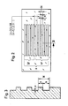
- a length measuring device 1 is shown according to the so-called three-grating incident light principle.
- the radiation from a light source L is collimated by a condenser 2 and diffracted and reflected at phase gratings A and B.
- phase grating B With phase grating B, the ratio of web width to furrow width is. 1: 1; it represents the scale grating.
- the scanning grating A is formed by two scanning fields AF and A designed as a phase grating.
- the web-groove-width ratio a: b of the scanning fields AF and A F deviates from 1: 1, which is particularly evident from FIGS. 2 and 3.
- phase gratings of the scale grating B and the scanning grating A have the same grating constant GK.
- the scale grid B and the scanning grid A are arranged parallel to one another and the scale grid B is displaceable in this parallel plane perpendicular to the course of the graduation marks.
- the radiation emanating from the light source L is diffracted by the first (scanning) grating A and the second (scale) grating B in the direction of light and reunited at the scanning grating A and brought to interference.
- the ridge / groove width ratios differ with these two grids.
- the scale grating B the ridge / groove width ratio is 1: 1, with the scanning grating it is at for example 1: 1.5. This measure leads to the fact that the diffracted partial beams of different diffraction orders are shifted in their phase relation to each other.
- the direction of the relative movement between the scanning grating A and the scale grating B can be determined from the phase-shifted partial beams which fall on the photodetectors D-1, D0, D + 1, which is indicated by the web / groove width Ratio of the scanning grating A is made possible (see FIG. 3).
- the scanning grating A is also provided with selectively acting optical means K1, K2 which, in cooperation with the two scanning fields AF and A F, enable partial beams of rays to be generated in phase opposition to the aforementioned partial beams.
- the scanning fields AF and AF are offset from one another in the measuring direction by a fraction, for example 1/4 of the lattice constants GK.
- the individual scanning fields AF or AF are assigned to prisms K2 and K1, which deflect the partial beams in opposite directions.
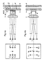
- FIG. 4a shows the position measuring device already known from FIG. 1, of which a top view is shown in FIG. 4b.
- FIG. 4b shows that the two prisms K1 and K2, which are assigned to the scanning fields AF and AF, have the partial-phase partial beams on the associated photodetectors D0 , D + 1 , D-1 and D0, D + 1, D-1 steer.
- the arrangement of the photo detectors DO , D + 1 , D-1 and D0, D + 1, D-1 each show the left part of FIGS. 4a and 4b, the focal plane of the condenser 2 being folded into the plane of the drawing. In reality, it is perpendicular to the plane of the drawing.
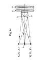
- FIG. 4c A particularly advantageous embodiment of the invention is shown in FIG. 4c, which has also been highly schematic.
- two lenses Z1 and Z2, arranged in opposite directions, become the scanning fields AF and AF assigned to collimate the light and to the corresponding photodetectors D0 , D + 1 D-1 ; Deflect D0, D + 1, D-1. Since the position of the photodetectors mentioned corresponds in principle to the illustration in FIG. 4b, a separate drawing has been omitted. Due to the arrangement of the decentred lenses Z1 and Z2 described, the condenser can be omitted.
- the selectively acting optical means can be formed by components with different spectral and / or polarization-optical properties, to which the photodetectors must of course be matched.
- the photodetectors DO and D 0 are connected antiparallel.
- a stable phase shift of 90 ° to the 0 ° signal is obtained when D + 1 is connected from the anti-parallel connection of the photo elements D + 1 and the anti-parallel interconnection of D-1 with
Landscapes
- Physics & Mathematics (AREA)
- General Physics & Mathematics (AREA)
- Optical Transform (AREA)
- Length Measuring Devices By Optical Means (AREA)
- Radar Systems Or Details Thereof (AREA)
- Transmission And Conversion Of Sensor Element Output (AREA)
Priority Applications (1)
| Application Number | Priority Date | Filing Date | Title |
|---|---|---|---|
| AT86112833T ATE65839T1 (de) | 1985-11-21 | 1986-09-17 | Lichtelektrische positionsmesseinrichtung. |
Applications Claiming Priority (2)
| Application Number | Priority Date | Filing Date | Title |
|---|---|---|---|
| DE3541199 | 1985-11-21 | ||
| DE3541199A DE3541199C1 (de) | 1985-11-21 | 1985-11-21 | Lichtelektrische Positionsmesseinrichtung |
Publications (3)
| Publication Number | Publication Date |
|---|---|
| EP0223009A2 true EP0223009A2 (fr) | 1987-05-27 |
| EP0223009A3 EP0223009A3 (en) | 1989-03-22 |
| EP0223009B1 EP0223009B1 (fr) | 1991-07-31 |
Family
ID=6286494
Family Applications (1)
| Application Number | Title | Priority Date | Filing Date |
|---|---|---|---|
| EP86112833A Expired - Lifetime EP0223009B1 (fr) | 1985-11-21 | 1986-09-17 | Dispositif opto-électronique de mesure de position |
Country Status (5)
| Country | Link |
|---|---|
| US (1) | US4766310A (fr) |
| EP (1) | EP0223009B1 (fr) |
| JP (1) | JPS62121314A (fr) |
| AT (1) | ATE65839T1 (fr) |
| DE (2) | DE3541199C1 (fr) |
Cited By (11)
| Publication number | Priority date | Publication date | Assignee | Title |
|---|---|---|---|---|
| GB2216650A (en) * | 1988-01-22 | 1989-10-11 | Mitutoyo Corp | Optical encoder |
| GB2246430A (en) * | 1988-01-22 | 1992-01-29 | Mitutoyo Corp | Optical encoder |
| EP0509979A3 (en) * | 1991-04-18 | 1993-01-20 | Rsf-Elektronik Gesellschaft M.B.H. | Photo-electronic position-measuring device |
| EP0548848A1 (fr) * | 1991-12-20 | 1993-06-30 | Canon Kabushiki Kaisha | Dispositif pour mesurer un déplacement |
| US5390022A (en) * | 1992-04-07 | 1995-02-14 | Canon Kabushiki Kaisha | Displacement information detection apparatus for receiving a divergent light beam |
| US5483377A (en) * | 1992-12-24 | 1996-01-09 | Canon Kabushiki Kaisha | Displacement detection apparatus |
| DE19507613A1 (de) * | 1995-03-04 | 1996-09-05 | Heidenhain Gmbh Dr Johannes | Längen- oder Winkelmeßeinrichtung |
| US5574559A (en) * | 1992-12-28 | 1996-11-12 | Canon Kabushiki Kaisha | Displacement detection apparatus using multiple displacement detection signals formed by a multiple phase combination grating |
| EP0720005A3 (fr) * | 1994-12-27 | 1997-01-15 | Canon Kk | Capteur optique |
| WO1998016802A1 (fr) * | 1996-10-16 | 1998-04-23 | Dr. Johannes Heidenhain Gmbh | Indicateur optique de position |
| AT404637B (de) * | 1993-01-21 | 1999-01-25 | Rsf Elektronik Gmbh | Photoelektrische positionsmesseinrichtung |
Families Citing this family (13)
| Publication number | Priority date | Publication date | Assignee | Title |
|---|---|---|---|---|
| DE8816647U1 (de) * | 1988-03-25 | 1990-02-15 | Dr. Johannes Heidenhain Gmbh, 8225 Traunreut | Lichtelektrische Positionsmeßeinrichtung |
| DE3834676A1 (de) * | 1988-10-12 | 1990-04-19 | Heidenhain Gmbh Dr Johannes | Photoelektrische positionsmesseinrichtung |
| JP2560513B2 (ja) * | 1990-03-29 | 1996-12-04 | 株式会社ニコン | 回析干渉型エンコーダ |
| DE9116546U1 (de) * | 1991-02-21 | 1993-01-21 | Dr. Johannes Heidenhain Gmbh, 8225 Traunreut | Positionsmeßeinrichtung mit einer Justiereinrichtung |
| ATE108274T1 (de) * | 1991-05-18 | 1994-07-15 | Heidenhain Gmbh Dr Johannes | Interferentielle positionsmessvorrichtung. |
| EP0579846B1 (fr) * | 1992-07-18 | 1995-08-23 | Dr. Johannes Heidenhain GmbH | Dispositif optique |
| JP3210111B2 (ja) * | 1992-12-24 | 2001-09-17 | キヤノン株式会社 | 変位検出装置 |
| JP3173208B2 (ja) * | 1993-01-29 | 2001-06-04 | キヤノン株式会社 | 変位測定装置 |
| DE4316250C2 (de) * | 1993-05-14 | 1997-06-12 | Heidenhain Gmbh Dr Johannes | Lichtelektrische Längen- oder Winkelmeßeinrichtung |
| JPH0727543A (ja) * | 1993-07-12 | 1995-01-27 | Canon Inc | 光学式変位センサー |
| JP3028716B2 (ja) * | 1993-09-29 | 2000-04-04 | キヤノン株式会社 | 光学式変位センサ |
| US6005667A (en) * | 1996-07-23 | 1999-12-21 | Canon Kabushiki Kaisha | Optical displacement measurement apparatus and information recording apparatus |
| DE102006024579B4 (de) * | 2006-05-18 | 2016-09-29 | Dr. Johannes Heidenhain Gmbh | Vorrichtung zur Bestimmung der Position eines entlang mindestens einer Verschieberichtung bewegbaren Objektes |
Family Cites Families (15)
| Publication number | Priority date | Publication date | Assignee | Title |
|---|---|---|---|---|
| DE1084928B (de) * | 1958-06-12 | 1960-07-07 | North American Aviation Inc | Messvorrichtung mit zwei optischen Gittern |
| DE1548707C3 (de) * | 1966-07-26 | 1979-02-15 | Ernst Leitz Wetzlar Gmbh, 6330 Wetzlar | Fotoelektrischer Schrittgeber |
| US3812352A (en) * | 1972-08-28 | 1974-05-21 | Itek Corp | Encoder readout system |
| DE2316248A1 (de) * | 1973-03-31 | 1974-10-10 | Leitz Ernst Gmbh | Fotoelektrischer schrittgeber |
| GB1504691A (en) * | 1974-03-15 | 1978-03-22 | Nat Res Dev | Measurement apparatus |
| DE2653545C2 (de) * | 1976-11-25 | 1979-01-11 | Ernst Leitz Wetzlar Gmbh, 6300 Lahn- Wetzlar | Fotoelektrische Auflicht-Wegmeßeinrichtung |
| DE2714324C2 (de) * | 1977-03-31 | 1985-01-24 | Ernst Leitz Wetzlar Gmbh, 6330 Wetzlar | Fotoelektrische Auflicht-Wegmeßeinrichtung |
| CH626169A5 (fr) * | 1976-11-25 | 1981-10-30 | Leitz Ernst Gmbh | |
| JPS5938521B2 (ja) * | 1979-10-26 | 1984-09-18 | 日本電信電話株式会社 | 微小変位測定および位置合わせ装置 |
| DE3007311C2 (de) * | 1980-02-27 | 1985-11-28 | Dr. Johannes Heidenhain Gmbh, 8225 Traunreut | Digitales lichtelektrisches Längen- oder Winkelmeßsystem |
| JPS5724817A (en) * | 1980-07-23 | 1982-02-09 | Yokogawa Hokushin Electric Corp | Reading device for optical type scale |
| DE3148910C1 (de) * | 1981-12-10 | 1983-03-10 | Dr. Johannes Heidenhain Gmbh, 8225 Traunreut | Lichtelektrische inkrementale Laengen- oder Winkelmesseinrichtung |
| DE3229846C2 (de) * | 1982-08-11 | 1984-05-24 | Dr. Johannes Heidenhain Gmbh, 8225 Traunreut | Längen- oder Winkelmeßeinrichtung |
| DE3416864C2 (de) * | 1984-05-08 | 1986-04-10 | Dr. Johannes Heidenhain Gmbh, 8225 Traunreut | Photoelektrische Meßeinrichtung |
| GB8413955D0 (en) * | 1984-05-31 | 1984-07-04 | Pa Consulting Services | Displacement measuring apparatus |
-
1985
- 1985-11-21 DE DE3541199A patent/DE3541199C1/de not_active Expired
-
1986
- 1986-09-17 AT AT86112833T patent/ATE65839T1/de not_active IP Right Cessation
- 1986-09-17 DE DE8686112833T patent/DE3680638D1/de not_active Expired - Fee Related
- 1986-09-17 EP EP86112833A patent/EP0223009B1/fr not_active Expired - Lifetime
- 1986-11-19 US US06/932,788 patent/US4766310A/en not_active Expired - Lifetime
- 1986-11-19 JP JP61274235A patent/JPS62121314A/ja active Granted
Cited By (18)
| Publication number | Priority date | Publication date | Assignee | Title |
|---|---|---|---|---|
| GB2216650A (en) * | 1988-01-22 | 1989-10-11 | Mitutoyo Corp | Optical encoder |
| GB2246430A (en) * | 1988-01-22 | 1992-01-29 | Mitutoyo Corp | Optical encoder |
| GB2246430B (en) * | 1988-01-22 | 1992-05-13 | Mitutoyo Corp | Optical encoder |
| GB2216650B (en) * | 1988-01-22 | 1992-05-13 | Mitutoyo Corp | Optical encoder |
| EP0509979A3 (en) * | 1991-04-18 | 1993-01-20 | Rsf-Elektronik Gesellschaft M.B.H. | Photo-electronic position-measuring device |
| US5214280A (en) * | 1991-04-18 | 1993-05-25 | Rsf-Elektronik Gesellschaft M.B.H. | Photoelectric position detector with offset phase grating scales |
| EP0548848A1 (fr) * | 1991-12-20 | 1993-06-30 | Canon Kabushiki Kaisha | Dispositif pour mesurer un déplacement |
| US5283434A (en) * | 1991-12-20 | 1994-02-01 | Canon Kabushiki Kaisha | Displacement detecting device with integral optics |
| US5390022A (en) * | 1992-04-07 | 1995-02-14 | Canon Kabushiki Kaisha | Displacement information detection apparatus for receiving a divergent light beam |
| US5483377A (en) * | 1992-12-24 | 1996-01-09 | Canon Kabushiki Kaisha | Displacement detection apparatus |
| US5574559A (en) * | 1992-12-28 | 1996-11-12 | Canon Kabushiki Kaisha | Displacement detection apparatus using multiple displacement detection signals formed by a multiple phase combination grating |
| AT404637B (de) * | 1993-01-21 | 1999-01-25 | Rsf Elektronik Gmbh | Photoelektrische positionsmesseinrichtung |
| EP0720005A3 (fr) * | 1994-12-27 | 1997-01-15 | Canon Kk | Capteur optique |
| DE19507613A1 (de) * | 1995-03-04 | 1996-09-05 | Heidenhain Gmbh Dr Johannes | Längen- oder Winkelmeßeinrichtung |
| US5678319A (en) * | 1995-03-04 | 1997-10-21 | Dr. Johannes Heidenhain Gmbh | Index grating having partial fields that are geometrically offset in the measuring direction |
| EP0731340A3 (fr) * | 1995-03-04 | 1998-06-17 | Dr. Johannes Heidenhain GmbH | Dispositif pour mesurer des positions angulaires ou longitudinales |
| WO1998016802A1 (fr) * | 1996-10-16 | 1998-04-23 | Dr. Johannes Heidenhain Gmbh | Indicateur optique de position |
| US6151128A (en) * | 1996-10-16 | 2000-11-21 | Johannes Heidenhain GmbH | Optical position indicator |
Also Published As
| Publication number | Publication date |
|---|---|
| JPS62121314A (ja) | 1987-06-02 |
| US4766310A (en) | 1988-08-23 |
| EP0223009B1 (fr) | 1991-07-31 |
| JPH0130089B2 (fr) | 1989-06-16 |
| EP0223009A3 (en) | 1989-03-22 |
| DE3680638D1 (de) | 1991-09-05 |
| DE3541199C1 (de) | 1987-06-25 |
| ATE65839T1 (de) | 1991-08-15 |
Similar Documents
| Publication | Publication Date | Title |
|---|---|---|
| EP0223009B1 (fr) | Dispositif opto-électronique de mesure de position | |
| EP1923673B1 (fr) | Dispositif de mesure de position | |
| EP1901041B1 (fr) | Dispositif de mesure de position | |
| EP0163824B1 (fr) | Dispositif de mesure photo-électrique | |
| EP0896206B1 (fr) | Unité de lecture pour dispositif optique de mesure de position | |
| EP0446691B1 (fr) | Dispositif optique | |
| DE3901869C2 (de) | Optischer Codierer | |
| DE19507613C2 (de) | Längen- oder Winkelmeßeinrichtung | |
| EP0735346A2 (fr) | Dispositif opto-électrique de mesure de positions | |
| DE102008007319A1 (de) | Optische Positionsmesseinrichtung | |
| EP0425726A1 (fr) | Dispositif de mesure de position | |
| EP0387520B1 (fr) | Dispositif de mesure de la position | |
| DE4209149A1 (de) | Zweidimensionaler optischer kodierer | |
| AT404637B (de) | Photoelektrische positionsmesseinrichtung | |
| EP0747674B1 (fr) | Dispositif photo-électrique de mesure de positions | |
| EP0754933B1 (fr) | Dispositif de mesure de positions | |
| EP1085291B1 (fr) | Dispsitif pour la détermination de positions et de défaults de translation | |
| DE3872227T2 (de) | Opto-elektronischer skalenlese-apparat. | |
| EP1028309A1 (fr) | Codeur optique | |
| EP2869034B1 (fr) | Dispositif de détermination de la position | |
| EP3936830B1 (fr) | Dispositif optique de mesure de la position | |
| DE4303162A1 (de) | Photoelektrisches Längen- bzw. Winkelmeßsystem | |
| EP0626564B1 (fr) | Dispositif de mesure d'angles ou de longueur | |
| DE19716058B4 (de) | Optische Positionsmeßeinrichtung | |
| DE8532808U1 (de) | Lichtelektrische Positionsmeßeinrichtung |
Legal Events
| Date | Code | Title | Description |
|---|---|---|---|
| PUAI | Public reference made under article 153(3) epc to a published international application that has entered the european phase |
Free format text: ORIGINAL CODE: 0009012 |
|
| 17P | Request for examination filed |
Effective date: 19861211 |
|
| AK | Designated contracting states |
Kind code of ref document: A2 Designated state(s): AT CH DE FR GB IT LI NL SE |
|
| PUAL | Search report despatched |
Free format text: ORIGINAL CODE: 0009013 |
|
| AK | Designated contracting states |
Kind code of ref document: A3 Designated state(s): AT CH DE FR GB IT LI NL SE |
|
| RAP3 | Party data changed (applicant data changed or rights of an application transferred) |
Owner name: DR. JOHANNES HEIDENHAIN GMBH |
|
| 17Q | First examination report despatched |
Effective date: 19900627 |
|
| ITF | It: translation for a ep patent filed | ||
| GRAA | (expected) grant |
Free format text: ORIGINAL CODE: 0009210 |
|
| AK | Designated contracting states |
Kind code of ref document: B1 Designated state(s): AT CH DE FR GB IT LI NL SE |
|
| REF | Corresponds to: |
Ref document number: 65839 Country of ref document: AT Date of ref document: 19910815 Kind code of ref document: T |
|
| ET | Fr: translation filed | ||
| PGFP | Annual fee paid to national office [announced via postgrant information from national office to epo] |
Ref country code: CH Payment date: 19910822 Year of fee payment: 6 |
|
| PGFP | Annual fee paid to national office [announced via postgrant information from national office to epo] |
Ref country code: SE Payment date: 19910823 Year of fee payment: 6 |
|
| PGFP | Annual fee paid to national office [announced via postgrant information from national office to epo] |
Ref country code: AT Payment date: 19910826 Year of fee payment: 6 |
|
| GBT | Gb: translation of ep patent filed (gb section 77(6)(a)/1977) | ||
| REF | Corresponds to: |
Ref document number: 3680638 Country of ref document: DE Date of ref document: 19910905 |
|
| PGFP | Annual fee paid to national office [announced via postgrant information from national office to epo] |
Ref country code: NL Payment date: 19910930 Year of fee payment: 6 |
|
| PLBE | No opposition filed within time limit |
Free format text: ORIGINAL CODE: 0009261 |
|
| STAA | Information on the status of an ep patent application or granted ep patent |
Free format text: STATUS: NO OPPOSITION FILED WITHIN TIME LIMIT |
|
| 26N | No opposition filed | ||
| PG25 | Lapsed in a contracting state [announced via postgrant information from national office to epo] |
Ref country code: AT Effective date: 19920917 |
|
| PG25 | Lapsed in a contracting state [announced via postgrant information from national office to epo] |
Ref country code: SE Effective date: 19920918 |
|
| PG25 | Lapsed in a contracting state [announced via postgrant information from national office to epo] |
Ref country code: LI Effective date: 19920930 Ref country code: CH Effective date: 19920930 |
|
| PG25 | Lapsed in a contracting state [announced via postgrant information from national office to epo] |
Ref country code: NL Effective date: 19930401 |
|
| NLV4 | Nl: lapsed or anulled due to non-payment of the annual fee | ||
| REG | Reference to a national code |
Ref country code: CH Ref legal event code: PL |
|
| EUG | Se: european patent has lapsed |
Ref document number: 86112833.8 Effective date: 19930406 |
|
| REG | Reference to a national code |
Ref country code: GB Ref legal event code: IF02 |
|
| PGFP | Annual fee paid to national office [announced via postgrant information from national office to epo] |
Ref country code: GB Payment date: 20020904 Year of fee payment: 17 |
|
| PGFP | Annual fee paid to national office [announced via postgrant information from national office to epo] |
Ref country code: DE Payment date: 20020907 Year of fee payment: 17 |
|
| PGFP | Annual fee paid to national office [announced via postgrant information from national office to epo] |
Ref country code: FR Payment date: 20020909 Year of fee payment: 17 |
|
| PG25 | Lapsed in a contracting state [announced via postgrant information from national office to epo] |
Ref country code: GB Free format text: LAPSE BECAUSE OF NON-PAYMENT OF DUE FEES Effective date: 20030917 |
|
| PG25 | Lapsed in a contracting state [announced via postgrant information from national office to epo] |
Ref country code: DE Free format text: LAPSE BECAUSE OF NON-PAYMENT OF DUE FEES Effective date: 20040401 |
|
| GBPC | Gb: european patent ceased through non-payment of renewal fee |
Effective date: 20030917 |
|
| PG25 | Lapsed in a contracting state [announced via postgrant information from national office to epo] |
Ref country code: FR Free format text: LAPSE BECAUSE OF NON-PAYMENT OF DUE FEES Effective date: 20040528 |
|
| REG | Reference to a national code |
Ref country code: FR Ref legal event code: ST |
|
| PG25 | Lapsed in a contracting state [announced via postgrant information from national office to epo] |
Ref country code: IT Free format text: LAPSE BECAUSE OF NON-PAYMENT OF DUE FEES;WARNING: LAPSES OF ITALIAN PATENTS WITH EFFECTIVE DATE BEFORE 2007 MAY HAVE OCCURRED AT ANY TIME BEFORE 2007. THE CORRECT EFFECTIVE DATE MAY BE DIFFERENT FROM THE ONE RECORDED. Effective date: 20050917 |