EP0223028A2 - Porte de four à coke à chambres horizontales - Google Patents
Porte de four à coke à chambres horizontales Download PDFInfo
- Publication number
- EP0223028A2 EP0223028A2 EP86113613A EP86113613A EP0223028A2 EP 0223028 A2 EP0223028 A2 EP 0223028A2 EP 86113613 A EP86113613 A EP 86113613A EP 86113613 A EP86113613 A EP 86113613A EP 0223028 A2 EP0223028 A2 EP 0223028A2
- Authority
- EP
- European Patent Office
- Prior art keywords
- door
- door body
- coke oven
- shield
- protective shield
- Prior art date
- Legal status (The legal status is an assumption and is not a legal conclusion. Google has not performed a legal analysis and makes no representation as to the accuracy of the status listed.)
- Withdrawn
Links
Images


Classifications
-
- C—CHEMISTRY; METALLURGY
- C10—PETROLEUM, GAS OR COKE INDUSTRIES; TECHNICAL GASES CONTAINING CARBON MONOXIDE; FUELS; LUBRICANTS; PEAT
- C10B—DESTRUCTIVE DISTILLATION OF CARBONACEOUS MATERIALS FOR PRODUCTION OF GAS, COKE, TAR, OR SIMILAR MATERIALS
- C10B25/00—Doors or closures for coke ovens
- C10B25/02—Doors; Door frames
- C10B25/06—Doors; Door frames for ovens with horizontal chambers
Definitions
- the invention relates to a coke oven door for a horizontal chamber coking oven with a one-piece or multi-part protective shield, which at the same time serves as heat protection and protrudes into the oven chamber and is connected to the door body, by means of which the oven filling is held at a certain distance from the door body, the door body during of the coking process is pressed against the door frame of the furnace with at least one locking device.
- Such coke oven doors are also included in DE-OS 33 27 337.5. This proposal is aimed at a novel design of the door body with the associated sealing device.
- the new door body is characterized in particular by its lightweight construction, price advantages compared to conventional doors and by its high, permanent sealing effect. According to DE-OS 33 27 337.5, the new door body is partially combined with conventional fire-resistant door plugs.
- German patent 23 83 63 also discloses a door for coke ovens with an adjustable protective shield attached to the rear wall, the protective shield being connected to the rear of the door by articulated intermediate members and being able to move relative to the door.
- the protective shield connected by articulated intermediate elements to the rear of the door should be lockable from the outside in its respective position by an adjusting device.
- the protective shield is designed as a flat, one-piece plate with rear stiffening ribs.
- the usual heights of coke ovens were 1.5 to 2 m. With such low door heights, the overall deformation of the protective shield may still be within the tolerance range. With today's coke oven heights of 4 m, 6 m and in the future 8 m and more, the overall deformation of the protective shield would either lead to openings between the furnace sole and protective shield and between the protective shield and chamber walls such that excessive amounts of coal penetrate between the protective shield and the door body. This effect would be significantly increased with dry coking coal, especially preheated coal.
- US Pat. No. 40 86 145 It attempts to counteract the faults by connecting and supporting the protective shield on the furnace body as intensively as possible.
- the protective shield is connected to the door body via at least one web running the entire length of the protective shield.
- support rods are provided on both sides of the web.
- two webs running at a distance from one another are provided, which are additionally reinforced by lateral ribs.
- the German published patent application 31 05 703 is an example of the other chosen approach.
- a protective shield is shown, which is constructed like a scale, i.e. consists of a large number of smaller, overlapping individual parts. Each item is attached separately.
- the smaller individual parts are subject to the same overall thermal expansion as a one-piece protective shield.
- the absolute degree of thermal expansion of each individual part is, however, much lower than that of a one-piece protective shield. Due to the individual suspension of the various individual parts and the overlapping arrangement of the individual parts, the thermal deformation of each individual part does not have an excessive effect on the other individual parts. The total heat deformation is within acceptable limits.
- the aggressiveness of the oxygen can result in a gradual destruction on the hot brickwork of the furnace chamber;
- the metallic protective shield with its fastenings on the door body can be melted or destroyed on the coke oven door. The effect would be comparable to flame welding.
- the older proposal also assumes that in a coke oven that is not filled with coking coal or in a coke oven that protrudes (coke pressing has been delayed), the protective shield used heats up to such an extent in a short time that increased heat radiation via the protective shield unhindered both on the door body as well as acting on the chamber frame.
- the effect of heat leads to uncontrolled deformation on the one hand on the conventionally cast door body (thereby causing door leakage) and on the other on the chamber frame. Due to the increasing bending of the chamber frame, the frame joint between the masonry and the chamber frame is exposed on the chamber frame. A so-called frame joint leakage occurs.
- the older proposal takes into account the fact that, at the usual coke oven temperatures, the protective shield explained at the beginning tends to warp continuously over the height of the coke oven due to its geometry as a flat, one-piece surface. This causes the already explained risk that when a coke oven door is inserted or removed, the protective shield will cling to the oven walls and be torn off. The consequences are also damage to the furnace walls. Furthermore, the distortion of the shield that occurs increases the opening width of the two gaps between the shield and the coke oven walls. This increases the amount of unwanted coal in the raw gas channel. With low water contents (less than 10% by weight H2O) of the input coal mixture, the amount of coal produced in the expanded raw gas channel is particularly large. There the coal leads to disadvantages of the uncontrolled formation of condensate in the area of the door seal due to the low head temperatures or forms a semi-coke plug of different heights, which has to be removed manually and time-consuming by the operating personnel after each furnace run.
- the one additional shield creates two raw gas channels, which can be called the inner, coke-side raw gas channel and the outer, door body-side raw gas channel. With several additional shields, more raw gas channels are created.
- the raw gas discharge quantity can be controlled or equalized in such a way that the raw gas pressure on the sealing surface between the coke oven door and the chamber frame is optimized in the measurable positive range.
- the heat radiation of the door body to the outside is reduced by the protective shield facing the door body acting as an crane.
- additional protective shields ecranes
- the protective shields are attached to the door body by means of spacers.
- the cavity between the door body and the protective shield that is closest to the door body is only used as a gas channel.
- the invention is based, to develop the proposed with the P 34 40 311 radiationization the task. This is achieved according to the invention in that a further protective shield is used instead of the spacers.
- the further protective shield increases the PSDization effect. Surprisingly, the additional protective shield does not notify the door body of any appreciable heat deformation, but rather stabilizes the shape.
- the overall design of the door stopper now represents a pure shield design, in principle consisting of a sealing shield (acting as a crane as a single piece) and, for example, for dimensional stability reasons, of a double shield made of one piece.
- the shields are loosely connected to one another, for example to take account of the different temperature levels on these parts with regard to expansion.
- This type of door design in the sign design achieves: - That the formation of several total voltage channels controls the raw gas discharge quantities in such a way that the free cross-sections of the gas channels can be varied over depths and / or dimensional changes on the screed itself and thereby the flow conditions of the raw gases and thus the raw gas pressure at the sealing surface between Sealing member of the Sealing unit and chamber frame are optimized in the measurable positive range (the arrangement of several shaped profiles is possible), - That the heat radiation of the door body (sealing shield) to the outside is reduced by the quie effect of the other shields.
- the high heat radiation that occurs on the door body and on the chamber frame is kept away, in particular by the metaphorization effect in the case of coke ovens that are protruding or empty. This means that the interior insulation of the sealing plank can be moved to the outside.
- external insulation ensures that, depending on the design of the sealing plate depth (up to 150 mm possible), the entire gas duct cross-section is larger than the gas-chamber space cross-section (further pressure reduction on the sealing surface).
- the gas ducts have free access to each other in relation to the raw gas flow (making slots in the shields or open at the top and bottom), that a uniform temperature drop along the head masonry is achieved by the centrization effect, starting from the hollow or coke-touched shield in the direction of the back of the door body, that, compared to the door constructions known to date, the shape of the shields results in a much higher dimensional stability even at the usual high coke oven temperatures, that the wall thicknesses of the shaped profiles can be made considerably thin, so that with sufficient flexural rigidity, the direct fastening to the door body has an extremely favorable effect on a further weight reduction of the entire door, that other shield geometries can be implemented with the same properties, - Because of the symmetrical design of the shields, the shields are interchangeable, - Because of the light shield construction and the problem-free manufacture of these parts, the overall concept is cheaper than the usual construction methods, - That the entire door is recently built on a modular principle and a
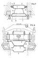
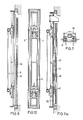
- FIGS. 11 and 11a show a further shield construction according to the invention.
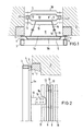
- the furnace chamber with the associated heating or chamber walls is indicated by 1.
- the coke oven door is, e.g. described in the German patent application P 33 27 337.5, consisting of a door body, with a power transmission unit and a sealing unit.
- the power transmission unit runs as a hollow profile along the door frame and is connected to the door frame at least via a locking device.
- the locking device is designed as a spring lock. These include locking hooks on the door frame 7 and pivotable locking bars on the door body, which act on the door body 7 via springs or power pistons.
- the sealing unit has a sealing plate 5, which is pressed against the door frame on the circumference of the door frame by means of many evenly distributed and spring-mounted screws 4.
- 5a denotes a cover that serves for insulation.
- the sealing plate 5 can be designed as a hollow profile, the hollow profile being filled with insulating compound 5b.
- the sealing plate can be provided with a one-sided bulge according to Figures 1 and 7 to the outside.
- angle irons are attached distributed over the height, of which angle irons 15 are screwed with screws 16 to further angle irons 14, which in turn are connected to a shaped profile 9 as an external protective shield.
- the connection between the shaped profile 9 and the angle iron 14 is made by hanging the shaped profile 9 with suitable hooks 9a on the angle iron 14.
- flanges or other profiles or screws can also be used.
- Another shape profile is attached to the shape profile 9 in mirror image as a protective shield by means of bolts 13 with spacers.
- FIGS. 1 and 2 the positions of the shaped profiles are shown at a greater distance from one another at 18, 19 in dashed form.
- Figures 4 and 5 the difference between the smaller and larger distance between the shaped profiles from each other is made clear.
- the shaped profiles of the inner protective shield 8 forming the wefts overlap, while the shaped profiles of the outer protective shield 9 abut one another with sufficient play for thermal expansion.
- the distance between the inner protective shield 8 and the sealing surface between the door body and the door frame 7 is 400 mm.
- the distance between the two protective shields is 120 mm. This corresponds to the usual stone plug depth.
- the ratio of the distance between the two protective shields 8 and 9 to the distance between the outer protective shield 9 and the sealing surface between the door body and the door frame 7 is between 1: 1 and 1: 1a, preferably between 1: 3 and 1 : 5.
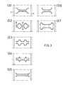
- FIG. 3 shows a number of possible cross sections for the shaped profiles.
- the shaped profiles can be rolled in one piece and / or folded and / or bent, or can be composed of several parts. The parts can be screwed or welded. In the simplest case, the shaped profiles are designed as smooth sheets.
- the cross sections according to FIG. 3 are advantageous. While according to FIG. 1, the shaped profiles are laterally connected to one another in cross section and have bulges in the middle between the connection points, the reverse is true according to FIG. 3.1.
- the shaped profiles according to FIG. 3.1 have a small distance in the middle and the shaped profiles are connected to one another via the bolts 13, while they are at a greater distance from the outside of the chamber walls.
- the protective shields then again run parallel to each other on the outside.
- the protective shields can also be curved in the form of a circular arc towards the chamber walls or angularly bent outwards according to FIG. 3.6.
- the ends are first curved outwards in the form of a circular arc and then again inwards in a semi-circular manner, so that the ends are directed towards one another.
- Figures 3.1 to 3.4 also contain various middle bulges, which are triangular, semicircular or trapezoid-like on the outside.
- All protective shields according to Figure 3 can be used together. I.e. e.g. combine the shaped profile 8 of FIG. 3.1 with the shaped profile 9 according to FIG. 3.2. This preferably serves to increase the section modulus of the shield construction.
- FIGS. 6 and 7 show additional sealing plates 24 which are provided with elongated holes 25.
- only one row of sealing plates is provided between the two shaped profiles 8 and 9.
- several rows of sealing plates can also be arranged one behind the other between the shaped profiles 8 and 9, or can be distributed over a plurality of shaped profiles arranged one behind the other.
- the sealing plates 24 are as close as possible to the outer molded profile 9 in order to hinder the gas entry into the outer raw gas channel between the molded profile 9 and the door body and to relieve the sealing member 6.
- FIG. 6 shows the raised state of the shaped profiles in the left half.
- the sealing plate 24 has settled from the chamber wall 2 in the raised state or has been pressed inwards and downwards by a plunger 26. It protrudes below the shape profile.
- the protective shields and sealing plates 24 stand on the furnace sole and the sealing plate 24 has leaned against the chamber wall 2.
- the sealing plate movement is up to 60 mm compared to the shaped profiles 8 and 9.
- the gap between the shaped profiles 8 and 9 and the chamber wall 2 is in the exemplary embodiment, depending on the width of the coke oven chamber, up to 20 mm in size. For example, a 15 mm gap is provided for an average chamber width of 45 cm.
- FIG. 7 also shows the S-shaped shape of the sealing plate 24, the sealing plates abutting the outer molded profile 9 on the inside and a vertical gap for the gas passage remaining between the molded profile 8 and the sealing plates.
- the various sealing plates 24 of the three shots of multi-part protective shields shown in FIG. 5a are optionally connected to one another via joints which, when the door is placed in the furnace chamber, transmit the upward movement of the lowest sealing plates 24 to the sealing plates arranged above them.
- Hinges with two hinge joints can serve as joints, which ensure power transmission in the vertical direction and allow freedom of movement in the horizontal longitudinal direction of the furnace chamber.
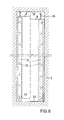
- the shield construction according to FIGS. 8 to 10 differs from the shield construction according to FIGS. 1 to 7 in that a further shield 40 is provided instead of the angle iron 14, 15.
- the shield 40 is screwed to the sealing plate 5 and the shields 8 and 9.
- a large number of screws are provided, which are distributed over the length of the door structure.
- One of the screws or a pair of screws arranged at the same height is firmly seated, the other screws can yield in the longitudinal slots of thermal expansion by displacement. The screws are loose for this, but are secured against complete loosening, for example with lock nuts.
- the shield 40 is in the same way as the shields 8 and 9 with that resulting from the distance of the shields 8 and 9 from the door body Dimension and the dimension resulting from the bulge of the sealing plate 5.
- the sealing plate 5 can also be regarded as a shield. All shields 5, 8, 9 and 40 can advantageously be made from sheet pile material.
- a shaped profile 50 with a larger bulge of 150 mm is provided instead of the sealing plate 5.
- a shield 41 is provided, the legs of which extend exactly to the edges of the shaped profile 50 which are produced by the bulging.
- the shield 41 is laterally provided with a plurality of slots 42.
Landscapes
- Chemical & Material Sciences (AREA)
- Engineering & Computer Science (AREA)
- Materials Engineering (AREA)
- Oil, Petroleum & Natural Gas (AREA)
- Organic Chemistry (AREA)
- Coke Industry (AREA)
Applications Claiming Priority (2)
| Application Number | Priority Date | Filing Date | Title |
|---|---|---|---|
| DE19853540845 DE3540845A1 (de) | 1985-11-18 | 1985-11-18 | Koksofentuer fuer einen horizontalkammer-verkokungsofen |
| DE3540845 | 1985-11-18 |
Publications (2)
| Publication Number | Publication Date |
|---|---|
| EP0223028A2 true EP0223028A2 (fr) | 1987-05-27 |
| EP0223028A3 EP0223028A3 (fr) | 1988-03-02 |
Family
ID=6286282
Family Applications (1)
| Application Number | Title | Priority Date | Filing Date |
|---|---|---|---|
| EP86113613A Withdrawn EP0223028A3 (fr) | 1985-11-18 | 1986-10-02 | Porte de four à coke à chambres horizontales |
Country Status (3)
| Country | Link |
|---|---|
| EP (1) | EP0223028A3 (fr) |
| JP (1) | JPS62119290A (fr) |
| DE (1) | DE3540845A1 (fr) |
Cited By (1)
| Publication number | Priority date | Publication date | Assignee | Title |
|---|---|---|---|---|
| EP0321640A1 (fr) * | 1987-12-19 | 1989-06-28 | Ruhrkohle Aktiengesellschaft | Porte de four à coke d'une construction avec écran |
Families Citing this family (1)
| Publication number | Priority date | Publication date | Assignee | Title |
|---|---|---|---|---|
| DE3743156A1 (de) * | 1987-08-03 | 1989-02-16 | Ruhrkohle Ag | Koksofentuer mit metallschild |
Family Cites Families (3)
| Publication number | Priority date | Publication date | Assignee | Title |
|---|---|---|---|---|
| US4086145A (en) * | 1977-03-14 | 1978-04-25 | Jones & Laughlin Steel Corporation | Coke oven door lining |
| EP0163773B1 (fr) * | 1984-01-05 | 1987-05-06 | Ruhrkohle Aktiengesellschaft | Porte de four à coke à chambres horizontales |
| DE3409224A1 (de) * | 1984-03-14 | 1985-09-19 | Carl Still Gmbh & Co Kg, 4350 Recklinghausen | Leichtbaustopfen fuer koksofentueren |
-
1985
- 1985-11-18 DE DE19853540845 patent/DE3540845A1/de not_active Ceased
-
1986
- 1986-10-02 EP EP86113613A patent/EP0223028A3/fr not_active Withdrawn
- 1986-11-13 JP JP26881386A patent/JPS62119290A/ja active Pending
Cited By (1)
| Publication number | Priority date | Publication date | Assignee | Title |
|---|---|---|---|---|
| EP0321640A1 (fr) * | 1987-12-19 | 1989-06-28 | Ruhrkohle Aktiengesellschaft | Porte de four à coke d'une construction avec écran |
Also Published As
| Publication number | Publication date |
|---|---|
| DE3540845A1 (de) | 1987-05-21 |
| JPS62119290A (ja) | 1987-05-30 |
| EP0223028A3 (fr) | 1988-03-02 |
Similar Documents
| Publication | Publication Date | Title |
|---|---|---|
| EP0028679A1 (fr) | Porte de four à coke ayant un espace collecteur de gaz de grand volume | |
| DE2948104C2 (de) | Elektrolysewanne | |
| DE3105703C2 (de) | Aus Schilden zusammengesetzte Verkokungsplatte | |
| EP0223028A2 (fr) | Porte de four à coke à chambres horizontales | |
| EP0163773B1 (fr) | Porte de four à coke à chambres horizontales | |
| DE3739452C1 (de) | Koksofentuer mit keramischem Schildaufbau | |
| DE3439860C2 (fr) | ||
| EP1124094A1 (fr) | Brique réfractaire et construction de paroi de four associée | |
| DE3440311C2 (fr) | ||
| DE3409224C2 (fr) | ||
| EP0058320B1 (fr) | Procédé de cokéfaction de charbon et four à coke pour la mise en oeuvre du procédé | |
| DE2908839C2 (de) | Vorrichtung zur Abdichtung der Kammern von Verkokungsöfen | |
| DE1526160C3 (de) | Wandkonstruktion für Feuerräume | |
| DD202304A5 (de) | Verfahren zum abdichten von horizontalkammerverkokungsoefen und koksofen mit koksofentueren | |
| DE3024514C2 (fr) | ||
| DE3440312C2 (fr) | ||
| DE2724982C3 (de) | Koksofenkammertürstopfen aus feuerfesten Steinen | |
| DE875340C (de) | Ofenkopfbewehrung mit gesondertem loesbarem Tuerrahmen | |
| DE3348043C2 (en) | Coke oven door with sheet pile | |
| EP0084366B1 (fr) | Porte pour chambre de four à coke | |
| EP0114183B1 (fr) | Porte pour four à coke à chambres horizontales | |
| DE681742C (de) | Koksofenbatterie zur Erzeugung von Gas und Koks | |
| DE3123249C2 (de) | Steckverbindung für schildförmige Verkokungsplatte | |
| EP0383813B1 (fr) | Bati de chambre | |
| DE935548C (de) | Schlackenkammerverschluss fuer Siemens-Martin-OEfen |
Legal Events
| Date | Code | Title | Description |
|---|---|---|---|
| PUAI | Public reference made under article 153(3) epc to a published international application that has entered the european phase |
Free format text: ORIGINAL CODE: 0009012 |
|
| AK | Designated contracting states |
Kind code of ref document: A2 Designated state(s): BE DE ES FR GB GR NL |
|
| PUAL | Search report despatched |
Free format text: ORIGINAL CODE: 0009013 |
|
| AK | Designated contracting states |
Kind code of ref document: A3 Designated state(s): BE DE ES FR GB GR NL |
|
| 17P | Request for examination filed |
Effective date: 19880120 |
|
| 17Q | First examination report despatched |
Effective date: 19890621 |
|
| STAA | Information on the status of an ep patent application or granted ep patent |
Free format text: STATUS: THE APPLICATION IS DEEMED TO BE WITHDRAWN |
|
| 18D | Application deemed to be withdrawn |
Effective date: 19900420 |
|
| RIN1 | Information on inventor provided before grant (corrected) |
Inventor name: BECKER, WOLFGANG, DR. |