EP0223030A1 - Dispositif de guidage d'une toupie portative adapté à un gabarit pour le fraisage des queues d'aronde - Google Patents
Dispositif de guidage d'une toupie portative adapté à un gabarit pour le fraisage des queues d'aronde Download PDFInfo
- Publication number
- EP0223030A1 EP0223030A1 EP86113644A EP86113644A EP0223030A1 EP 0223030 A1 EP0223030 A1 EP 0223030A1 EP 86113644 A EP86113644 A EP 86113644A EP 86113644 A EP86113644 A EP 86113644A EP 0223030 A1 EP0223030 A1 EP 0223030A1
- Authority
- EP
- European Patent Office
- Prior art keywords
- guide
- router
- guide plate
- shoe
- milling
- Prior art date
- Legal status (The legal status is an assumption and is not a legal conclusion. Google has not performed a legal analysis and makes no representation as to the accuracy of the status listed.)
- Granted
Links
- 238000003801 milling Methods 0.000 claims description 56
- 238000003780 insertion Methods 0.000 claims description 8
- 230000037431 insertion Effects 0.000 claims description 8
- 230000000149 penetrating effect Effects 0.000 claims description 2
- 238000006243 chemical reaction Methods 0.000 description 1
- 238000005553 drilling Methods 0.000 description 1
- 238000004519 manufacturing process Methods 0.000 description 1
- 238000005259 measurement Methods 0.000 description 1
- 238000000034 method Methods 0.000 description 1
- 230000000284 resting effect Effects 0.000 description 1
Images

Classifications
-
- B—PERFORMING OPERATIONS; TRANSPORTING
- B27—WORKING OR PRESERVING WOOD OR SIMILAR MATERIAL; NAILING OR STAPLING MACHINES IN GENERAL
- B27F—DOVETAILED WORK; TENONS; SLOTTING MACHINES FOR WOOD OR SIMILAR MATERIAL; NAILING OR STAPLING MACHINES
- B27F1/00—Dovetailed work; Tenons; Making tongues or grooves; Groove- and- tongue jointed work; Finger- joints
- B27F1/08—Making dovetails, tongues, or tenons, of definite limited length
- B27F1/12—Corner- locking mechanisms, i.e. machines for cutting crenellated joints
-
- B—PERFORMING OPERATIONS; TRANSPORTING
- B23—MACHINE TOOLS; METAL-WORKING NOT OTHERWISE PROVIDED FOR
- B23Q—DETAILS, COMPONENTS, OR ACCESSORIES FOR MACHINE TOOLS, e.g. ARRANGEMENTS FOR COPYING OR CONTROLLING; MACHINE TOOLS IN GENERAL CHARACTERISED BY THE CONSTRUCTION OF PARTICULAR DETAILS OR COMPONENTS; COMBINATIONS OR ASSOCIATIONS OF METAL-WORKING MACHINES, NOT DIRECTED TO A PARTICULAR RESULT
- B23Q9/00—Arrangements for supporting or guiding portable metal-working machines or apparatus
- B23Q9/0014—Portable machines provided with or cooperating with guide means supported directly by the workpiece during action
- B23Q9/0028—Portable machines provided with or cooperating with guide means supported directly by the workpiece during action the guide means being fixed only on the machine
Definitions
- the invention relates to a router guide for a grid-like tine milling jig, the router having a base plate provided with a central opening for the milling tool, which is adjustable in the milling machine axis direction and has fastening devices for a guide plate.
- Routers are known in a wide variety of designs. All common types have a high-speed drive motor and a base plate, which is attached to the motor via legs or the like and is adjustable relative to this in the milling axis direction.
- the base plate is with fasteners, for. B. thread holes, for a guide plate that is placed on the workpiece to be milled.
- Guide stops or the like can generally be attached to the guide plate for milling straight-line grooves or the like.
- a grid-like tine milling jig which has a table support plate and a back plate arranged at right angles thereto. Both panels are provided with a series of parallel longitudinal slots which merge into one another in the corner area of the two panels.
- comb-like wedge corner connections in particular dovetail wedge connections, can be produced, a hand drill being provided there as the drive device for the milling tool, a guide piece being clampable on the neck thereof.
- the guide piece is then guided exactly in the slots of the tine milling jig. Since the guide piece can only be attached to hand drills, the tine milling jig could not previously be used in connection with routers, so that key-edge connections with these devices could only be produced after very lengthy precision measurements and with a very precise setting of guide stops.
- the invention has for its object to provide a router operator, which can be used in conjunction with a grid-like tine milling jig for the convenient and quick production of wedge corner connections.
- the guide plate has on its underside a protruding, web-like guide shoe which is penetrated by the milling tool and which is directed radially to the passage opening for the milling tool.
- the guide plate and the guide shoe can be supplied to the user as a unit, which can easily be exchanged for the normal guide plate of a router.
- the already existing fastening devices on the base plate can be readily used; ie complex fixing elements for the guide shoe are not required.
- the router guide is particularly convenient to use because the milling tool is not only guided through the guide shoe, but also through the guide plate resting on the tine guide.
- the groove depth can be adjusted via an axial adjustment of the base plate. Since the router guide is adapted in its design to the usual accessories of a router, the clamping of the milling tool in the clamping head of the router is not hindered.
- the guide shoe can extend approximately to the edge of the guide plate and a lockable milling stroke limit stop can be slidably mounted on the guide shoe.
- the milling stroke limit stop which is integrated directly into the structure of the router guide due to its mounting on the guide shoe, allows the length of the grooves to be milled to be determined in a simple manner before the milling process begins.
- the guide shoe can have a T-shaped cross section at least in the area of the passage openings. A positive guidance of the milling tool in the guide slot of known tine milling gauges is thus achieved, with which a constantly constant groove depth is ensured.
- the guide shoe near the outer edge of the guide plate can have a threaded hole for a locking screw penetrating an elongated hole of the limit stop.
- the limit stop can be set continuously in different positions in this embodiment.
- the opposite of the stop, adjacent to the passage opening introducer of the guide shoe can have a length of about one to two times the diameter of the passage opening and be provided on the end face with insertion bevels which pass smoothly into the guide surfaces of the guide shoe.
- the guide shoe designed in this way only needs to be brought into a rough alignment with the respective guide slot of the tine milling jig, since the guide bevel and thus the milling tool are automatically centered as a result of the insertion bevels when the guide shoe is advanced further.
- the limit stop can be pushed as far as the passage opening and can have an axial stop for adjusting the milling tool.
- the limit stop can be provided in the region of its end face with a recess open towards the guide plate, the bottom surface of which forms the axial stop. The limit stop thus simultaneously functions as an axial alignment aid for the milling tool, which further simplifies the preparatory work for milling wedge connections.
- the limit stop on both ends can be provided with differently dimensioned adjustment recesses and can be implemented by 180 on the guide shoe.
- the router guide can be easily adapted to milling tools for producing different groove depths.
- the guide plate can be provided with a plurality of openings for fastening screws which are oversized, e.g. are designed as elongated holes, and the guide plate can be assigned a centering pin which can be clamped into the router, the centering of which fits into the passage opening without play.
- the router guide can be attached to different types of router. Thanks to the centering pin, the centering of the guide plate relative to the axis of the milling tool is achieved despite the oversize of the through holes.
- the guide plate can be assigned a plurality of guide shoes of different sizes, which can be exchangeably screwed onto the guide plate. Simple conversion measures make it possible to adapt to different tine milling gauges.
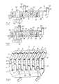
- the tine milling jig has a table support plate 3 and a back plate 4, each of which is provided with a series of parallel guide slots 5.
- the guide slots 5 merge into one another in the corner region of the plates 3, 4.
- comb-like wedge corner connections can be milled, the slots 5 serving as guides for a router 6.
- the various required work steps basically correspond to the way of working with a drilling machine. For this reason, a detailed explanation is dispensed with here and instead, reference is expressly made to the disclosure of DE-PS 26 42 924.
- the table platen 3 of the tine milling jig 2 is provided on its free edge with alignment fingers 7, as proposed in German patent application P 34 40 945.9, which further simplifies the procedure.
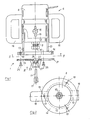
- the router 6 shown in more detail in FIGS. 1 and 2 consists of a drive motor 8, on the output shaft 9 of which a clamping head 10 for a milling tool 11 is provided.
- the housing of the motor 8 is enclosed on its lower part by a cylindrical sleeve 12, on which legs 13 are formed, which in turn carry an annular base plate 14.
- the sleeve 12 is provided with an elongated hole 15 which is penetrated by a clamping screw 16, as a result of which the sleeve 12 and thus also the base plate 14 can be moved continuously in the direction of the milling cutter axis 17 and locked in any position.
- the router 6 can be held and guided with the aid of handles 18.
- Fastening devices 19 in the form of screw holes for the router guide 1 are provided on the base plate 14 of the router 6; see. also Fig. 3.
- This essentially comprises a guide plate 21 and a web-like guide shoe 22 protruding from the underside and penetrated by the milling tool 11, on which a milling stroke limiting stop 23 is slidably mounted.
- the guide plate 21 has a plurality of openings 24 for fastening screws 25 for connection to the base plate 14 of the router 6.
- the openings 24 are designed as radial, stepped, elongated holes, so that the guide plate 21 can be fastened to a wide variety of router types.
- the guide plate 21 has in its center a passage opening 26 for the milling tool 11; see. Fig. 8.
- the guide shoe 22 also has a passage opening 27 for the milling tool 11, which is coaxial to the passage opening 26 of the guide plate 21.
- the guide shoe 22 is directed radially to the passage openings 26, 27 and extends to the edge 28 of the guide plate 21; see. FIGS. 3 and 6 to 8.
- the guide shoe 22 has a T-shaped cross section in the region of the passage opening 27 with lateral T webs 29 and, moreover, has a rectangular cross section. With the help of the T-webs 29, the guide shoe 22 can engage behind the tines 30, 31, which are formed between the slots 5 of the tine milling gauge 2.
- the tines 30, 31 are otherwise provided in the vicinity of the corner region of the plate 3, 4 with grooves 32 for the introduction of the T-webs 29.
- the guide shoe 22 has an introducer 33, which has a length of approximately one to two times the diameter of the passage opening 27 and is provided on the end face with insertion bevels 35.
- the insertion bevels 35 are achieved by a bow-shaped rounding of the insertion end 34, so that they merge into the lateral guide surfaces 36 of the guide shoe 22 without edges.
- the guide shoe 22 is interchangeably screwed to the guide plate 21 by means of countersunk screws 37, a centering pin 38 ensuring exact positioning; see. 7 and 8. In this way the guide shoe 22 is against another e.g. wider guide shoe 39 interchangeable (see FIG. 4), which is assigned a correspondingly larger tine milling gauge.
- the passage opening 26 of the guide plate 21 is larger than the passage opening 27 of the guide shoe 22 in order to also enable the router guide 1 to be adapted to the guide shoe 39 with an enlarged passage opening 40.
- the guide shoe 22 has near the outer edge 28 of the guide plate 21 a threaded bore 41 for a locking screw 42 which has an elongated hole 43 of the boundary through 23.
- the limit stop 23 is provided on its side facing the guide plate 21 with a rectangular groove 44 with which it engages around the rectangular area of the guide shoe 22 and is guided thereon. It carries a scale 45 on its lateral outer surface for setting the desired groove length.
- the limit stop 23 can be pushed up to the passage opening 27 of the guide shoe 22, which is why the rectangular groove 44 is widened in its end regions 46, 47 in order to accommodate the T-webs 29.
- the limit stop 22 is provided at its two stop ends 48, 49 each with a recess 50, 51 open towards the guide plate 21, the bottom surface of which forms an axial stop 52, 53 for adjusting the milling tool 11.
- Fig. 8 shows the adjustment by an axial stop 52 for relatively large groove depths.
- the router guide 1 is assigned a centering pin 54 which can be clamped into the clamping head 10 of the router 7 and whose centering 55 has no play in the passage opening 27 of the guide shoe 22 fits. After the thus achieved Centering the guide plate 21, the mounting screws 25 can then be fixed.
Landscapes
- Engineering & Computer Science (AREA)
- Mechanical Engineering (AREA)
- Life Sciences & Earth Sciences (AREA)
- Wood Science & Technology (AREA)
- Forests & Forestry (AREA)
- Milling, Drilling, And Turning Of Wood (AREA)
- Milling Processes (AREA)
- Pinball Game Machines (AREA)
- Impact Printers (AREA)
- Magnetic Heads (AREA)
Priority Applications (1)
| Application Number | Priority Date | Filing Date | Title |
|---|---|---|---|
| AT86113644T ATE51180T1 (de) | 1985-10-25 | 1986-10-02 | Oberfraesenfuehrer fuer eine gitterartige zinkenfraeslehre. |
Applications Claiming Priority (2)
| Application Number | Priority Date | Filing Date | Title |
|---|---|---|---|
| DE19853537992 DE3537992A1 (de) | 1985-10-25 | 1985-10-25 | Oberfraesenfuehrer fuer eine gitterartige zinkenfraeslehre |
| DE3537992 | 1985-10-25 |
Publications (2)
| Publication Number | Publication Date |
|---|---|
| EP0223030A1 true EP0223030A1 (fr) | 1987-05-27 |
| EP0223030B1 EP0223030B1 (fr) | 1990-03-21 |
Family
ID=6284445
Family Applications (1)
| Application Number | Title | Priority Date | Filing Date |
|---|---|---|---|
| EP86113644A Expired - Lifetime EP0223030B1 (fr) | 1985-10-25 | 1986-10-02 | Dispositif de guidage d'une toupie portative adapté à un gabarit pour le fraisage des queues d'aronde |
Country Status (3)
| Country | Link |
|---|---|
| EP (1) | EP0223030B1 (fr) |
| AT (1) | ATE51180T1 (fr) |
| DE (2) | DE3537992A1 (fr) |
Cited By (2)
| Publication number | Priority date | Publication date | Assignee | Title |
|---|---|---|---|---|
| EP0320869A3 (fr) * | 1987-12-17 | 1991-05-15 | Werkzeug-Gesellschaft mit beschränkter Haftung | Dispositif auxiliaire pour fraiser les queues-d'aronde |
| US9988906B2 (en) | 2013-02-08 | 2018-06-05 | General Electric Company | Turbomachine rotor blade milling machine system and method of field repairing a turbomachine rotor blade |
Families Citing this family (2)
| Publication number | Priority date | Publication date | Assignee | Title |
|---|---|---|---|---|
| US6027289A (en) * | 1995-04-19 | 2000-02-22 | Posh; Ransom | Lateral movement router guide |
| US5772368A (en) * | 1995-04-19 | 1998-06-30 | Posh; Ransom D. | Full-size router tilt base |
Citations (9)
| Publication number | Priority date | Publication date | Assignee | Title |
|---|---|---|---|---|
| US1462962A (en) * | 1922-04-10 | 1923-07-24 | Theodore C Hansen | Routing machine |
| US2662562A (en) * | 1949-12-27 | 1953-12-15 | Carl G Lindell | Saw attachment for electric hand drills |
| GB818518A (en) * | 1953-07-25 | 1959-08-19 | Bosch Gmbh Robert | Improvements in or relating to a device for hand-operated machine tools for carryingout comb-jointing and like operations |
| US2970618A (en) * | 1956-12-31 | 1961-02-07 | William L Mitchell | Guide means for hand routers |
| US3346026A (en) * | 1965-07-12 | 1967-10-10 | Pluchino Anthony | Router guide attachment |
| CH590117A5 (en) * | 1976-05-28 | 1977-07-29 | Kobler Zuercher Albert | Machining system using portable electric tool - has tool support working in guide rail clamped to workpiece and fitted with distance stops |
| FR2350936A1 (fr) * | 1976-05-15 | 1977-12-09 | Wolff Robert | Gabarit |
| US4197887A (en) * | 1959-09-22 | 1980-04-15 | Groves Gerald T | Router guide assembly |
| EP0126285A1 (fr) * | 1983-05-24 | 1984-11-28 | Eugen Lutz + Co. | Rabot électrique à main |
-
1985
- 1985-10-25 DE DE19853537992 patent/DE3537992A1/de not_active Withdrawn
-
1986
- 1986-10-02 DE DE8686113644T patent/DE3669681D1/de not_active Expired - Fee Related
- 1986-10-02 AT AT86113644T patent/ATE51180T1/de active
- 1986-10-02 EP EP86113644A patent/EP0223030B1/fr not_active Expired - Lifetime
Patent Citations (9)
| Publication number | Priority date | Publication date | Assignee | Title |
|---|---|---|---|---|
| US1462962A (en) * | 1922-04-10 | 1923-07-24 | Theodore C Hansen | Routing machine |
| US2662562A (en) * | 1949-12-27 | 1953-12-15 | Carl G Lindell | Saw attachment for electric hand drills |
| GB818518A (en) * | 1953-07-25 | 1959-08-19 | Bosch Gmbh Robert | Improvements in or relating to a device for hand-operated machine tools for carryingout comb-jointing and like operations |
| US2970618A (en) * | 1956-12-31 | 1961-02-07 | William L Mitchell | Guide means for hand routers |
| US4197887A (en) * | 1959-09-22 | 1980-04-15 | Groves Gerald T | Router guide assembly |
| US3346026A (en) * | 1965-07-12 | 1967-10-10 | Pluchino Anthony | Router guide attachment |
| FR2350936A1 (fr) * | 1976-05-15 | 1977-12-09 | Wolff Robert | Gabarit |
| CH590117A5 (en) * | 1976-05-28 | 1977-07-29 | Kobler Zuercher Albert | Machining system using portable electric tool - has tool support working in guide rail clamped to workpiece and fitted with distance stops |
| EP0126285A1 (fr) * | 1983-05-24 | 1984-11-28 | Eugen Lutz + Co. | Rabot électrique à main |
Cited By (2)
| Publication number | Priority date | Publication date | Assignee | Title |
|---|---|---|---|---|
| EP0320869A3 (fr) * | 1987-12-17 | 1991-05-15 | Werkzeug-Gesellschaft mit beschränkter Haftung | Dispositif auxiliaire pour fraiser les queues-d'aronde |
| US9988906B2 (en) | 2013-02-08 | 2018-06-05 | General Electric Company | Turbomachine rotor blade milling machine system and method of field repairing a turbomachine rotor blade |
Also Published As
| Publication number | Publication date |
|---|---|
| DE3537992A1 (de) | 1987-05-07 |
| DE3669681D1 (de) | 1990-04-26 |
| ATE51180T1 (de) | 1990-04-15 |
| EP0223030B1 (fr) | 1990-03-21 |
Similar Documents
| Publication | Publication Date | Title |
|---|---|---|
| EP0144490A2 (fr) | Dispositif de guidage de foreuse ou fraise pour machines échangeables d'entraînement | |
| EP0558692B1 (fr) | Dispositif de protection et de guidage pour fraiseuses a bois--- | |
| DE3046922C2 (de) | Druckluft-Handbohrmaschine | |
| DE4203721C2 (de) | Radiusfräsvorrichtung, insbesondere zum Fräsen von kreisbogenförmigen Nuten in Holz | |
| DE3430496C2 (de) | Hilfsvorrichtung zum Fräsen von Schwalbenschwanznuten bei rechtwinklig zusammenzuzinkenden Brettern | |
| DE3622638C2 (fr) | ||
| DE2941179B1 (de) | Zer?kzeug | |
| DE2719447A1 (de) | Spannvorrichtung | |
| EP0223030B1 (fr) | Dispositif de guidage d'une toupie portative adapté à un gabarit pour le fraisage des queues d'aronde | |
| EP0050210A2 (fr) | Gabarit de perçage | |
| EP0263476A2 (fr) | Procédé d'alignement d'une palette sur une table d'une machine-outil et pièce d'alignement à cet effet | |
| DE3901556A1 (de) | Fuehrungsvorrichtung | |
| DE3333169C2 (fr) | ||
| EP0172555B1 (fr) | Vice | |
| EP0004312B1 (fr) | Tête de rabotage à lames réversibles et interchangeables | |
| DE2328439C3 (de) | Schwenkbarer Werkstück-Aufspanntisch für Werkzeugmaschinen, insbesondere für Universal-Fräsmaschinen | |
| DE3215957A1 (de) | Bohrlehre zum fuehren eines werkzeuges/bohrers | |
| DE2225136A1 (de) | Verbesserungen an Werkstück-Spannvorrichtungen | |
| EP0413203A2 (fr) | Dispositif de perçage | |
| DE102024002708B3 (de) | Vorrichtung zum Führen von Werkzeugen auf einem Werkstück parallel zu einer Werkstückkante | |
| DE3424680A1 (de) | Verfahren und vorrichtung zum fraesen und nuten von rahmenteilen aus holz | |
| DE202004000359U1 (de) | Hilfsvorrichtung zum Bearbeiten eines Werkstückes | |
| DE4305954A1 (de) | Vorrichtung zum Bearbeiten von plattenförmigen Werkstücken | |
| DE9211151U1 (de) | Radiusfräsvorrichtung, insbesondere zum Fräsen von kreisbogenförmigen Nuten in Holz | |
| DE3916758A1 (de) | Bohrkopf mit einstellbarer schneide |
Legal Events
| Date | Code | Title | Description |
|---|---|---|---|
| PUAI | Public reference made under article 153(3) epc to a published international application that has entered the european phase |
Free format text: ORIGINAL CODE: 0009012 |
|
| AK | Designated contracting states |
Kind code of ref document: A1 Designated state(s): AT BE CH DE ES FR GB IT LI NL SE |
|
| 17P | Request for examination filed |
Effective date: 19871030 |
|
| 17Q | First examination report despatched |
Effective date: 19881213 |
|
| DIN1 | Information on inventor provided before grant (deleted) | ||
| RAP1 | Party data changed (applicant data changed or rights of an application transferred) |
Owner name: WERKZEUG-GESELLSCHAFT MIT BESCHRAENKTER HAFTUNG |
|
| RIN1 | Information on inventor provided before grant (corrected) |
Inventor name: WOLFF, ROBERT |
|
| GRAA | (expected) grant |
Free format text: ORIGINAL CODE: 0009210 |
|
| AK | Designated contracting states |
Kind code of ref document: B1 Designated state(s): AT BE CH DE ES FR GB IT LI NL SE |
|
| PG25 | Lapsed in a contracting state [announced via postgrant information from national office to epo] |
Ref country code: IT Free format text: LAPSE BECAUSE OF FAILURE TO SUBMIT A TRANSLATION OF THE DESCRIPTION OR TO PAY THE FEE WITHIN THE PRE;WARNING: LAPSES OF ITALIAN PATENTS WITH EFFECTIVE DATE BEFORE 2007 MAY HAVE OCCURRED AT ANY TIME BEFORE 2007. THE CORRECT EFFECTIVE DATE MAY BE DIFFERENT FROM THE ONE RECORDED.SCRIBED TIME-LIMIT Effective date: 19900321 Ref country code: SE Effective date: 19900321 Ref country code: NL Effective date: 19900321 Ref country code: FR Effective date: 19900321 Ref country code: GB Effective date: 19900321 Ref country code: BE Effective date: 19900321 |
|
| REF | Corresponds to: |
Ref document number: 51180 Country of ref document: AT Date of ref document: 19900415 Kind code of ref document: T |
|
| REF | Corresponds to: |
Ref document number: 3669681 Country of ref document: DE Date of ref document: 19900426 |
|
| PG25 | Lapsed in a contracting state [announced via postgrant information from national office to epo] |
Ref country code: ES Free format text: LAPSE BECAUSE OF FAILURE TO SUBMIT A TRANSLATION OF THE DESCRIPTION OR TO PAY THE FEE WITHIN THE PRESCRIBED TIME-LIMIT Effective date: 19900702 |
|
| EN | Fr: translation not filed | ||
| NLV1 | Nl: lapsed or annulled due to failure to fulfill the requirements of art. 29p and 29m of the patents act | ||
| GBV | Gb: ep patent (uk) treated as always having been void in accordance with gb section 77(7)/1977 [no translation filed] | ||
| PG25 | Lapsed in a contracting state [announced via postgrant information from national office to epo] |
Ref country code: AT Effective date: 19901002 |
|
| PG25 | Lapsed in a contracting state [announced via postgrant information from national office to epo] |
Ref country code: CH Effective date: 19901031 Ref country code: LI Effective date: 19901031 |
|
| PLBE | No opposition filed within time limit |
Free format text: ORIGINAL CODE: 0009261 |
|
| STAA | Information on the status of an ep patent application or granted ep patent |
Free format text: STATUS: NO OPPOSITION FILED WITHIN TIME LIMIT |
|
| 26N | No opposition filed | ||
| REG | Reference to a national code |
Ref country code: CH Ref legal event code: PL |
|
| PGFP | Annual fee paid to national office [announced via postgrant information from national office to epo] |
Ref country code: DE Payment date: 19921005 Year of fee payment: 7 |
|
| PG25 | Lapsed in a contracting state [announced via postgrant information from national office to epo] |
Ref country code: DE Effective date: 19940701 |