EP0223038A1 - Tête de sondage pour examen ultrasonique - Google Patents
Tête de sondage pour examen ultrasonique Download PDFInfo
- Publication number
- EP0223038A1 EP0223038A1 EP86113804A EP86113804A EP0223038A1 EP 0223038 A1 EP0223038 A1 EP 0223038A1 EP 86113804 A EP86113804 A EP 86113804A EP 86113804 A EP86113804 A EP 86113804A EP 0223038 A1 EP0223038 A1 EP 0223038A1
- Authority
- EP
- European Patent Office
- Prior art keywords
- test head
- receiver
- transmitter
- segments
- oscillator
- Prior art date
- Legal status (The legal status is an assumption and is not a legal conclusion. Google has not performed a legal analysis and makes no representation as to the accuracy of the status listed.)
- Granted
Links
- 238000005516 engineering process Methods 0.000 claims abstract description 5
- 238000012360 testing method Methods 0.000 claims description 44
- 230000005855 radiation Effects 0.000 claims description 3
- 230000001154 acute effect Effects 0.000 claims description 2
- 239000000523 sample Substances 0.000 claims description 2
- 239000000969 carrier Substances 0.000 abstract description 4
- 230000035945 sensitivity Effects 0.000 description 9
- 230000005284 excitation Effects 0.000 description 4
- 239000007799 cork Substances 0.000 description 2
- 239000002184 metal Substances 0.000 description 2
- 241001136792 Alle Species 0.000 description 1
- 230000008878 coupling Effects 0.000 description 1
- 238000010168 coupling process Methods 0.000 description 1
- 238000005859 coupling reaction Methods 0.000 description 1
- 238000013016 damping Methods 0.000 description 1
- 238000010586 diagram Methods 0.000 description 1
- 230000003760 hair shine Effects 0.000 description 1
- 239000007788 liquid Substances 0.000 description 1
- 239000000463 material Substances 0.000 description 1
- 238000000034 method Methods 0.000 description 1
- 229920000058 polyacrylate Polymers 0.000 description 1
- 238000000926 separation method Methods 0.000 description 1
- 229910001220 stainless steel Inorganic materials 0.000 description 1
- 239000010935 stainless steel Substances 0.000 description 1
- 230000009897 systematic effect Effects 0.000 description 1
- 238000004154 testing of material Methods 0.000 description 1
- 238000002604 ultrasonography Methods 0.000 description 1
Images


Classifications
-
- B—PERFORMING OPERATIONS; TRANSPORTING
- B06—GENERATING OR TRANSMITTING MECHANICAL VIBRATIONS IN GENERAL
- B06B—METHODS OR APPARATUS FOR GENERATING OR TRANSMITTING MECHANICAL VIBRATIONS OF INFRASONIC, SONIC, OR ULTRASONIC FREQUENCY, e.g. FOR PERFORMING MECHANICAL WORK IN GENERAL
- B06B1/00—Methods or apparatus for generating mechanical vibrations of infrasonic, sonic, or ultrasonic frequency
- B06B1/02—Methods or apparatus for generating mechanical vibrations of infrasonic, sonic, or ultrasonic frequency making use of electrical energy
- B06B1/06—Methods or apparatus for generating mechanical vibrations of infrasonic, sonic, or ultrasonic frequency making use of electrical energy operating with piezoelectric effect or with electrostriction
- B06B1/0607—Methods or apparatus for generating mechanical vibrations of infrasonic, sonic, or ultrasonic frequency making use of electrical energy operating with piezoelectric effect or with electrostriction using multiple elements
- B06B1/0622—Methods or apparatus for generating mechanical vibrations of infrasonic, sonic, or ultrasonic frequency making use of electrical energy operating with piezoelectric effect or with electrostriction using multiple elements on one surface
Definitions
- the invention relates to a test head for ultrasonic testing in ⁇ technology with a transmitter and a receiver, each comprising a piezoelectric vibrator on a vibrating support, the transmitter and receiver being structurally combined so that their radiation directions are at least approximately at right angles to a test specimen surface and under a point Angles to it.
- the invention is based on the task of simplifying work with the ⁇ technology. In other words, the above-mentioned inconvenience should be remedied.
- the transducer carrier of the transmitter or of the receiver has a plurality of transducer segments which can be individually controlled via switching elements, and that the transducer carriers are enclosed in a common housing.
- the invention thus combines in a stable housing which is suitable for easy handling: 1.
- a vertical test head which can also have an inclination of up to 20 ° and is preferably used as a transmitter, and 2.
- an angle test head which is equipped with several segmented transducers and is preferably used as a receiver.
- the vertical test head part with a large-area transducer delivers an intensive sound field with a high excitation amplitude or sensitivity directly below the test head.
- the more strip-shaped transducers of the angle test head part simultaneously generate a quite divergent sound field for a wide sensitivity or excitation depth zone.
- the segmented oscillators of the angle test head can be activated separately or together by switching elements, preferably by switches, which are located on the test head housing. This allows the sensitivity range of the test head to be varied. One thus obtains a test head for several depth zones, which largely eliminates the tediousness mentioned in the book mentioned, since the new test head no longer needs to be moved to adjust the depth.
- the oscillator segments can be applied in a simple manner to a usually wedge-shaped oscillator carrier, so that they have the same radiation angle with respect to the vertical test head part.
- different insonification angles can also be used, so that greater depths can be achieved even with a relatively small test head, as will be described in more detail later.
- all elements can be provided with the same lead distance in order to influence the runtime dynamics of the test head. This is done in a known manner by a step-like design of the vibrating support.
- the common housing gives the test head according to the invention a stable design, so that the sensitive transducers are well protected.
- the common housing can also accommodate the switches for the oscillator segments and can have side sockets for connecting measuring lines.
- the test head shown schematically in FIG. 1, in particular without a housing, comprises a vertical test head part 1, which is also referred to as a zero degree transducer, and an angle test head part 2.
- the vertical test head part 1 comprises a vibrating support 4 and a piezoelectric vibrator 5.
- the angular test head part 2 has a wedge-shaped part Schwingerlini 7 with a segmented into four parts 8, 9, 10 and 11 Schwinger 12. Between the Test head parts 1 and 2, a layer of damping material 14 is provided, which serves the acoustic separation between the transmitter and receiver.
- the vertical test head part 1 delivers a longitudinal wave sound beam, the central beam 15 of which runs at right angles to the surface of the test specimen, not shown.
- the longitudinal or transverse sound bundles resulting from the oscillator segments 8 to 11 intersect with the sound bundle of the vertical test head part 1, so that central beam paths according to 18, 19, 20 and 21 are set.
- the transmitted beam strikes flat reflectors, such as those represented by crack tips, binding errors, etc., cylinder waves are excited, which are then selectively received with the receiver segments depending on the depth of the reflector.
- the central beam 15 can also run somewhat inclined, namely to such an extent (up to 20 °) that the weld seam is not passed through.
- Central beam 15 and beam paths 18 to 21 are inclined to the same side.
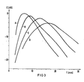
- the depth focusing listed in Table 2 can be carried out.
- the eight focus areas designated there with the capital letters A to H are obtained by making the four oscillator segments 8 to 11 effective according to the table.
- the effectiveness is represented by a cross, the ineffectiveness by a circle.
- the focus curves shown in FIGS. 3 and 4 result depending on the segment excitation.
- the diagrams show the reflector depth position T in millimeters on the abscissa and the specific sensitivity E in dB on the ordinate, the sensitivity for the curves B to H being related to the sensitivity of the focus area A.
- the new test head enables systematic focusing that increases the depth sensitivity range of the test head.
- the test head shown in Figure 5 has a special feature that the vibrating support 7 'in the area of the vibrator 12' forms a step-shaped surface. Therefore, the vibrating segments 8 'to 11' are offset from each other. They have the same insonification angles and their lead lengths 25 given by the oscillator body 7 'are of the same length.
- the surface 26 of the vibrating body 7 "carrying the vibrator 12" is curved upwards in steps.
- the central beam paths 18 "to 21" have therefore e.g. every 5 ° between 30 ° and 45 ° diverging insonification angles. This has the consequence that the "interfaces" with the beam 15 "are pulled further apart.
- test head shows that the plastic, e.g. Polyacrylate, existing transducer carriers 4 and 7 are glued to one another via a 2 mm thick cork plate 14, which projects beyond the 8 mm height of the transducer carriers.
- parts 4, 7 and 14 form the flat underside in a metal housing 30, the inside 31 of which is provided with a 1 mm thick cork lining 32.
- the housing 30 is made of 1.5 mm thick stainless steel and has a rectangular shape. The depth, which cannot be seen from the figure, is approximately half the width of the housing, which is 30 mm.
- a fourfold on-off switch 35 is attached to the metal housing 30, the contacts 36 of which are actuated individually via buttons 37 that come from the top of the housing 30 protrude.
- two sockets 39 and 40 are seated in the wall of the housing 30. Socket 39 is connected to the oscillator 5 of the vertical test head part 1.
- the oscillating segments 8 to 11 of the angle test head part 2 are guided via the switch 35 to the socket 40, so that the segments 8 to 11 can be made effective individually or in combination.
Landscapes
- Engineering & Computer Science (AREA)
- Mechanical Engineering (AREA)
- Investigating Or Analyzing Materials By The Use Of Ultrasonic Waves (AREA)
Applications Claiming Priority (2)
| Application Number | Priority Date | Filing Date | Title |
|---|---|---|---|
| DE3537062 | 1985-10-17 | ||
| DE3537062 | 1985-10-17 |
Publications (2)
| Publication Number | Publication Date |
|---|---|
| EP0223038A1 true EP0223038A1 (fr) | 1987-05-27 |
| EP0223038B1 EP0223038B1 (fr) | 1991-01-02 |
Family
ID=6283826
Family Applications (1)
| Application Number | Title | Priority Date | Filing Date |
|---|---|---|---|
| EP86113804A Expired - Lifetime EP0223038B1 (fr) | 1985-10-17 | 1986-10-06 | Tête de sondage pour examen ultrasonique |
Country Status (2)
| Country | Link |
|---|---|
| EP (1) | EP0223038B1 (fr) |
| DE (1) | DE3676448D1 (fr) |
Citations (3)
| Publication number | Priority date | Publication date | Assignee | Title |
|---|---|---|---|---|
| CA1118882A (fr) * | 1979-05-07 | 1982-02-23 | Jiri Vrba | Sonde aux ultrasons |
| DE3048188A1 (de) * | 1980-12-19 | 1982-07-29 | Siemens AG, 1000 Berlin und 8000 München | "ultraschallpruefkopf" |
| DE2931609C2 (de) * | 1978-08-04 | 1985-04-11 | Röntgen Technische Dienst B.V., Rotterdam | Einrichtung zur Untersuchung metallischer Körper mittels Ultraschall |
-
1986
- 1986-10-06 DE DE8686113804T patent/DE3676448D1/de not_active Expired - Lifetime
- 1986-10-06 EP EP86113804A patent/EP0223038B1/fr not_active Expired - Lifetime
Patent Citations (3)
| Publication number | Priority date | Publication date | Assignee | Title |
|---|---|---|---|---|
| DE2931609C2 (de) * | 1978-08-04 | 1985-04-11 | Röntgen Technische Dienst B.V., Rotterdam | Einrichtung zur Untersuchung metallischer Körper mittels Ultraschall |
| CA1118882A (fr) * | 1979-05-07 | 1982-02-23 | Jiri Vrba | Sonde aux ultrasons |
| DE3048188A1 (de) * | 1980-12-19 | 1982-07-29 | Siemens AG, 1000 Berlin und 8000 München | "ultraschallpruefkopf" |
Non-Patent Citations (1)
| Title |
|---|
| PRODUCT ENGINEERING, Band 41, Nr. 8, 13. April 1970, Seiten 46,47, New York, US; M. REID: "Ultrasonic flaw detection could have averted F-111 crash" * |
Also Published As
| Publication number | Publication date |
|---|---|
| EP0223038B1 (fr) | 1991-01-02 |
| DE3676448D1 (de) | 1991-02-07 |
Similar Documents
| Publication | Publication Date | Title |
|---|---|---|
| EP0383972B1 (fr) | Transducteur ultrasonore à éléments de vibration trapézoidaux, et procédé et dispositif pour leur fabrication | |
| DE3147482C1 (de) | Ultraschallpruefkopf mit einer Vielzahl von Ultraschallwandlern | |
| DE2260932C3 (de) | Verfahren zum Bestimmen der RiBtiefe von in Werkstücken auftretenden Rissen | |
| DE3526488A1 (de) | Ultraschall-wandler mit piezoelektrischem verbundmaterial | |
| DE3724629A1 (de) | Piezoelektrisch anregbares resonanzsystem | |
| EP0308899A2 (fr) | Transducteur à ultrasons avec une caractéristique d'émission et réception astigmatique | |
| DE69120905T2 (de) | Akustisches Mikroskopsystem | |
| DE3225586A1 (de) | Ultraschall-mikroskop | |
| DE102019106427B4 (de) | Wandler und Wandleranordnung für Ultraschall-Prüfkopfsysteme, Ultraschall-Prüfkopfsystem und Prüfverfahren | |
| DE3643575A1 (de) | Laserinduzierte schallerzeugung fuer ein schallmodul | |
| DE3121993A1 (de) | Ultraschall-abtastgeraet | |
| DE4406818C1 (de) | Verfahren und Vorrichtung zum Verschweißen von zumindest Metallteilen | |
| EP0223038B1 (fr) | Tête de sondage pour examen ultrasonique | |
| DE3241814C2 (de) | Ultraschallmikroskop | |
| EP1206698B1 (fr) | Systeme de detection par ultrasons | |
| EP1087229B1 (fr) | Méthode et appareil pour la détection des défauts par ultrasons | |
| DE8529564U1 (de) | Prüfkopf zur Ultraschallprüfung | |
| WO2002061413A2 (fr) | Capteur ultrasonique pour la commande de processus pour le soudage par resistance par points | |
| DE102005037725B4 (de) | Luftfeder mit Ultraschall-Höhenmesseinrichtung | |
| DE2632323C3 (de) | Vorrichtung zur Ultraschallprüfung von plattenförmigen Körpern, insbesondere Blechband, nach dem Impuls-Echo-Verfahren mit Lambwellen | |
| DE3715914A1 (de) | Verfahren und vorrichtung zum nachweis von rissen mit hilfe von ultraschall | |
| WO2006076998A2 (fr) | Dispositif pour determiner et/ou surveiller un debit volumique et/ou massique | |
| DE60100410T2 (de) | Methode zur Messung der Festigkeit einer geschweissten Anordnung sowie hierauf beruhende Geräte zur Messung der Geschwindigkeit von Ultraschall-Oberflächenwellen | |
| EP0425765A1 (fr) | Procédé de détection des fissures par ultrasons | |
| EP1148335A1 (fr) | Dispositif de contrôle par ultrasons |
Legal Events
| Date | Code | Title | Description |
|---|---|---|---|
| PUAI | Public reference made under article 153(3) epc to a published international application that has entered the european phase |
Free format text: ORIGINAL CODE: 0009012 |
|
| AK | Designated contracting states |
Kind code of ref document: A1 Designated state(s): DE NL |
|
| 17P | Request for examination filed |
Effective date: 19870708 |
|
| RAP1 | Party data changed (applicant data changed or rights of an application transferred) |
Owner name: SIEMENS AKTIENGESELLSCHAFT |
|
| 17Q | First examination report despatched |
Effective date: 19890403 |
|
| GRAA | (expected) grant |
Free format text: ORIGINAL CODE: 0009210 |
|
| AK | Designated contracting states |
Kind code of ref document: B1 Designated state(s): DE NL |
|
| REF | Corresponds to: |
Ref document number: 3676448 Country of ref document: DE Date of ref document: 19910207 |
|
| PLBE | No opposition filed within time limit |
Free format text: ORIGINAL CODE: 0009261 |
|
| STAA | Information on the status of an ep patent application or granted ep patent |
Free format text: STATUS: NO OPPOSITION FILED WITHIN TIME LIMIT |
|
| 26N | No opposition filed | ||
| PGFP | Annual fee paid to national office [announced via postgrant information from national office to epo] |
Ref country code: NL Payment date: 19931031 Year of fee payment: 8 |
|
| PG25 | Lapsed in a contracting state [announced via postgrant information from national office to epo] |
Ref country code: NL Effective date: 19950501 |
|
| NLV4 | Nl: lapsed or anulled due to non-payment of the annual fee | ||
| PGFP | Annual fee paid to national office [announced via postgrant information from national office to epo] |
Ref country code: DE Payment date: 19961216 Year of fee payment: 11 |
|
| PG25 | Lapsed in a contracting state [announced via postgrant information from national office to epo] |
Ref country code: DE Free format text: LAPSE BECAUSE OF NON-PAYMENT OF DUE FEES Effective date: 19980701 |