EP0223051B1 - Sicherheitsbelüftung gegen Überfüllung für Kraftstoff-Behälter - Google Patents
Sicherheitsbelüftung gegen Überfüllung für Kraftstoff-Behälter Download PDFInfo
- Publication number
- EP0223051B1 EP0223051B1 EP19860114072 EP86114072A EP0223051B1 EP 0223051 B1 EP0223051 B1 EP 0223051B1 EP 19860114072 EP19860114072 EP 19860114072 EP 86114072 A EP86114072 A EP 86114072A EP 0223051 B1 EP0223051 B1 EP 0223051B1
- Authority
- EP
- European Patent Office
- Prior art keywords
- flap
- valve
- shut
- spring
- connecting piece
- Prior art date
- Legal status (The legal status is an assumption and is not a legal conclusion. Google has not performed a legal analysis and makes no representation as to the accuracy of the status listed.)
- Expired
Links
- 239000002828 fuel tank Substances 0.000 title claims description 9
- 238000013022 venting Methods 0.000 title claims 4
- 239000000446 fuel Substances 0.000 claims description 4
- 238000007789 sealing Methods 0.000 claims description 4
- 230000005484 gravity Effects 0.000 claims description 3
- 238000003780 insertion Methods 0.000 claims description 3
- 230000037431 insertion Effects 0.000 claims description 3
- 239000000945 filler Substances 0.000 description 5
- 238000009423 ventilation Methods 0.000 description 3
- 230000000903 blocking effect Effects 0.000 description 1
- 238000005429 filling process Methods 0.000 description 1
- 230000007257 malfunction Effects 0.000 description 1
- 230000000717 retained effect Effects 0.000 description 1
- 230000000630 rising effect Effects 0.000 description 1
Images

Classifications
-
- B—PERFORMING OPERATIONS; TRANSPORTING
- B60—VEHICLES IN GENERAL
- B60K—ARRANGEMENT OR MOUNTING OF PROPULSION UNITS OR OF TRANSMISSIONS IN VEHICLES; ARRANGEMENT OR MOUNTING OF PLURAL DIVERSE PRIME-MOVERS IN VEHICLES; AUXILIARY DRIVES FOR VEHICLES; INSTRUMENTATION OR DASHBOARDS FOR VEHICLES; ARRANGEMENTS IN CONNECTION WITH COOLING, AIR INTAKE, GAS EXHAUST OR FUEL SUPPLY OF PROPULSION UNITS IN VEHICLES
- B60K15/00—Arrangement in connection with fuel supply of combustion engines or other fuel consuming energy converters, e.g. fuel cells; Mounting or construction of fuel tanks
- B60K15/03—Fuel tanks
- B60K15/04—Tank inlets
-
- B—PERFORMING OPERATIONS; TRANSPORTING
- B60—VEHICLES IN GENERAL
- B60K—ARRANGEMENT OR MOUNTING OF PROPULSION UNITS OR OF TRANSMISSIONS IN VEHICLES; ARRANGEMENT OR MOUNTING OF PLURAL DIVERSE PRIME-MOVERS IN VEHICLES; AUXILIARY DRIVES FOR VEHICLES; INSTRUMENTATION OR DASHBOARDS FOR VEHICLES; ARRANGEMENTS IN CONNECTION WITH COOLING, AIR INTAKE, GAS EXHAUST OR FUEL SUPPLY OF PROPULSION UNITS IN VEHICLES
- B60K15/00—Arrangement in connection with fuel supply of combustion engines or other fuel consuming energy converters, e.g. fuel cells; Mounting or construction of fuel tanks
- B60K15/03—Fuel tanks
- B60K15/035—Fuel tanks characterised by venting means
- B60K15/03519—Valve arrangements in the vent line
Definitions
- the invention relates to a safety ventilation device against overfilling for fuel tanks in motor vehicles, in which the tank communicates with the atmosphere during non-filling via a nozzle which opens into the tank and an air pocket located therein, which causes the fuel to rise in prevents this nozzle, and which includes a shut-off valve for said nozzle.
- shut-off valve for the connection piece which is intended to prevent overfilling of the container
- the closure lid of the container or a closing flap actuated by the closure lid of the container or a closing flap.
- the aim of the invention is therefore to close the shut-off valve for the connection of the container to the open air by simple and safe means during filling.
- valve mentioned is closed by inserting the nozzle into the filler neck of the fuel tank. Said valve is actuated by inserting the fuel nozzle into the neck of the fuel tank filler neck.
- the arrangement according to the invention is completely housed in the container, which considerably simplifies the execution.
- the shut-off valve is no longer actuated and the container is automatically and safely reconnected to the air.
- the shut-off valve is preferably actuated by a flap which is firmly connected in rotation to a shut-off and sealing flap of the container.
- the actuating flap of the shut-off and sealing flap is advantageously articulated on the axis of rotation of the latter and is displaced by a spring up to a stop position. 4th
- the shut-off valve comprises a flap which is pressed against a seat by a spring and has a plunger on which the nozzle acts
- the device is characterized in that a cage is provided with a seal which cooperates with a seat of the ventilation spigot, is slidably arranged on said flap and contains a ball seated by gravity on inclined planes of the flap
- the ball When the vehicle is standing upright, the ball is supported by gravity on the slide cage and removes the seal it carries from the seat of the seal neck, which thereby opens. If the vehicle tips over, the ball slides against one or the other inclined plane of the flap and shifts the cage, the seal of which comes to rest against the seat of the connecting piece, thereby blocking it.
- the device shown in Figure 1 is attached via a neck 2 to a filler neck 1 of a fuel tank (not shown).
- a nozzle 3, connected to the container, is connected to a valve 4 with a plunger 5, which is held in the open position by a spring 6.
- the outlet of the valve 4 is connected to the free air via a channel 7, which e.g. leads to approach 2.
- a flap 8 held by a spring 10 on a seat 9, normally seals the passage between the neck 2 and the nozzle 1. The flap 8 is pushed back by the nozzle (not shown) when it is introduced into the nozzle 1 via the neck 2 and enables the container to be filled.
- a flap 11, attached to the axis of rotation 12 of the flap 8, is removed therefrom by a leg 13 of the spring 10 up to a stop position (shown in the drawing) in which the flap 11 is removed from the tappet 5.
- the flap 8 presses against the tappet 5 and causes the valve 4 to close, so that the container is no longer in contact with the free air.
- the flap is pressed by the leg 13 of the spring 10 against the wall of the nozzle 1 after the flap 11 has rotated with respect to the flap 8.
- a cage .16 which carries a seal 17, is freely movably attached to the valve housing 15 and contains a ball 18. In the rest position, the ball 18 rests on the bottom 19 of the cage 16 and becomes laterally held by an inclined plane firmly connected to the housing 15.
- the weight of the ball 18 supports the cage 16 against the valve housing 15 and the seal 17 is lifted out of its seat at the inlet of the nozzle 3 (Fig. 1).
Landscapes
- Engineering & Computer Science (AREA)
- Life Sciences & Earth Sciences (AREA)
- Sustainable Development (AREA)
- Sustainable Energy (AREA)
- Chemical & Material Sciences (AREA)
- Combustion & Propulsion (AREA)
- Transportation (AREA)
- Mechanical Engineering (AREA)
- Cooling, Air Intake And Gas Exhaust, And Fuel Tank Arrangements In Propulsion Units (AREA)
- Filling Or Discharging Of Gas Storage Vessels (AREA)
Description
- Die Erfindung bezieht sich auf eine Sicherheits-Belüftungsvorrichtung gegen Überfüllung für Kraftstoffbehälter bei Kraftfahrzeugen, bei denen der Behälter mit der Atmosphäre während des Nichtfüllens über einen Stutzen in Verbindung steht, der in den Behälter und eine darin befindliche Lufttasche mündet, die ein Aufsteigen des Kraftstoffs in diesen Stutzen verhindert, und zu denen ein Absperrventil für den genannten Stutzen gehört.
- Es sind Vorrichtungen der genannten Art bekannt, bei denen das Absperrventil für den Stutzen, das ein Überfüllen des Behälters verhindern soll, durch den Verschlußdeckel des Behälters oder einer Schließklappe betätigt wird. Diese bekannten Mittel außerhalb des Kraftstoffbehälters haben eine Komplikation der Betätigung zur Folge. Zudem wird bei Fehlfunktionen (schlecht verschlossener Deckel, aufgebliebene Klappe) der Kraftstoffbehälter nicht belüftet, was äußerst gefährlich ist.
- Die Erfindung verfolgt deshalb das Ziel, das Absperrventil für die Verbindung des Behälters mit der freien Luft durch einfache und sichere Mittel während des Füllens zu schließen.
- Diese Aufgabe wird erfindungsgemäß dadurch gelöst, daß das genannte Ventil geschlossen wird durch das Einschieben der Zapfpistole in den Füllansatz des Kraftstoffbehälters. Das genannte Ventil wird durch das Einführen der Zapfpistole in den Ansatz zum Einfüllstutzen des Kraftstoffbehälters betätigt. Die erfindungsgemäße Anordnung ist vollständig im Behälter untergebracht, was die Ausführung beträchtlich vereinfacht. Zudem wird beim Herausnehmen der Zapfpistole das Absperrventil nicht mehr betätigt, und der Behälter wird automatisch und sicher wieder mit der Luft in Verbindung gebracht.
- Vorzugsweise wird das Absperrventil betätigt durch eine Klappe, die in Drehung fest verbunden ist mit einer Absperr- und Dichtungsklappe des Behälters. In diesem Falle ist vorteilhafter die Betätigungsklappe der Absperr- und Dichtungsklappe an der Drehachse der letzteren angelenkt und wird von einer Feder bis zu einer Anschlagstellung verschoben. 4
- Nach einer Variante der Erfindung, bei der das Absperrventil eine Klappe umfaßt, die durch eine Feder gegen einen Sitz gedrückt wird und einen Stößel aufweist, auf den die Zapfpistole einwirkt, ist die Vorrichtung dadurch gekennzeichnet, daß ein Käfig, mit einer Dichtung versehen, die mit einem Sitz des Belüftungsstutzens zusammenwirkt, gleitend an der genannten Klappe angeordnet ist und eine durch Schwerkraft auf schiefen Ebenen der Klappe sitzende Kugel enthält
- Wenn das Fahrzeug aufrecht steht, stützt sich die Kugel durch Schwerkraft auf den Gleitkäfig und entfernt die von ihm getragene Dichtung vom Sitz des Dichtungsstutzens, der dadurch geöffnet wird. Falls das Fahrzeug umkippt, gleitet die Kugel gegen die eine oder andere schiefe Ebene der Klappe und verschiebt den Käfig, dessen Dichtung gegen den Sitz des Stutzens zu liegen kommt und diesen dadurch absperrt.
- Die Erfindung wird besser verständlich beim Lesen der folgenden Beschreibung unter Bezugnahme auf die beigeheftete Zeichnung, in der
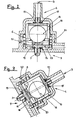
- - Figur 1 ein schematischer Schnitt in Seitenansicht einer Vorrichtung nach einem Ausführungsbeispiel der Erfindung ist;
- - Figur 2 ist eine schematische Schnittansicht einer Absperrvorrichtung nach einer Variante der Erfindung für ein aufrecht stehendes Fahrzeug, und
- - Figur 3 ist analog zu Figur 2 eine Darstellung für ein Fahrzeug in geneigter Stellung.
- Die in Figur 1 dargestellte Vorrichtung ist über einen Ansatz 2 an einem Einfüllstutzen 1 eines Kraftstoffbehälters (nicht dargestellt) angebracht. Ein Sutzen 3, mit dem Behälter verbunden, ist an ein Ventil 4 mit Schließstößel 5 angeschlossen, der durch eine Feder 6 in Öffnungsstellung gehalten wird. Der Ausgang des Ventils 4 steht über einen Kanal 7 mit der freien Luft in Verbindung, der z.B. in den Ansatz 2 mündet. Eine Klappe 8 durch eine Feder 10 auf einem Sitz 9 gehalten, sperrt normalerweise den Durchgang zwischen dem Ansatz 2 und dem Stutzen 1 dichtend ab. Die Klappe 8 wird durch die Zapfpistole (nicht dargestellt) bei deren Einführung in den Stutzen 1 über den Ansatz 2 zurückgeschoben und ermöglicht das Füllen des Behälters.
- Eine Klappe 11, an der Drehachse 12 der Klappe 8 befestigt, wird davon durch einen Schenkel 13 der Feder 10 bis zu einer Anschlagstellung (in der Zeichnung dargestellt) entfernt, in der die Klappe 11 vom Stößel 5 entfernt ist. Im Verlauf der Drehung der Klappe 8 infolge Einschiebens der Zapfpistole drückt die Klappe 8 gegen den Stößel 5 und bewirkt das Schließen des Ventils 4, so daß der Behälter nicht mehr mit der freien Luft in Verbindung steht. Am Ende des Einschubs der Zapfpistole wird die Klappe durch den Schenkel 13 der Feder 10 gegen die Wand des Stutzens 1 gepreßt, nachdem sich die Klappe 11 in bezug auf die Klappe 8 gedreht hat.
- Die Absperrung der Verbindung des Behälters mit der freien Luft während des Füllvorgangs ermöglicht es, im oberen Teil des Behälters, in den der Stutzen 3 mündet, eine Lufttasche zu halten, die verhindert, daß der Kraftstoff in diesem Stutzen aufsteigen kann und bei einem im Behälter herrschenden Überdruck, beim Parken auf einer schiefen Ebene oder in einer Kurve oder aber durch andere Ursachen nach draußen geworfen wird.
- Es wird jetzt auf Figuren 2 und 3 Bezug genommen.
- In normaler Arbeitsstellung nach Figur 2, d.h. während der Behälter nicht gefüllt wird, drückt die Feder 6 die Dichtung 14, fest mit dem Klappengehäuse 15 verbunden, aus dem der Stößel 5 herausragt, gegen ihren Sitz, wodurch die Dichtheit des Einfüllstutzens 1 gewährleistet wird.
- Ein Käfig .16, der eine Dichtung 17 trägt, ist frei beweglich am Klappengehäuse 15 angebracht und enthält eine Kugel 18. In Ruhestellung ruht die Kugel 18 auf dem Boden 19 des Käfigs 16 und wird seitlich durch je eine mit dem Gehäuse 15 fest verbundene schiefe Ebene gehalten.
- Das Gewicht der Kugel 18 stützt den Käfig 16 gegen das Klappengehäuse 15, und die Dichtung 17 wird aus ihrem Sitz am Eintritt des Stutzens 3 abgehoben (Fig. 1).
- Bei einem Kippen des Fahrzeugs (Fig. 3) rollt die Kugel 18 auf einer der schiefen Ebenen und hebt dabei den Käfig 16 vom Klappengehäuse 15 so ab, daß die Dichtung 17 gegen ihren Sitz 21 zu liegen kommt und den Belüftungsstutzen 3 absperrt. Die Abdichtung mit dem Einfüllstutzen bleibt durch die Wirkung der Feder auf das Klappengehäuse 15 erhalten.
Claims (5)
Applications Claiming Priority (4)
| Application Number | Priority Date | Filing Date | Title |
|---|---|---|---|
| FR8515743A FR2588918B1 (fr) | 1985-10-23 | 1985-10-23 | Dispositif de ventilation a securite contre le remplissage excessif pour reservoir de carburant |
| FR8515743 | 1985-10-23 | ||
| FR8607176A FR2599085B2 (fr) | 1986-05-21 | 1986-05-21 | Dispositif de ventilation a securite contre le remplissage excessif pour reservoir de carburant |
| FR8607176 | 1986-05-21 |
Publications (2)
| Publication Number | Publication Date |
|---|---|
| EP0223051A1 EP0223051A1 (de) | 1987-05-27 |
| EP0223051B1 true EP0223051B1 (de) | 1989-06-28 |
Family
ID=26224778
Family Applications (1)
| Application Number | Title | Priority Date | Filing Date |
|---|---|---|---|
| EP19860114072 Expired EP0223051B1 (de) | 1985-10-23 | 1986-10-10 | Sicherheitsbelüftung gegen Überfüllung für Kraftstoff-Behälter |
Country Status (3)
| Country | Link |
|---|---|
| EP (1) | EP0223051B1 (de) |
| DE (1) | DE3664120D1 (de) |
| ES (1) | ES2009759B3 (de) |
Families Citing this family (11)
| Publication number | Priority date | Publication date | Assignee | Title |
|---|---|---|---|---|
| DE3721049C2 (de) * | 1987-06-25 | 1999-01-21 | Temtec Fahrzeugtechnik Entwicklungsgesellschaft Mbh | Selbstschließender Kraftstoffbehälterverschluß |
| EP0296618B1 (de) * | 1987-06-25 | 1990-12-05 | Temtec Fahrzeugtechnik Entwicklungsgesellschaft mbH | Selbstschliessender Kraftstoffbehälterverschluss |
| DE3742259C1 (de) * | 1987-12-12 | 1989-03-02 | Daimler Benz Ag | Kraftstoffbehaelter |
| FR2630686B1 (fr) * | 1988-04-27 | 1991-07-12 | Peugeot | Dispositif de limitation de remplissage d'un reservoir de carburant et vehicule automobile equipe d'un tel dispositif |
| GB2239006B (en) * | 1989-12-12 | 1993-10-06 | Ford Motor Co | A fuel filler arrangement |
| DE4021218A1 (de) * | 1990-07-04 | 1992-01-09 | Blau Kg Kraftfahrzeugtech | Tankfuellstutzen fuer einen treibstofftank |
| FR2668986A1 (fr) * | 1990-11-14 | 1992-05-15 | Transformat Mat Plastiques | Dispositif de securite pour circuit d'alimentation en carburant du reservoir d'un vehicule automobile. |
| FR2668987B1 (fr) * | 1990-11-14 | 1995-07-07 | Transformat Mat Plastiques | Dispositif de securite pour circuit d'alimentation en carburant du reservoir d'un vehicule automobile. |
| FR2668988B1 (fr) * | 1990-11-14 | 1993-02-12 | Transformat Mat Plastiques | Dispositif de securite pour circuit d'alimentation en carburant du reservoir d'un vehicule automobile. |
| FR2762807B1 (fr) * | 1997-04-30 | 1999-06-25 | Coutier Moulage Gen Ind | Embout de fermeture pour tubulure de remplissage d'un reservoir de carburant d'un vehicule automobile |
| WO1999003697A1 (en) * | 1997-07-17 | 1999-01-28 | Tesma International Inc. | Capless refueling assembly |
Family Cites Families (6)
| Publication number | Priority date | Publication date | Assignee | Title |
|---|---|---|---|---|
| AT313082B (de) * | 1971-06-24 | 1974-01-25 | Josef Schwarzboeck | Kraftstoff- bzw. Bezintank |
| SE402076B (sv) * | 1975-02-21 | 1978-06-19 | Saab Scania Ab | Ventilmekanism vid pafyllningsror till vetskebehallare |
| US3996951A (en) * | 1975-11-17 | 1976-12-14 | Parr Manufacturing Inc. | Safety roll over valve |
| FR2372712A1 (fr) * | 1976-12-06 | 1978-06-30 | Renault | Dispositif de securite pour l'aeration d'un reservoir de carburant |
| DE3205782A1 (de) * | 1982-02-18 | 1983-08-25 | Volkswagenwerk Ag, 3180 Wolfsburg | Tankanordnung, insbesondere kraftstoff-tankanordnung fuer ein kraftfahrzeug |
| FR2581597B1 (fr) * | 1985-05-07 | 1990-03-09 | Renault | Dispositif de limitation de remplissage d'un reservoir a carburant, notamment pour vehicule automobile |
-
1986
- 1986-10-10 ES ES86114072T patent/ES2009759B3/es not_active Expired
- 1986-10-10 EP EP19860114072 patent/EP0223051B1/de not_active Expired
- 1986-10-10 DE DE8686114072T patent/DE3664120D1/de not_active Expired
Also Published As
| Publication number | Publication date |
|---|---|
| ES2009759B3 (es) | 1989-10-16 |
| EP0223051A1 (de) | 1987-05-27 |
| DE3664120D1 (en) | 1989-08-03 |
Similar Documents
| Publication | Publication Date | Title |
|---|---|---|
| DE4012368C2 (de) | ||
| DE3742256C1 (de) | Vorrichtung zum Auffangen von Kraftstoffdaempfen beim Betanken eines Kraftstoffbehaelters | |
| DE19747986C2 (de) | Verschluß für einen Tank | |
| EP0223051B1 (de) | Sicherheitsbelüftung gegen Überfüllung für Kraftstoff-Behälter | |
| DE4233038C1 (de) | Überdrucksicherung für einen Kühlmittelkreislauf | |
| EP0089064A1 (de) | Umfüllvorrichtung zum Umfüllen von Flüssigkeiten, insbesondere flüssigem Dauerwellmittel | |
| EP0401459A1 (de) | Verschluss für den Füllstutzen von Flüssigkeitsbehältern | |
| DE69304658T2 (de) | Das Nachfüllen verhinderndes Ventil für nicht nachfüllbare Behälter | |
| DE3527773A1 (de) | Vorrichtung zum betanken von kraftstoffbehaeltern von kraftfahrzeugen, insbesondere motorraedern | |
| DE2143358A1 (de) | Abschaltventil fur eine Flussigkeits abgabeduse | |
| DE2362928B2 (de) | Vorrichtung zum Füllen eines Behälters | |
| DE1158852B (de) | Nachfuellvorrichtung fuer ein hydraulisches UEbertragungssystem, insbesondere fuer Kraftfahrzeugbremsanlagen | |
| DE19936161C1 (de) | Sicherheitsventil insbesondere für eine Betankungsentlüftungsleitung | |
| DE19540267B4 (de) | Tankentlüftung | |
| DE1750241A1 (de) | Drucknachfuellventil | |
| DE69620103T2 (de) | Verbesserte Tankentlüftungsvorrichtung für Kraftfahrzeugtank und Kraftfahrzeugtank mit dieser Vorrichtung | |
| DE10060999C1 (de) | Aufbewahrungsbehälter für Nahrungsmittel mit einem Behälterdeckel | |
| EP0054717B1 (de) | Vorrichtung zur Entnahme von Gas | |
| WO1997008068A1 (de) | Einrichtung zur belüftung eines flüssigkeitsbehälters | |
| DE19812384A1 (de) | Kraftstoffbehälterverschluß | |
| DE1187944B (de) | Zapfvorrichtung fuer fluessige Kraftstoffe | |
| EP0011247B1 (de) | Vorrichtung zur Entlüftung von Kraftstoffbehältern bei Kraftfahrzeugen | |
| DE3916574A1 (de) | Brennstoffbehaelter mit luftblase | |
| EP0282883B1 (de) | Entlüftungsventil zum Entlüften von Kraftstoffbehältern | |
| DE2941173C2 (de) | Sicherheitsventil |
Legal Events
| Date | Code | Title | Description |
|---|---|---|---|
| PUAI | Public reference made under article 153(3) epc to a published international application that has entered the european phase |
Free format text: ORIGINAL CODE: 0009012 |
|
| AK | Designated contracting states |
Kind code of ref document: A1 Designated state(s): DE ES FR GB IT |
|
| 17P | Request for examination filed |
Effective date: 19870418 |
|
| 17Q | First examination report despatched |
Effective date: 19880129 |
|
| GRAA | (expected) grant |
Free format text: ORIGINAL CODE: 0009210 |
|
| AK | Designated contracting states |
Kind code of ref document: B1 Designated state(s): DE ES FR GB IT |
|
| GBT | Gb: translation of ep patent filed (gb section 77(6)(a)/1977) | ||
| REF | Corresponds to: |
Ref document number: 3664120 Country of ref document: DE Date of ref document: 19890803 |
|
| ET | Fr: translation filed | ||
| ITF | It: translation for a ep patent filed | ||
| PGFP | Annual fee paid to national office [announced via postgrant information from national office to epo] |
Ref country code: DE Payment date: 19891129 Year of fee payment: 4 |
|
| PG25 | Lapsed in a contracting state [announced via postgrant information from national office to epo] |
Ref country code: GB Effective date: 19901010 |
|
| GBPC | Gb: european patent ceased through non-payment of renewal fee | ||
| PG25 | Lapsed in a contracting state [announced via postgrant information from national office to epo] |
Ref country code: DE Effective date: 19910702 |
|
| PLBE | No opposition filed within time limit |
Free format text: ORIGINAL CODE: 0009261 |
|
| STAA | Information on the status of an ep patent application or granted ep patent |
Free format text: STATUS: NO OPPOSITION FILED WITHIN TIME LIMIT |
|
| 26N | No opposition filed | ||
| PG25 | Lapsed in a contracting state [announced via postgrant information from national office to epo] |
Ref country code: IT Free format text: LAPSE BECAUSE OF NON-PAYMENT OF DUE FEES;WARNING: LAPSES OF ITALIAN PATENTS WITH EFFECTIVE DATE BEFORE 2007 MAY HAVE OCCURRED AT ANY TIME BEFORE 2007. THE CORRECT EFFECTIVE DATE MAY BE DIFFERENT FROM THE ONE RECORDED. Effective date: 20051010 |
|
| PGFP | Annual fee paid to national office [announced via postgrant information from national office to epo] |
Ref country code: FR Payment date: 20051017 Year of fee payment: 20 |
|
| PGFP | Annual fee paid to national office [announced via postgrant information from national office to epo] |
Ref country code: ES Payment date: 20051026 Year of fee payment: 20 |
|
| PG25 | Lapsed in a contracting state [announced via postgrant information from national office to epo] |
Ref country code: ES Free format text: LAPSE BECAUSE OF EXPIRATION OF PROTECTION Effective date: 20061011 |
|
| REG | Reference to a national code |
Ref country code: ES Ref legal event code: FD2A Effective date: 20061011 |